Contemporary Economic Issues Facing the Filipino Entrepreneur (1).pptx
eTech 6 - Rapid power for the modern electronics system
1. In our previous eTECh article we discussed how the high level power
architecture in complex multi-rail power systems can have a strong influence
on product energy use. This article builds on the initial discussion to describe
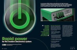
a new concept in power system design - the Rapid Power System (RPS).
figure 1 – Rapid Power System (RPS) Test Unit
“ ...provides New Concept - Rapid Power System The RPS provides a main 12Vdc rail and
Often, provision of the power supply for four user pluggable module zones giving
detailed a new product is considered late in the
development process. The RPS allows a
the capability of up to five DC output rails.
A total system load of 60W is possible
real-time designer to implement a custom multi-rail
power supply at the very first stages of
with module output of up to +/-25Vdc and
+/-6Adc. The test system will monitor the
knowledge new product development which brings minimum, maximum and average value
required to
a number of key benefits: of each DC output voltage and current as
well as measuring mains AC input power,
minimise power 1. The ability for a designer to rapidly
configure a complex multi-rail power
frequency, RMS voltage, RMS current,
system output power, total power loss,
consumption subsystem with minimal power
design experience.
overall conversion efficiency and operating
temperature. Use of the host application
throughout the running on a computer allows the user
”
2. The capability to easily provide detailed to chart all the system variables over
new product power use information during product time in order to provide complete power
Rapid power
development which helps the user to qualification of a new product.
minimise product energy use and form
an accurate power system load profile.
3. The flexibility to modify the power supply
very quickly if the specification changes.
for the modern electronics system
4. A low risk route to easily map the
custom power subsystem into
volume production.
RPS consists of two main products;
by Dr. Iain mosely, Technical Director of Zonetech a prototyping test system which is
www.zonetech.com used during the product development
phase and a generic platform onto which
proven designs can then be mapped for
volume production. Continued page 38>
36 eTech - ISSUE 6 eTech - ISSUE 6 37
2. < Continued from page 37
Example System – External hard Disk Drive measurements
An external hard disk drive requiring +5V and +12V voltage
W mains aC - Power
rails was powered using the RPS system. The data captured 40
shown in Figure 2 details four of the twenty three possible 30
useful measurements during the course of the test:- 20
10
1. PLOT 1 - Shows the power drawn from the 230Vrms mains 0
0 50 100 150 200 250 seconds 300
supply (Note the peak level measured at the start of the test)
V main 12V - Voltage
12.8
12.6
2. PLOT 2 - Shows the voltage measured on the +12V output 12.4
including minimum, maximum and average levels 12.2
12.0
11.8
3. PLOT 3 – Shows the power drawn from the +12V. Again, 11.6
0 50 100 150 200 250 seconds 300
note the peak power consumption at the start of the test
W main 12V - Power
30
4. PLOT 4 – Shows the power drawn from the Z1 Module 25
20
(5VDC in this case). 15
10
5
The results of the hard disk test show that the typical total mains 0
0 50 100 150 200 250 seconds 300
power draw of the product is around 10W in steady state with a
five second peak of about 32W during start-up. Analysis of the W Z1 - Power
4.5
output rail powers show the high peak occurs on the 12V rail and 4.0
3.5
it is most likely that this is the rail used to drive the motors in the 3.0
2.5
hard disk. The 5V rail power is constant until a data read or write 2.0
1.5
1.5 Gb Data Write
Omron
is performed. During a data read/write, the load on the 5V rail 1.0
seconds
0 50 100 150 200 250 300
increases from around 2W to 3.5W, probably a result of moving
the hard disk heads across the disk. Thus, the power supply used to figure 2. Data Captured During Test of an External
drive this disk would have a basic specification of:- Computer hard Disk
tactile switches
+12V/500ma with a 2.3a/5 second peak capability measurements
+5V/800ma W mains aC - Power
30
So, how can we use the data to save energy? 20
The data shows that the power use when the disk is reading or 10
writing data is around 9.6W. The power use when in idle mode is 0
for every day use!
5 10 15 20 25 seconds
7W. In particular, during idle mode, more than 70% of the power
main 12V - Voltage
draw is on the 12V rail and is being used to spin the disks. Since 12.8
V
external hard disk drives are often used for data back-up, the most 12.6
12.4
straightforward way to reduce energy consumption would be to 12.2
12.0
power down the motor during periods of disk inactivity. 11.8
11.6
5 10 15 20 25 seconds
Conclusion
Measurement of product energy use is often only performed at the 30
W main 12V - Power Omron’s range of Tactile Switches is used in many day-to-day
end of the development cycle when the options for improvement 25
20
applications from clock alarms and electric toothbrushes through key
are limited. The use of the RPS system by product designers during
fobs and mp3 players to white goods and so much more.
15
the first stages of the development cycle provide the detailed 10
5
real-time knowledge required to minimise power consumption 0
seconds
throughout the new product.
5 10 15 20 25
Tactile switches are in 6x6mm and 12x12mm configurations in both through-hole
Z1 - Power
4.5
W
and surface-mount versions and all have positive click action and variations that
The simple approach used by RPS provides a low risk solution to 4.0
the complex power requirements of modern products. The speed
3.5
3.0 include horizontal, vertical, flat and projected types. Omron even has the industry’s
2.5
of implementation frees up design engineers to focus on the key 2.0
1.5
smallest positive click action tactile switch.
aspects of their new product design, safe in the knowledge that the
Designed into all Omron switches are quality, operability and user-friendliness.
1.0
5 10 15 20 25 seconds
power system sitting behind it is proven and can be mapped into a
volume product when they move into production. figure 3. This plot shows a zoom of the first 30 seconds Switch to Omron – for more information visit www.omron-rs.eu
find out more about ZoneTech at www.zonetech.com
Get more online...
Share your comments on this article at www.designspark.com
www.omron-rs.eu
38 eTech - ISSUE 6