eTech 6 - Networker - an advanced web server with a micro
1. DESIGN DESIGN
TIPS TIPS
IN aSSOCIaTION WITh
+3V3
GPIO0
GPIO1
GPIO2
MCLR
LEDA
VB1
VA1
VA2
RX
VCC
VA1
GND
TX
VCC
NETWORKER a micro
1 2 3 4 5 6 7 8 9 10
R102 R105
C101 C102 C103 C104 C105 C106 JP2
560R
4k7
100n 100n 100n 100n 100n 100n
+2V5 +3V3
an advanced web server with
19 26 38 48 49 54 57
R103 FE101
AVDD
VDD
VDD
VDDRX
VDDTX
VDDPLL
VDD
MCLR 7 53
1k MCLR RBIAS
18
ENVREG
2 10 R104
RE0/P2D VDDCORE/VCAP 1k @ 100MHz
EEPROM 1 C112
RE1/P2C
2k26
by Sven Schlender (Germany) C107
64
63
RE2/P2B
IC1
RD0/P1B
60
59 GPIO3 10u
TR1
*
100n
62
RE3/P3C
RE4/P3B
RD1/ECCP3/P3A
RD2/CCP4/P3D
58
1 16
61 2 15
RE5/P1C
51 J1
TPOUT+ 3 14 1
8 50
an Internet connection would be a valuable addition RG4/CCP5/P1D TPOUT-
TPIN+
47
6 11
2
3
to many projects, but often designers are put off by
17 46
RF1/AN6/C2OUT TPIN- 4
16 7 10
RF2/AN7/C1OUT 5
the complexities involved. The ‘NetWorker’, which 15
14
RF3/AN8
RF4/AN9
RA0/LEDA/AN0
RA1/LEDB/AN1
24
23
LEDA
LEDB
8 9 6
consists of a small printed circuit board, a free software
7
+3V3 13
RF4/AN10/CVREF RA2/AN2/VREF-
22 GPIO4 R107 R108 R109 R110
ETHER_TRANS_N5 8
12 21 GPIO5
49R9
49R9
49R9
49R9
library and a ready-to-use microcontroller-based web
RF6/AN11 RA3/AN3/VREF+
SPI_CS 11 28
RF7/SS1 RA4/T0CKL
PIC18F6XJ6X 27
server, solves these problems and allows beginners GPIO0 3
RB0/INT0/FLT0
RA5/AN4
C108 C109
to add Internet connectivity to their projects. more
GPIO1 4 30
RB1/INT1 RC0/T1OSO/T13CKI
100n 100n +3V3
GPIO2 5 29
RB2/INT2 RC1/T1OSI/ECCP2/P2A
experienced users will benefit from features such as SPI * VCC
6
44
RB3/INT3
RB4/KBIO
RC2/ECCP1/P1A
RC3/SCK1/SCL1
33 SPI_INT
34 SPI_CLK
IC2 2
communications, power over Ethernet (PoE) and more. MCLR
PGC
MCLR
43
42
RB5/KBI1
RB6/KBI2/PGC
RC4/SDI1/SDA1
RC5/SDO1
35 SPI_MISO
36 SPI_MOSI
VCC
EEPROM
37 31 TX EEPROM 1
PGD RB7/KBI3/PGD RC6/TX1/CK1 SCIO
32 RX
GND 11AA02E48
VSSPLL
RC7/RX1/DT1
VSSRX
VSSTX
AVSS
VSS
VSS
VSS
VSS
There
OSC1 OSC2 GND
are three key elements in voltage (3.3 V is recommended) using the ISP 9 20 45 52 39 40 55 25 41 56 3
R101
connecting a device to an voltage regulator included in the PIC. Pin 1M R106
Ethernet network: the Ethernet connection ENVREG determines whether the voltage Q101
560R
hardware itself, the software library and finally regulator is enabled. A 10 µF capacitor (C112) JP1
C110 C111
the top-level firmware functions. provides smoothing and capacitors C101 to 1 2 3 4 5 6 7 8 9 10
C106 positioned around the microcontroller 33p 25MHz 33p
SPI_MISO
SPI_MOSI
SPI_CLK
SPI_INT
SPI_CS
GPIO4
GPIO5
GPIO3
LEDB
The circuit is based around a Microchip PIC18- decouple the supplies. A 25 MHz crystal
VB1
GND
VB2
VA2
VB2
family microcontroller which includes a built-in (Q101) provides an external clock for the 100552 - 11
Ethernet transceiver. The author has added microcontroller, and the Ethernet transceiver
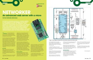
a few new functions to the free C software clock is also derived from this source. figure 1. Circuit diagram showing the PIC microcontroller, transformer and network socket.
library available from the manufacturer that
implements the TCP/IP stack. The final element The project includes a bootloader which A PoE-standard device must support reference current (hence its bizarre value). This Pins VA1, VA2, VB1 and VB2 allow the module
of the project is a web server running on the allows new firmware to be uploaded over the both possibilities. To take advantage of the in turn determines the signal amplitude on to be used in conjunction with a power over
microcontroller which can communicate with Ethernet interface. The reset circuit comprises phantom supply a special transformer is TPOUT+ and TPOUT–. Ethernet regulator, sometimes called a ‘PD
other hardware via the I/O pins of the device. R102, R103 and C107 R102 is a pull-up resistor,
. circuit from the network. On the far side of the needed with centre taps to the windings on module’.
Other advanced features can be implemented and R103 and C107 filter the reset signal to transformer is an RJ45 socket J1, into which a the network side. There are two LEDs mounted inside the
such as PoE. Now let’s see what makes the prevent spurious resets. C107 can interfere standard Ethernet cable can be plugged. Ethernet socket. LED1 lights when the link is The active-low MCLR pin allows the module
module tick. with the operation of the ICSP interface, and so A special feature of the transformer we have A suitable PoE regulator circuit can be up and LED2 indicates network activity. The to be reset. It is also pulled low briefly when
should be removed if it is to be used. chosen is its compatibility with the IEEE connected to these headers to derive a supply LEDs are driven from the PIC via series current- power is applied to the module.
The circuit The EEPROM stores configuration data. It 802.3af power over Ethernet (PoE) standard. for the module from the 48 V DC provided over limiting resistors R105 and R106.
Figure 1 shows the circuit of the module. also includes a 48-bit ID code, called the MAC Under this standard a 48 V supply is provided the network.
At the heart of the unit is a Microchip address, required for Ethernet communication. on the network and a powered device (PD) can User-side interface
PIC18F67J60. Most of the circuitry required draw current from this supply. There are two Resistors R107 to R110 provide impedance The user-side interface consists of two 10-way Continued page 30 >
is provided in the device and only a few Ethernet interface alternative arrangements possible. matching, and C108, C109 and FE101 help 0.1 inch pitch headers. As well as carrying
external components are needed to connect The connection to the Ethernet network reduce the effect of interference spikes on the PoE connections and the module’s power
to a network. comprises four signals, TPOUT+, TPOUT–, 1. using the spare conductor pairs (on J1 these the network connections. supply, the headers are also directly connected
TPIN+ and TPIN–. These signals are passed are pins 4 and 5 and pins 7 and 8); or to certain pins on the microcontroller.
The Ethernet PICs require a 2.5 V core voltage via the Ethernet transformer TR1, which 2. phantom supply over the signal pairs (pins 1 R104 is a bias resistor that provides the The supply voltage should be between
supply, which can be derived from a higher galvanically isolates the main part of the and 2 and pins 3 and 6). Ethernet transceiver circuit with a known 3.1 V and 3.6 V.
28 eTech - ISSUE 6 eTech - ISSUE 6 29
2. DESIGN knitter-switch Multi-Function
TIPS number one in switches Tact Switches
Switches for all Applications
< Continued from page 29 5 Million Switches in Stock
Worldwide Support rswww.com/knitter-switch
Communications be extended and modified as long as it is Using the module
Pins TX and RX are connected to a UART that only used in Microchip devices. It contains a A simple way to find out what IP address has
can support speeds of up to 115200 baud. rich collection of hardware drivers, low-level been acquired is to use Bonjour, a program
An SPI interface is available on the pins with protocol implementations (ARP IP TCP and so
, , developed by Apple which is now also available Toggle Switches Tact Switches
labels starting ‘SPI’. The interface can operate on) and a couple of important application-level for Windows (most simply installed as a
in master mode or in slave. protocol implementations such as DHCP and
HTTP The simple MPFS file system is also
.
browser plug-in, for example for Firefox [2]).
Rotary Coded Dual-in-line
Software library
A ‘stack’ is a collection of software
included to allow storage of web page source
data. Example applications, a bootloader, tools
Serial modes
When a suitable network connection is
Switches Switches
Slide Switches Micro Switches
implementations of protocols and drivers, and comprehensive documentation of all stack established with the serial server data can
usually arranged in a hierarchy of layers. At functions complete the package. be sent using TCP/IP to the unit. Further
the bottom end of the stack are the hardware details on the additional protocols required
drivers which are responsible for getting data application software for operation in this mode can be found in a
bits transferred onto the network wires. At the The module has an integrated bootloader that supplementary document downloadable knitter-switch
top end of the stack is a simple interface for
data exchange.
allows a new version of its firmware to be
uploaded over the Ethernet connection for
from the Elektor website.
Pushbutton knitter-switch UK Limited
Switches
Grove House, Lutyens Close,
installation at any time: suitable hex files are
Chineham Court, Basingstoke,
In theory, the layered protocol model makes available on the project’s web pages [1]. The
RG24 8AG, United Kingdom
it relatively easy to make modifications to one author developed the application software
layer (such as the hardware driver) without for the module using the MPLAB IDE. It is Rotary Switches Tel: +44 (0) 1256 338670
affecting the others. In practice however, written entirely in ANSI C and can be Fax: +44 (0) 1256 338671
Encoders
when implemented on a microcontroller, the compiled using the free version of the Email: ksuk@knitter-switch.com
hardware and the stack are very closely tied Microchip C18 compiler. www.knitter-switch.com
together, and lots of tricks need to be used to
keep memory usage low. Nevertheless, TCP/IP The application consists of three modules,
stack implementations are available for a wide called Main, Web and Appl. The bootloader
range of microcontroller families, often for free jumps directly to Main, where the TCP/IP stack,
and direct from the manufacturer. the EEPROM driver and the Appl module are
Microchip offers a TCP/IP stack for its PIC18, initialised. Then Appl and the TCP/IP stack Internet Links
PIC24, dsPIC and PIC32 microcontroller receive processing time alternately in an [1] www.elektor.com/100552
families written in ANSI C. It is free and can infinite loop. [2] www.bonjourfoxy.net
DesignSparkPCB
Component list
Resistors (SmD 0603) RS Stock No. Semiconductors RS Stock No
R101 = 1MΩ 678-9932 IC1= PIC18F67J60 (TQFP64), 400-766
R102 = 4.7kΩ 679-0484 IC2= 11AA02E48 (SOT23) 667-8034
R103 = 1kΩ 678-9875 TR1= 10/100Base-TX transformer,
NeW 3d vieWer
R104 = 2.26kΩ 679-0128
Halo N5 (SMD), PoE to IEEE 802.3af 615-4406 or 615-4434
R105,R106 = 560Ω 679-0541
R107–R110 = 49.9Ω (1%) 679-0459
miscellaneous RS Stock No.
reLeaSeS your
J1= 8+2+2 pin RJ45 socket, w. 2 integrated LEDs
(use integrated TR1)
Capacitors (SmD 0603): RS Stock No. JP1,JP2 = 10-pin SIL pinheader (lead pitch 0.1 in.) 681-3004
C101–C109= 100nF 391-246 Q101 = 25 MHz SMD quartz crystal, HC49UP case 671-9280
C110,C111= 33pF 616-9161 PCB, Elektor # 100552-11 [1]
CreaTiviTy
C112= 10µF 698-3239 http://be.eurocircuits.com/Offtheshelf/Offtheshelfdefault.aspxw
Inductors (SmD 0603): RS Stock No.
FE101 = 1k @ 100 MHz 367-4856
The World’s Most Powerful Free Schematic and
PCB Layout Tool is yours to download now
Get more online...
www.designspark.com Download your free copy at
www.designspark.com/pcb WIrED BY
30 eTech - ISSUE 6

![DESIGN knitter-switch Multi-Function
TIPS number one in switches Tact Switches
Switches for all Applications
< Continued from page 29 5 Million Switches in Stock
Worldwide Support rswww.com/knitter-switch
Communications be extended and modified as long as it is Using the module
Pins TX and RX are connected to a UART that only used in Microchip devices. It contains a A simple way to find out what IP address has
can support speeds of up to 115200 baud. rich collection of hardware drivers, low-level been acquired is to use Bonjour, a program
An SPI interface is available on the pins with protocol implementations (ARP IP TCP and so
, , developed by Apple which is now also available Toggle Switches Tact Switches
labels starting ‘SPI’. The interface can operate on) and a couple of important application-level for Windows (most simply installed as a
in master mode or in slave. protocol implementations such as DHCP and
HTTP The simple MPFS file system is also
.
browser plug-in, for example for Firefox [2]).
Rotary Coded Dual-in-line
Software library
A ‘stack’ is a collection of software
included to allow storage of web page source
data. Example applications, a bootloader, tools
Serial modes
When a suitable network connection is
Switches Switches
Slide Switches Micro Switches
implementations of protocols and drivers, and comprehensive documentation of all stack established with the serial server data can
usually arranged in a hierarchy of layers. At functions complete the package. be sent using TCP/IP to the unit. Further
the bottom end of the stack are the hardware details on the additional protocols required
drivers which are responsible for getting data application software for operation in this mode can be found in a
bits transferred onto the network wires. At the The module has an integrated bootloader that supplementary document downloadable knitter-switch
top end of the stack is a simple interface for
data exchange.
allows a new version of its firmware to be
uploaded over the Ethernet connection for
from the Elektor website.
Pushbutton knitter-switch UK Limited
Switches
Grove House, Lutyens Close,
installation at any time: suitable hex files are
Chineham Court, Basingstoke,
In theory, the layered protocol model makes available on the project’s web pages [1]. The
RG24 8AG, United Kingdom
it relatively easy to make modifications to one author developed the application software
layer (such as the hardware driver) without for the module using the MPLAB IDE. It is Rotary Switches Tel: +44 (0) 1256 338670
affecting the others. In practice however, written entirely in ANSI C and can be Fax: +44 (0) 1256 338671
Encoders
when implemented on a microcontroller, the compiled using the free version of the Email: ksuk@knitter-switch.com
hardware and the stack are very closely tied Microchip C18 compiler. www.knitter-switch.com
together, and lots of tricks need to be used to
keep memory usage low. Nevertheless, TCP/IP The application consists of three modules,
stack implementations are available for a wide called Main, Web and Appl. The bootloader
range of microcontroller families, often for free jumps directly to Main, where the TCP/IP stack,
and direct from the manufacturer. the EEPROM driver and the Appl module are
Microchip offers a TCP/IP stack for its PIC18, initialised. Then Appl and the TCP/IP stack Internet Links
PIC24, dsPIC and PIC32 microcontroller receive processing time alternately in an [1] www.elektor.com/100552
families written in ANSI C. It is free and can infinite loop. [2] www.bonjourfoxy.net
DesignSparkPCB
Component list
Resistors (SmD 0603) RS Stock No. Semiconductors RS Stock No
R101 = 1MΩ 678-9932 IC1= PIC18F67J60 (TQFP64), 400-766
R102 = 4.7kΩ 679-0484 IC2= 11AA02E48 (SOT23) 667-8034
R103 = 1kΩ 678-9875 TR1= 10/100Base-TX transformer,
NeW 3d vieWer
R104 = 2.26kΩ 679-0128
Halo N5 (SMD), PoE to IEEE 802.3af 615-4406 or 615-4434
R105,R106 = 560Ω 679-0541
R107–R110 = 49.9Ω (1%) 679-0459
miscellaneous RS Stock No.
reLeaSeS your
J1= 8+2+2 pin RJ45 socket, w. 2 integrated LEDs
(use integrated TR1)
Capacitors (SmD 0603): RS Stock No. JP1,JP2 = 10-pin SIL pinheader (lead pitch 0.1 in.) 681-3004
C101–C109= 100nF 391-246 Q101 = 25 MHz SMD quartz crystal, HC49UP case 671-9280
C110,C111= 33pF 616-9161 PCB, Elektor # 100552-11 [1]
CreaTiviTy
C112= 10µF 698-3239 http://be.eurocircuits.com/Offtheshelf/Offtheshelfdefault.aspxw
Inductors (SmD 0603): RS Stock No.
FE101 = 1k @ 100 MHz 367-4856
The World’s Most Powerful Free Schematic and
PCB Layout Tool is yours to download now
Get more online...
www.designspark.com Download your free copy at
www.designspark.com/pcb WIrED BY
30 eTech - ISSUE 6](data:image/gif;base64,R0lGODlhAQABAIAAAAAAAP///yH5BAEAAAAALAAAAAABAAEAAAIBRAA7)