IDEAL AND PRACTICAL TRANSFORMER, EQUIVALENT CIRCUIT OF TRANSFORMER|DAY5|BASIC ELECTRICAL ENGINEERING
•Download as PPTX, PDF•
2 likes•1,018 views

#IDEAL_PRACTICAL_TRANSFORMER #EQUIVALENT_CIRCUIT OF TRANSFORMER #BASIC ELECTRICAL ENGINEERING #IDEAL TRANSFORMER ON NO LOAD #PRACTICAL TRANSFORMER ON LOAD #ELECTRCL TRANSFORMER #SINGLE PHASE TRANSFORMER Link of all sessions are. DAY 1 (Need/Definition) https://youtu.be/BvaykFJ_NoE DAY 2 (Working principle and Construction) https://youtu.be/06rgxocihaM DAY 3 (EMF equation and Turns Ratio) https://youtu.be/g7e5xBPmv3Y DAY 4 (Classification of Transformer) https://youtu.be/6NP5L4MlvY4 DAY 5 ( Ideal and practical transformer on no load) (Equivalent Transformer) https://youtu.be/6LCLQC1p3lg

Recommended
More Related Content
What's hot
What's hot (20)
Similar to IDEAL AND PRACTICAL TRANSFORMER, EQUIVALENT CIRCUIT OF TRANSFORMER|DAY5|BASIC ELECTRICAL ENGINEERING
Similar to IDEAL AND PRACTICAL TRANSFORMER, EQUIVALENT CIRCUIT OF TRANSFORMER|DAY5|BASIC ELECTRICAL ENGINEERING (20)
More from Prasant Kumar
More from Prasant Kumar (20)
Recently uploaded
Recently uploaded (20)
IDEAL AND PRACTICAL TRANSFORMER, EQUIVALENT CIRCUIT OF TRANSFORMER|DAY5|BASIC ELECTRICAL ENGINEERING
- 1. Prof.Prasant Tiwari IDEAL & PRACTICAL TRANSFORMER EQUIVALENT CIRCUIT ELECTRICAL TRANSFORMER
- 2. ELECTRICAL TRANSFORMER Transformer Syllabus Definition/Need of transformer Principle of Operation Construction EMF Equation Transformation Ratio Classification of Transformer Comparison between core & shell type Ideal & Practical Transformer Equivalent Circuit Losses in a Transformer Efficiency Day 1 Day 4 Day 3 Day 2
- 3. IDEAL TRANSFORMER Properties of ideal transformer Primary and secondary windings has no resistance. All the flux produced by the primary links the secondary winding i,e., there is no leakage flux. Permeability μr of the core is infinitely large. In other words, to establish flux in the core vanishingly small (or zero) current is required. Core loss comprising of eddy current and hysteresis losses are neglected. Ideal transformer on No load
- 4. PRACTICAL TRANSFORMER ON NO LOAD When the transformer is operating at no load, the secondary winding is open-circuited. Which means there is no load on the secondary side of the transformer and, therefore, current in the secondary will be zero. While primary winding carries a small current I0 called no-load current which is 2 to 10% of the rated current. The no-load current consists of two components: Reactive or magnetizing component Im It is in quadrature with the applied voltage V1. It produces flux in the core and does not consume any power). Active or power component Iw, Also know as a working component.It is in phase with the applied voltage V1. It supplies the iron losses and a small amount of primary copper loss. Iw = working component of I0 Im = Reactive or magnetizing component
- 5. STEPS TO DRAW THE PHASOR DIAGRAM on NO LOAD The following steps are given below to draw the phasor diagram: 1. The function of the magnetizing component is to produce the magnetizing flux, and thus, it will be in phase with the flux. 2. Induced emf in the primary and the secondary winding lags the flux ϕ by 90 degrees. 3. The primary copper loss is neglected, and secondary current losses are zero as I2 = 0. 4. Therefore, the current I0 lags behind the voltage vector V1 by an angle ϕ0 called the no-load power factor angle and is shown in the phasor diagram above. 5. The applied voltage V1 is drawn equal and opposite to the induced emf E1 because the difference between the two, at no load, is negligible. 6. Active component Iw is drawn in phase with the applied voltage V1. 7. The phasor sum of magnetizing current Im and the working current Iw gives the no-load current I0.
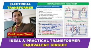
- 6. EQUIVALENT CIRCUIT OF TRANSFORMER It makes the analysis of transformer very easy at any load condition. The iron losses can be obtained. The copper losses at any load can be obtained. Per unit parameter can be obtained. Efficiency regulation and power factor at any load can be obtained without actual loading Need of Equivalent circuit of transformer
- 7. EQUIVALENT CIRCUIT OF TRANSFORMER Case 1 - Secondary referred to primary Case 2 – Primary referred to Secondary
- 8. APPROXIMATE EQUIVALENT DIAGRAM OF TRANSFORMER Case 1 – Secondary referred to primary Case 2 – Primary referred to Secondary
- 9. ELECTRICAL TRANSFORMER Transformer Syllabus Definition/Need of transformer Principle of Operation Construction EMF Equation Transformation Ratio Classification of Transformer Comparison between core & shell type Ideal & Practical Transformer Equivalent Circuit Losses in a Transformer Efficiency Day 1 Day 4 Day 3 Day 2 Day 5