Nonlinear Phenomena in a Free-Running Current Controlled ́Cuk Converter
•
0 likes•43 views


Recommended
Recommended
More Related Content
What's hot
What's hot (19)
Viewers also liked
Viewers also liked (14)
Similar to Nonlinear Phenomena in a Free-Running Current Controlled ́Cuk Converter
Similar to Nonlinear Phenomena in a Free-Running Current Controlled ́Cuk Converter (20)
Nonlinear Phenomena in a Free-Running Current Controlled ́Cuk Converter
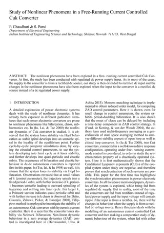
- 1. Study of Nonlinear Phenomena in a Free-Running Current Controlled ´Cuk Converter P. Chaudhuri & S. Parui Department of Electrical Engineering Indian Institute of Engineering Science and Technology, Shibpur, Howrah 711103, West Bengal ABSTRACT: The nonlinear phenomena have been explored in a free- running current controlled ´Cuk Con- verter. At first, the study has been conducted with regulated dc power supply input. As in most of the cases, the supply to the converter is from a rectified dc source, our study is then extended to rectified dc input and the changes in the nonlinear phenomena have also been explored when the input to the converter is a rectified dc source instead of a dc regulated power supply. 1 INTRODUCTION A detailed exploration of power electronic systems deals with the study of nonlinear dynamics. It has already been explored in different published litera- tures that such power electronic converters are prone to nonlinear phenomena like bifurcation, chaos, sub- harmonics etc. In (Iu, Lai, & Tse 2000) the nonlin- ear dynamics of ´Cuk converter is studied. It is ob- served that the system loses stability via Hopf bifur- cation as stable spiral develops into an unstable spi- ral in the locality of the equilibrium point. Further cycle-by-cycle computer simulations done, by vary- ing the circuital control parameters, to see the sys- tem developing into limit cycle as it loses stability, and further develops into quasi-periodic and chaotic orbits. The occurrence of bifurcation and chaotic be- haviour in dc-dc autonomous converters is reported first in this paper. In (Tse, lai, & Iu 1998) as well, it is shown that the system loses its stability via Hopf bi- furcation. Observations revealed that at small values of k (control parameter), the trajectory spirals into a fixed period-1 orbit, with further increase of k, period- 1 becomes unstable leading to outward spiralling of trajectory and settling into limit cycle. For larger k, a Poincar´e section indicates quasi periodic orbit and with further increase in k chaos is observed. In (Daho, Giaonris, Zahawi, Picker, & Banerjee 2008), Filip- povs method is employed to investigate the stability of an autonomous ´Cuk converter with hysteresis current controller. Here it is seen that the converter loses sta- bility via Neimark Bifurcation. Non-linear dynamic behaviour in a zero average dynamics (ZAD) con- trol is investigated here in (Deivasundari, Uma, & Ashita 2013). Moment matching technique is imple- mented to obtain reduced order model, for computing ZAD control parameters. Here it is shown, even for small change in control parameters, the system ex- hibits period-doubling bifurcation. It is also shown that the onset of chaos can be delayed by including a time delay component in ZAD control strategy. In (Fuad, de Koning, & van der Woude 2004), the au- thors have used multi-frequency averaging as a gen- eralisation of state space averaging method to anal- yse different stability aspects of open loop as well as closed loop converter. In (Iu & Tse 2000), two ´Cuk converters, connected in a well-known drive response configuration, operating under free- running current- mode control is considered, in order to study the syn- chronization property of a chaotically operated sys- tem. Here it is first mathematically shown that the Conditional Lyapunov exponents (CLEs) of the cou- pled system under study are negative, and therefore proven that synchronization of such systems are pos- sible. This paper for the first time has highlighted the synchronization phenomenon in power electronic converters. In all the above mentioned papers, dynam- ics of the system is explored, while being fed from regulated dc supply. But in reality, most of the time the converters are fed from rectifiers instead of regu- lated power supply and the input voltage will contain ripple if the input is from a rectifier. So, there will be changes in behaviour when the supply is from a recti- fied dc voltage source. Hence this paper deals with the modelling of an autonomous current controlled ´Cuk converter and then making a comparative study of dy- namic behaviour of the system, when fed with either
- 2. Figure 1: Schematic diagram of ´Cuk converter under Hystereis controller. Figure 2: A sample plot of sum of the inductor currents, i.e, the switch current and the gate pulse of the switch. of the supplies. 2 SYSTEM DESCRIPTION System under study consists of a ´Cuk converter being operated by a free-running hysteretic current mode control (Figure 1). Turning on and off of the switch is done in a hysteretic fashion, based on the values of sum of inductor currents, Isum = (i1 + i2), falling below and above a certain preset hysteretic band (Fig- ure 2) . The governing control equation of the hystere- sis controller is given by (i1 + i2) = g(v1),where, i1 and i2 are the inductor currents respectively, v1 is the output voltage, g(.) is the control function (Tse, lai, & Iu 1998). A simple proportional control takes the form ∆(i1 + i2) = −µ∆v1, µ being the gain factor. The fol- lowing equivalent form of the above equation, assum- ing regulated output is given by, (i1 + i2) = k −µ∆v1, where k and µ are control parameters. 3 SIMULATION RESULTS The modelling of the system done with the follow- ing values of the parameters: E = 30V, L = 0.01H, C = 100µF, R = 25Ω, k = 0.4. Trajectory plotting of the same, using output voltage(v1), voltage across in- put capacitor(v) and inductor current through L1 (iL1) is done for different sets of parameter values. When the input is from a dc regulated power supply, E = Vdc and if the input is from a rectifier, the input voltage will contain a dc component along with a ripple com- ponent of the voltage, E = Vdc + Vm sin(nωt + θ), where Vm is the peak value of the ripple component, n is the order of harmonic present in the output of the rectifier, ω is the angular frequency of the ac supply, θ is the angle between the instant of initial switching of (a) (b) Figure 3: Using regulated dc source, k = 1 (a) trajectory plotting for k = 1,(b) time plot of Isum, iL1, iL2. Figure 4: Trajectory plotting for k = 1 using rectified dc source. the converter and zero crossing of the ripple voltage. For our model, it has been assumed that the input is fed from a single phase diode rectifier with maximum 10% ripple peak of 100Hz. So n = 2, Vm = 0.1Vdc , ω = 314 rad/s, and θ has been taken as zero. Now, analysis of the system behaviour is done using both a regulated dc supply and rectifier input respectively and changes in the nature of the trajectory is marked. 3.1 For k = 1 Keeping all the other controlling and converter pa- rameters fixed and varying value of k, system trajec- tories are plotted. With regulated dc supply, a stable limit cycle is obtained. We see from Figures 3(a),(b) that almost steady dc components of individual iL1 and iL1 obtained. Proper switching is exhibited with Isum remaining within the hysteresis band through- out. The same study is done with a rectified dc sup- ply shows that an additional ripple content of 10% is there in the input voltage. Vdc = 30, Vm = 10% of 30V, i.e. 3V, value chosen for n = 2, i.e. it is assumed that an additional ripple peak of 3V of 100Hz is fed from a single phase diode rectifier input. The trajectory in Figure 4 shows the occurrence of a limit cycle in this case even though having a different structural pattern. Reflection of switching frequency in the structure, be- ing superimposed on the ripple frequency is observed in the structure of limit cycle. From Figure 5(a) we see ripple content of the input is reflected in the output
- 3. (a) (b) (c) Figure 5: Using rectified dc voltage source for k = 1, time plots for (a) Isum, iL1, iL2, (b) Isum, iL1, iL2 using extended scale, (c) iL1. quantities. Second order harmonic, ripple frequency of 100Hz superimposed on the waveform, which is reflected in the output waveforms, of the individual components as well as in the band envelope. The hys- teresis band, formed by the upper and lower limits re- spectively is also remaining bounded within the en- velope consisting of 100Hz frequency. Figure 5(b) is plotted, by enlarging the time shows the switching fre- quency of Isum, along with iL1 and iL2 individually re- spectively. Figure 5(c) is used to show one half cycle (corresponding to 100Hz) of the above waveform. 3.2 For k = 4: We see from Figure 6(a) that a limit cycle is obtained with dc regulated supply, the structure depicting the occurrence of oscillatory current, in repetitive man- ner. Figure 6(b) depicts Isum and the individual induc- tor currents respectively. In (Parui & Basak 2014) it is pointed that due to chosen circuit parameters in a non- autonomous current controlled ´Cuk converter, iL1 and iL2 be oscillatory. In this case, a current component of high frequency (at switching frequency) is super- imposed on a sinusoidal current component of com- paratively lower frequency decided by the circuit L and C values. Figure 7 shows the path (shown in dot- ted lines) traversed by the oscillatory current (Parui & Basak 2014). The frequency of this oscillatory cur- (a) (b) Figure 6: (a) Trajectory plot for k = 4 using regulated voltage source, (b) Time plot of Isum, iL1, iL2 for k = 4 (Regulated dc voltage source). Figure 7: Path of LC Oscillatory current. rent, is given by fosc = 1/(2π Leq.Ceq) (1) where, Leq = L1 + L2 (2) Ceq = C1.C2/(C1 + C2) (3) The above mentioned oscillatory component of cur- rent is termed as LC oscillation current. In (Wong, Wu, & Tse 2008), a slow scale oscillation has been reported in ´Cuk converter, but no quantitative infor- mation and reason for the onset of such oscillation are available regarding the oscillation frequency. As shown in Figure 7, we see that with the chosen values for capacitor and inductor respectively, an LC oscil- latory current is generated over here as well in free running current controlled ´Cuk converter. Isum even- tually leaves the band envelope in a periodic man- ner. Theoretically frequency of LC oscillatory current should be (from (1)) = 160Hz. Frequency obtained from time plot=166.67 Hz. The calculated frequency of the oscillatory current is approximately equal to the frequency as obtained from the time plot of the indi- vidual waveforms. Figure 8 shows the trajectory with
- 4. Figure 8: Trajectory plot for k = 4 using rectified dc voltage source. (a) (b) Figure 9: Using rectified dc voltage source for k = 4 (a) Time plot for Isum, iL1, iL2, (b) Time plot for iL1. rectified dc source as input. Here we see that mul- tiple non-overlapping loops with similar structure is obtained. Because of the existence of the input rip- ple, there is a disruption in the repetitive occurrence of a single structure, giving rise to a complex dynam- ics in the state system. The reason for such complex- ity can be understood from the time plots of inductor currents and switch current, Isum. Figure 9(a) consists of time plot of Isum and the individual currents respec- tively, when a rectified dc voltage source is used, for the value of k = 4. Here we see that Isum fails to re- main within the band for a continuous period of time in a similar manner as found with dc regulated power supply. But, here the input ripple is changing the os- cillation frequency which is not same as obtained with mathematical expression given in (1). Now oscilla- tion frequency is found to be 150Hz which is nei- ther 100Hz, nor 160Hz. Figure 9(b) shows the blow up of the time plot of iL1, for k = 4, using recti- fied dc voltage source. Here we see that the faster switching dynamics of iL1 is aperiodic and it is rid- ing on the LC oscillation of much lower frequency. In a non-autonomous system, there is a fixed switching frequency, so we can refer the occurrence of quasi- periodicity or phase locking due to the interaction of switching frequency and LC oscillation frequency. But here as it is an autonomous system, the switching frequency in not fixed. So we can not define it as a quasi-periodic orbit, but it is giving rise to a complex trajectory in the state space similar to a quasi-periodic attractor in a non-autonomous system. 4 CONCLUSION The nonlinear phenomena have been observed with regulated dc input as well as with rectified dc input. A stable limit cycle is observed for lower values of k with regulated dc input. With the input from a single phase rectifier, there is a 2nd order harmonic compo- nent (because of 100Hz input ripple) in the current waveforms as well as in the band envelope. Oscilla- tory behaviour is observed for values of k above 4. LC oscillation is been generated with dc regulated volt- age supply, compelling the switch current to come out of the hysteresis band. Whereas, when rectified DC voltage source is been used, the input voltage ripple affects the LC oscillation and a third frequency (nei- ther LC oscillation frequency nor 100Hz ripple) is re- flected at the output. REFERENCES Daho, I., D. Giaonris, B. Zahawi, V. Picker, & S. Banerjee (2008). Stability analysis and bifurcation control of hystere- sis current controlled cuk converter using filippov’s method. In 4th IET Conference on Power Electronics, Machines and Drives (PEMD). Deivasundari, P., G. Uma, & S. Ashita (2013). Chaotic dynamics of a zero average dynamics controlled dcdc cuk converter. IET Power Electronics 7(2), 289–298. Fuad, Y., W. L. de Koning, & J. W. van der Woude (2004). On the stability of the pulsewidth-modulated C´uk converter. IEEE Transactions on Circuits & Systems-II 51(8), 412–420. Iu, H. H. C., Y. M. Lai, & C. K. Tse (2000). Hopf bifurcation and chaos in a free-running current-controlled ´Cuk switching regulator. IEEE Transactions on Circuits & Systems–I 47(4), 448–457. Iu, H. H. C. & C. K. Tse (2000). A study of synchronization in chaotic autonomous ´Cuk dc/dc converters. IEEE Transac- tions on Circuits & Systems–I 47(6), 913–918. Parui, S. & B. Basak (2014). Inherent oscillation in C´uk con- verter and its effect on bifurcation phenomena. In IEEE TEN- CON. Tse, C. K., Y. lai, & H. H. C. Iu (1998). Hopf bifurcation and chaos in a hysteretic current-controlled ´Cuk regulator. In IEEE Power Electronics Specialists’ Conference. Wong, S. C., X. Wu, & C. K. Tse (2008). Sustained slow-scale oscillation in higher order current-mode controlled converter. IEEE Transactions on Circuits and Systems-II 55(5), 489– 493.