3. IMPORTANT SAFETY INSTRUCTIONS
READ AND FOLLOW ALL INSTRUCTIONS
DANGER To reduce the risk of injury, do not permit children to use this product unless
they are closely supervised at all times.
WARNING - RISK OF CHILD DROWNING. Extreme caution must be exercised to prevent
unauthorized access by children. To avoid accents, ensure that children cannot use a
spa or hot tub unless they are supervised at all times.
DANGER To reduce the risk of injury to persons, do not remove suction fitting covers.
Spa location must accommodate sufficient drainage of water around the base of the
structure, as well as the power source compartment.
Prolonged immersion in water that is warmer than normal body temperature can result
in a dangerous condition known as HYPERTHERMIA. The causes, symptoms, and
effects of hyperthermia may be described as follows: several degrees above the
normal body temperature of 98.6˚F. The symptoms of hyperthermia include dizziness,
fainting, drowsiness, lethargy, and an increase in the internal temperature of the body.
The effects of hyperthermia include (1) unawareness of impending hazard, (2) failure
to perceive heat, (3) failure to recognize the need to exit spa, (4) physical inability
to exit spa, (5) fetal damage in pregnant women, (6) unconsciousness resulting in
danger of drowning. WARNING The use of alcohol, drugs or medication can greatly
increase the risk of fatal hyperthermia in hot tubs and spas.
DANGER - RISK OF ELECTRICAL SHOCK. Install at least 5 feet (1.5m) from all metal
surfaces. (A spa may be installed within 5 feet of metal surfaces if each metal surface
is permanently connected by a solid copper conductor attached to the ground bar
on the terminal box that is provided for this purpose. Refer to NEC and local codes in
effect at the time of installation.)
A ground or bonding bar is provided on the control box to permit connection of a solid
copper bonding conductor between this point and any equipment, metal enclosures
of electrical equipment, metal water pipe, or conduit within 5 feet (1.5m) of the unit as
needed to comply with local requirements.
Bond accessible metal to the dedicated connector on the equipment grounding bus,
bond the equipment ground bus to the local common bonding grid as part of the
installation in the form of (1) a reinforced concrete slab for support, (2) a ground plate
provided beneath the hot tub or spa, or (3) a permanent ground connection that is
acceptable to the local inspection authority.
DANGER RISK OF ELECTRICAL SHOCK. Do not permit any electrical appliance such as
a light, telephone, radio, or television, within 5 feet (1.5m) of a spa or hot tub.
To reduce the risk of injury:
The water in a spa or hot tub should never exceed 104˚F (40˚C). Water temperatures
between 100˚F (38˚C) and 104˚F (40˚C) are considered safe for a healthy adult.
Lower water temperatures are recommended for extended use (exceeding 10-15
minutes) and for young children.
Excessive water temperatures have a high potential for causing fetal damage during the
early months of pregnancy. Pregnant or possibly pregnant women should limit spa
or hot tub water temperatures to 100˚F (38˚C).
Wholesale 2
http://www.MyPoolSpas.com Pool and Spa Parts 920-925-3094
4. Before entering the spa or hot tub, the user should measure the water temperature with an
accurate thermometer.
The use of alcohol, drugs, or medication before or during spa or hot tub use may lead to
unconsciousness with the possibility of drowning.
Persons suffering from obesity or with a medical history of heart disease, low or high blood
pressure, circulatory system problems, or diabetes should consult a physician before
using a spa or hot tub.
Persons using medication should consult a physician before using a spa or hot tub since
some medication may affect heart rate, blood pressure, and circulation.
For Units with a GFCI (Ground Fault Circuit Interrupter)
This appliance is provided with a ground-fault-circuit-interrupter located on the control box.
Before each use and with the unit operating, push the test button. The unit should
stop operating and the reset button should appear. Push the reset button. The unit
should now operate normally. If the interrupter does not perform in this manner, a
ground current is flowing indicating the possibility of electrical shock. Disconnect the
power, or unplug from receptacle, until the fault has been identified and corrected.
For Cord and Plug Connected Units
Connect to a grounded, grounding type receptacle only. NEVER connect the spa to an
extension cord.
Do not bury the cord.
WARNING To reduce the risk of electrical shock, replace damaged cord immediately.
For Permanently Installed Units
A terminal marked “G” or “ground” is provided in the wiring box located inside the
equipment compartment. To reduce the risk of electric shock, connect the terminal
or connector to the grounding terminal of your electrical service or supply panel with
a continuous green insulated copper wire in accordance with National Electric Code
Table 250-95 and any other local codes in effect at the time of installation.
For Permanently Installed Units not Provided with an Internal
Disconnecting Method
The electrical supply for this product must include a suitably rated switch or circuit breaker
to open all ungrounded supply conductors to comply with Section 422-30 of the
National Electric Code, ANSI/NFPA 70 1978. The disconnecting means must be
readily accessible to the tub occupant but installed at least 5 feet (1.5m) from the tub
water.
For Units with Gas Heaters
WARNING - Do not install indoors. This unit uses a gas heater that requires proper
ventilation and is intended for outdoor use only.
For UL Listed Equipment Assemblies
Install at least 5 feet (1.5m) from tub water using nonmetallic plumbing. If an air blower
circuit is present, install blower no less than 1 foot (305mm) above the maximum
water level to prevent water from contacting electrical equipment. Install in
accordance with blower installation instructions.
To reduce the risk of drowning from hair and body entrapment, install a suction fitting(s) &
cover(s) with a marked flow rate in gallons-per-minute that equals or exceeds the flow
rate marked on the equipment assembly.
Wholesale 3
http://www.MyPoolSpas.com Pool and Spa Parts 920-925-3094
5. INSTALLATION
Horizon Spa & Pool Parts Inc. assumes the person installing this control system is a
qualified Service Professional and is familiar with their local codes and regulations.
Electrical
Use the illustrations and instruction below to connect your input power wiring. Always refer
to the wiring diagram provided with your control (located inside the hinged cover) prior to
connecting any wires.
WARNING - Secure wires as defined by the NEC and in compliance with any local
codes in effect at the time of installation. The system data label contains specific
electrical information required for installation. A wiring diagram is provided
with every system and is located inside the hinged cover of the control system.
The wiring diagram may contain “manufacturers notes” vital to your particular
installation. Typical 120-Volt and 240-Volt installations are depicted below.
120-VOLT ELECTRICAL SERVICE REQUIREMENTS:
Line 1, Neutral and Ground.
Using Supplied
Jumper,
Connect
P51 between P51
and P57.
P57
240-VOLT ELECTRICAL
SERVICE REQUIREMENTS:
Line 1, Line 2, Neutral and
Ground.
IMPORTANT: Always refer to the
product data label (located on top of
the control box) for specific electrical
information.
Wholesale 4
http://www.MyPoolSpas.com Pool and Spa Parts 920-925-3094
6. Temp Sensor Mounting
1 2 3 4 5 6
Refer to the photos above. When installing the supplied temperature sensor drywell in the
wall of the tub, find a location as low as possible and close to a suction fitting. Try to stay
away from fittings returning water back to the tub. Drill a 1-3/16” hole from inside the tub
(1-2), install the supplied gasket onto the drywell and insert into the hole from inside the
tub (3-4), install the fastening nut from outside the tub shell and tighten 1/4 turn past hand
tight (5), and install the temperature sensor into the drywell (6).
A 3/8” drywell (sold separately as a
47-454-1000) can be installed in the
plumbing if necessary. Select an area that
is located within the suction lines between
the body of water and the filtration pump for
the most accurate temperature readings.
Sensor Placement at Circuit Board Connection
The diagram below shows the placement of the sensors at the circuit board connection.
jumpers
topside
pressure switch
temp sensor
hi-limit sensor
Wholesale 5
http://www.MyPoolSpas.com Pool and Spa Parts 920-925-3094
7. Attention - Mounting the
temperature sensor at the heater is
not recommended due to the short
cycling caused by the temperature
difference between the body of
water and heater assembly. The
increased number of on/off cycles
will shorten the life of the heater
relays and may void the warranty.
Equipment Connections
Voltage conversion - All equipment circuits in this control
system are convertible from 120v to 240v. There are
two diagrams available for this purpose: the one shown
below and the one displayed on the front cover of the
control box.
Pump 1 is a two-speed pump utilizing the red wire for low
speed and the black wire for high speed.
Pump 2 (Pink), Blower (Violet), and Ozone (Yellow) all
utilize the black wire for L1 voltage and the white wire for
neutral in 120v operation and L2 in 240v operation.
P5 P22
P1
P4 P6 P23
P37 P47 P43
P56
33-0024B-R4
P7
P55
P8 P35
P9 P49
P51
P17 P53 P33
P18 P36 P46
P19 P57
P12
P15 JMP1
JMP2
JMP3
Wholesale 6
http://www.MyPoolSpas.com Pool and Spa Parts 920-925-3094
8. RED PURPLE
Low Speed Hot
Pump 1/2-Speed High Speed Air Blower
Common Common
PINK YELLOW
Common
Hot
Pump 2/1-Speed Ozonator
Hot
Common
Wet (Plumbing) Connections
The Horizon Series control system can be installed wherever it may be convenient,
however, the Horizon Series control is supplied with a pressure switch. It is only possible
to install the heater on the pressure side of the of the plumbing system. (If you find it
necessary to install the heater on the suction side of the plumbing system, please contact
Horizon Spa & Pool Parts Inc. for further information).
Spa Light
Your control may contain a high intensity,
low voltage light to enhance nighttime
use.
This illustration shows how and where
to find the bulb for replacement. It also
shows the mounted spa light with a
replacement (colored) lens. Colored
lenses will further the enhancement of the
light. Simply snap on or off to change the
mood of your spa.
Pressure Switch
The Horizon Series Control System utilizes a 1.5-psi pressure switch and WILL NOT need
adjustment under normal installation conditions. If the water level is substantially above or
below the equipment, it is possible you will get one of the following error codes, and this
may require adjustment of the pressure switch:
FLC (pressure switch activated): a. Turn power off to your system. b. Use a volt/ohm
meter to check continuity between the two electrical connections on pressure switch (The
switch should read open) c. Utilizing a Torx bit (T-25), rotate the adjustment screw slowly
counter-clockwise until continuity through pressure switch is reading closed. d. Turn power
back on and monitor the topside to confirm that low speed pump comes on and no error
indicator is present. e. Turn pump on and off several times to be sure that the pressure
switch is opening and closing correctly.
FLO (pressure switch not activated): a. First, be sure there is good water flow from the
pump. The issue at this point could simply be a dirty filter or closed or partially closed
valves. b. With the low speed pump running, use a Torx bit (T-25) to rotate the adjustment
screw clockwise until the switch closes. The FLO error should also cease. c. Verify with the
volt/ohm meter that the pressure switch opens when the pump shuts off.
Wholesale 7
http://www.MyPoolSpas.com Pool and Spa Parts 920-925-3094
9. Optional Equipment
Versi-Heat Heater:
The Versi-Heat Heater is supplied with
a 60” cord which allows for versatile
installations and locations with
multiple angles. BE SURE HEATER IS
INSTALLED ON PRESSURE SIDE OF
PUMP .
Circulation Pump - Installation Guide:
Locate Available Knockout Remove Plastic Cover or Slide Circ Pump Receptacle
Clip Out Metal Tab Along Grooves
P47 P16 connect Black wire to P16
with ozone wire
ground
P54 for 120V connect White wire to P54
green
P50 for 240V connect White wire to P50 white
black
move JMP3 to
position #2
Cord Adapter Kit:
Horizon Series Cord Adapter Kits are available
which allow you to quickly replace a control
system without changing the original cords . These
cord adapters allow you to take a 4-pin amp style
plug from the component and quickly convert it
to the molded lit mini plug for the Horizon Series,
saving you hours of install time. Each HS-V6510
cord adapter kit contains adapters for Pump-
1/2spd (Red), Pump-2/1spd (Pink), Blower (Violet),
and an Ozone Generator (Yellow).
Wholesale 8
http://www.MyPoolSpas.com Pool and Spa Parts 920-925-3094
10. LH (Less Heater) Cord Connections:
Solid-State Units - Remote Heater Connection Instructions
WARNING - Disconnect all power prior to completing the cord installation. While your
wiring may differ, you must connect each component as shown below.
All existing jumpers and wires must be removed before attempting to connect circuits.
Failure to connect wires exactly as shown will cause an electrical malfunction that will result
in damage to the control and/or heater. This damage will not be covered under warranty.
1 HEATER - POWER CORD
Note: Heater connection is rated Hold here
with 1/4"
for 240VAC / 25Amps maximum. open end
wrench
while
tightening.
Securely connect the Black/
12AWG/ Line 1 wire to one of the
heater connectors as shown. *
Securely connect the White/
12AWG/ Line 2 wire to the second
heater connectors as shown. *
Connect the Green/ Ground wire to an existing ground point (such as a metal
enclosure).
* Connections must be made without twisting or damaging heater (See heater diagram)
HIGH-LIMIT SENSOR - CONTROL CORD
2 Secure the High-Limit sensor either in
an existing location or on the heater
vessel where elevated water temperature can easily be detected.
PRESSURE SWITCH - CONTROL CORD
3 Note: Limited energy, No voltage present
Connect Orange and Yellow
Pressure Switch wire as shown.
Ensure pressure switch is adjusted
properly per information on page 7.
Wholesale 9
http://www.MyPoolSpas.com Pool and Spa Parts 920-925-3094
11. LOW LEVEL PROGRAMMING
It is possible to change the parameters of the system by positioning specific jumpers
located on the system board (see illustration(s) below).
JUMPER 1 = Current Limiting:
Position 1 - (High Current 240vac): There is
no current restriction. This allows the heater
to operator with the pump in high speed.
Position 2 - (Low Current 120vac): The
system will not turn the heater on when the
pump is in high speed. The heater indicator
will flash on the spaside to tell the user that
there is a call for heat but the heater is not
allowed to start.
JUMPER 2 = Temperature Unit:
Position 1 - Fahrenheit
Position 2 - Celsius
JUMPER 3 = Circulation Pump:
Position 1 - System without a Circ. Pump
Position 2 - System with a Circ. Pump
Wholesale 10
http://www.MyPoolSpas.com Pool and Spa Parts 920-925-3094
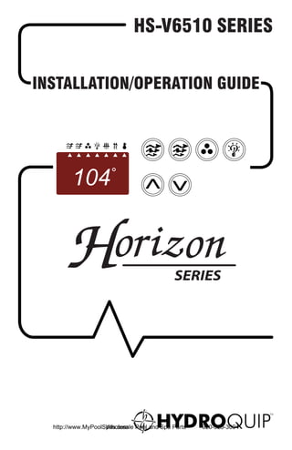
12. SPASIDE CONTROL OPERATION
These instructions apply to the ECO-3 (Large Rectangle, 6-Button panel) only, pictured
below. A mounting template can be found on page 19.
component indicators:
These triangular shaped indicator lights will illuminate when the
circuit of the affected icon is in the “on” status. For a description of
the conditions of illumination for each indicator light, please see the
icon key descriptions below.
Pump 1 Key: (If the heater setting has been set above the actual water
temperature, low speed will activate on its own as the water is heating) Press this
key once to activate the low speed of the pump; press the key a second time to
activate speed; press the key a third time to turn the pump off. The red triangle
shaped indicator in the display window below the Pump 1 icon will illuminate
while the pump is on. After 20-minutes the pump will shut off automatically
unless done so manually.
Pump 2 Key: Press this key to turn Pump 2 on and off. After 20-minutes the
pump will shut off automatically unless done manually. The red triangle shaped
indicator in the display window below the Pump 2 icon will illuminate while the
pump is on.
Air blower key: Press this key to turn Blower on and off. After 20-minutes the
blower will shut off automatically unless done manually. The red triangle shaped
indicator in the display window below the Blower icon will illuminate while the
blower is on.
Light key: Press this key to turn the light on and off. After 2-hours the light
will automatically turn off unless done manually. The red indicator in the display
window below the Light icon will illuminate while the light is on.
Temperature set keys: Press (or press & hold) the Up/Down Arrow key to
increase/decrease the water temperature. The temperature can be adjusted in
1°F increments from 59°F to 104°F (5°C to 40°C). The triangle shaped Set Point
indicator will illuminate in the display window when adjusting the temperature
then revert back to the “current” water temperature display. The triangle shaped
Heater On indicator will illuminate in the display window while the system is
heating.
Wholesale 11
http://www.MyPoolSpas.com Pool and Spa Parts 920-925-3094
13. PROGRAMMING FILTRATION
Programming Filter Cycles: Press & Hold the Pump 1 key to show the current setting.
Use the Up/Down Arrow keys to adjust the value to 1 (once a day), 2 (every 12-hours), or 3
(every 8-hours) starting the time the system is programmed.
Programming Filter Cycle Duration: Press & Hold the Light key to show the current
setting. Use the Up/Down Arrow keys to adjust the value to 60 (1-hour), 120 (2-hours),
180 (3-hours), or 480 (8-hours) per cycle. To start a filter cycle immediately, press & hold
the Light key. If no key is pressed within 5-seconds, the display will revert to the standard
monitoring mode.
* Note: If the spa is being used during the filter cycle, the cycle will be suspended for
a period of 40-minutes or until the spa is no longer in use.
OPERATIONAL CONSIDERATIONS
The following describes situation you may encounter and situations to be aware of.
Warm Weather Conditions
Since your spa will normally be expected to maintain warm to hot water ready for use, a
great deal of attention has been directed to the energy conservation detail of insulation
so as to keep electrical costs down. Energy conservation efficiency may be achieved by
extensive insulation of the skirt, plumbing and spa shell, and in some climates full foam
insulation may have been provided.
This energy conservation feature may cause an inconvenience during warmer times
of the year. During warm periods of the year, the temperature within the equipment
compartment can elevate to a point that the pump will automatically turn off for a short
period of time (15-30 minutes) to allow the pump to cool down before automatically
restarting. This cool down feature will not harm your spa but serves only to protect the
pump from damage and as an indicator that it is too hot. To minimize this occurrence,
refrain from using your Hydrotherapy Jets for prolonged periods of time during warm
seasons.
The jet pump chosen for your spa has been specifically sized for maximum performance
and your Hydrotherapy enjoyment.
It is also important to limit the operation of your air blower to 20 minutes or less so as to
minimize the temperature rise in the equipment area.
Wholesale 12
http://www.MyPoolSpas.com Pool and Spa Parts 920-925-3094
14. Filtration System
Please refer to your Spa Manufacturer’s owner’s manual regarding the operation,
maintenance, and cleaning of your filtration system.
Dirty or clogged filters can cause flow restriction and you may experience difficulty in
reaching and/or maintaining desired heat levels.
Winterizing
When freezing weather and/or power losses are expected, contact your local spa dealer
for freeze protection or winterizing recommendations for both the spa and the equipment
system. Freeze related damage is not covered by the warranty.
Chemical Water Treatment
Your dealer is familiar with local water conditions and which chemicals are compatible
with and designed specifically for your spa. This is the best person to advise you on
proper water quality management.
The one thing you can do to insure years of trouble free equipment operation is to
maintain proper water chemistry.
Two basic goals of the chemical water treatment are sanitizing and balancing the
water.
Sanitizing simply means keeping the water free from living microorganisms including
algae, bacteria, and viruses. The current most popular chemicals for sanitizing include
chlorine, bromine, and ozone.
Balancing water means establishing a balance among pH, total alkalinity, and total
hardness. Water that is unbalanced can corrode the spa and it’s support equipment or
leave deposits of minerals. Properly balanced water is essential to allow the sanitizing
chemical to work effectively. There are numerous chemical additives to help you in
controlling pH, total hardness, and total alkalinity. NEVER use softened water when filling
your spa. Softened water is extremely corrosive to metal parts of the spa equipment and
may lead to unforeseen failure.
Sometimes, despite your most diligent efforts, your water may become too far out of
balance to be managed chemically. At this point it is probably better to drain and clean the
spa and start over with fresh water.
Equipment failure caused by improper water chemistry will not be covered under
warranty.
TROUBLESHOOTING
The following describes situations and possible solutions to common problems you may
encounter as a spa owner.
Nothing Operates
Main Breaker is OFF – Set to on.
Sub-Panel Break is OFF – Set to On.
Power switch is in OFF position – Set to on.
Component(s) are not plugged in – Plug in components.
Power cord not plugged in – Plug in power cord.
Over-Heat Protection is On – Refer to page 16.
Wholesale 13
http://www.MyPoolSpas.com Pool and Spa Parts 920-925-3094
15. No, Low or Surging Water Flow
Air Lock in Plumbing System – “Bleed” the system
Restricted Flow – Insure that the water shut-off valves are open and that suction fittings are
not blocked by debris.
Dirty Filter – Clean or replace filter.
Low Water Level – Increase water level to recommended level.
No Low Speed Pump Operation
Low Level Programming Incorrect – Contact your local dealer.
Over-Heat protection On – Refer to page 16.
Pump Not Plugged- In – Plug in the pump.
No Jets or Blower Operation
Blower or Pump Not Plugged-In – Plug in the Blower or Pump.
Over-Heat Protection On – Refer to page 16.
No Therapy Jet Operation
Water Shut-off Valves are Closed – Open Shut-off valves.
Dirty Filter – Clean or replace filter.
Jets Not Properly Adjusted – Adjust jets.
Diverter Valve Not Properly Adjusted – Adjust diverter valve.
Thermal Overload Tripping – Check for restricted flow of water.
Over-Heat Protection On – Refer to page 16.
Water Leaks
Spa overfilled – Adjust water level.
Too many people in the Spa – Adjust water level.
Drain-Valve left open – Close drain valve.
Couplings or Unions Loose – Tighten or contact your local dealer.
Pump Seal Leaking – Contact your local dealer.
Plumbing Connections Leaking – Contact your local dealer.
Water Leaking from Spa side Control – Contact your local dealer.
Water in Air Blower Plumbing – Contact your local dealer.
No Heat
Temperature Not Set Correctly – Adjust Set Point.
Over-Heat Protection On – Refer to page 16.
Current limiting On – 120V Systems will not heat if High-speed or Blower is on. Contact
your Local dealer.
No Power – Reset breaker at service panel.
Low Water Flow – Clean or Replace filter.
High Heat
Temperature Sensor Not in Dry-Well – Place sensor in dry-well.
Temperature Set Too High – Adjust Set Point.
High Ambient Temperature – Remove spa cover.
Wholesale 14
http://www.MyPoolSpas.com Pool and Spa Parts 920-925-3094
16. GFCI Trips Occasionally
Lightning or Electrical Storm, Power Surge, Extreme Humid Conditions, or Radio
Frequency Interference – Reset GFCI.
NOTE: GFCI must be properly grounded and bonded.
GFCI Trips Immediately
Defective Component – Contact a qualified
service technician for assistance.
If this is a new electrical installation verify
that the electrical service is wired as
described to the right with the neutral wire
from control box attached to the neutral
terminal on the load side of the GFCI
Breaker.
No Light Operation
Light Bulb Defective – Replace bulb or contact your local dealer.
Reflector has fallen off – Replace reflector or contact your local dealer.
Light Not Plugged-In – Plug in the light.
ERROR INDICATION
To assist the user in identifying problems with the spa, the system will display an error
message. These messages will be helpful when communicating with your local dealer or
qualified technician if a problem should arise.
Pressure or Flow Switch Activated – The flow or pressure switch
is sensing water pressure or flow while the pump is not running. To clear
the error, try cycling the pump through low and high speeds. If this error
does not clear when the pump is off......
Contact your local spa dealer
Pressure or Flow switch Not Activated – The flow or pressure
switch is not sensing water pressure or flow while the pump is running. To
clear the error, try cycling the pump through low and high speeds. If this
does not clear the error, the spa filter may be dirty, possibly obstructing
water flow. If, after cleaning the filter, cycling the pump through low and
high speeds does not clear the error....
Contact your local spa dealer
Wholesale 15
http://www.MyPoolSpas.com Pool and Spa Parts 920-925-3094
17. Temperature sensor malfunction – This error will occur when
a problem with the temperature sensor exists. This error may also occur if
the system is activated while the water temperature is below 35°F. The best
thing to do when this error occurs is to....
Contact your local spa dealer
Overheat or High-Limit Protection – There are three (3) stages of
over heat:
1 – The spa water has exceeded 112°F. The heater, pump and accessory
will be deactivated until the water cools to 109°F. Be sure to check the
actual temperature with an accurate thermometer.
2 – The spa water has exceeded 119°F. The heater will deactivate while
the pump and accessory will still operate. The air blower (if equipped) can
be activated to help cool the water. WATER MUST BE BELOW 119°F AND
POWER MUST BE RESET TO CLEAR THE “HL ERROR ”
A dirty spa filter can also cause restricted flow of water, so be sure the filter
is cleaned regularly and ensure that all water shutoff valves are open.
If the system has been operating normally until now, the pump may be
overheating the spa. Refer to “Programming Filtration” on Page 12 and
reduce the duration and/or number of cycles per day.
3 – If you’ve eliminated items 1&2 as problems, the high limit sensor may
have malfunctioned If this is the case, ...
Contact your local spa dealer
Freeze Protection – There are two (2) levels of freeze protection
integrated into the system.
1 – SMART WINTER MODE, this mode will activate anytime the water
temperature falls below 59°F. This mode will be active for a period of 24
hours. In this mode, if a pump has not been activated in the last 2 hours,
the system will automatically turn it on for one (1) minute to prevent
freezing. The “Filter Cycle” indicator will illuminate while the mode is active.
2 – If the spa water temperature drops below 49°F, the heater & pump
will be activated until the water temperature reaches 50°F. While freeze
protection is active no other functions will be possible.
Wholesale 16
http://www.MyPoolSpas.com Pool and Spa Parts 920-925-3094
18. SYSTEM DATA LABEL
The system data label is located on the control box. This label is very important and
contains information you will need to establish your electrical service. The voltage and
amperage ratings are shown on the bottom of the label. Product, Model, Serial and Code
numbers are also shown on the label.
Note: This information will be necessary if you should ever have to request warranty or any
other type of service.
w w w.ho riz o npar t s.net HS-V65xx
HOR03-xxxx-
120 240
16 40/48
HQ-6000
HS-V6510-HC-LH01000 1 PHASE - 60Hz
Refer to NEC for Breaker Sizing
WARRANTY INFORMATION
To all original purchasers, Horizon Spa & Pool Parts Inc., as a distribution partner of
HydroQuip, warrants this product to be free from defects in material and workmanship for
a period of 3 years from the date of purchase.
Horizon Spa & Pool Parts Inc. will repair or replace a defective part, at our discretion.
This warranty excludes damage as a result of: normal wear, freezing, low voltage, chemical
abuse, accident, negligence, alteration, improper installation, use or care.
To obtain warranty service, contact your installing dealer within the warranty period and
have them return the defective equipment or parts to Horizon Spa & Pool Parts Inc.
The Horizon Series Limited Warranty is for service on the control box only. Purchaser is
responsible for removal or reinstallation labor, freight charges, or any other such costs
incurred in obtaining warranty service.
Horizon Spa & Pool Parts Inc. assumes no responsibility for incidental or consequential
damages. Some states do not allow the exclusion of incidental or consequential damages,
so the above limitations and exclusions may not apply to you. This warranty gives you
specific legal rights and you may also have other rights, which vary from state to state.
If you are the end user for this control system, the spa dealer may provide a different
warranty; contact your spa dealer for details and warranty information.
Wholesale 17
http://www.MyPoolSpas.com Pool and Spa Parts 920-925-3094
19. PARTS LIST
Part Number Description Control System
59-355-1098 Primary Circuit Board HS-V6510 Series (ALL)
59-355-1020 Temperature Sensor, 10ft HS-V6501-V6510 Series (ALL)
59-355-1025 Hi Limit Sensor, 14” HS-V6501-V6510 Series
59-355-1026 Hi Limit Sensor, 76” HS-V6501-V6510 Series -VH & -LH
59-355-1028 Pressure Switch Harness ALL
47-439-1295 Pressure Switch ALL
47-555-2070 Heating Element, 5.5kW, 240v ALL
60-555-1155 Fuse 20A SLO BLOW Fuse HS-V6501-V6510 Series
60-555-1157 Fuse 25A SLO BLOW Fuse HS-V6501-V6510 Series
60-555-1187 Fuse, System, 750mA HS-V6501-V6510 Series
60-555-1185 Fuse, Light, 2Amp HS-V6501-V6510 Series
60-240-1020 High Current GFCI ALL -HC
60-355-1000 Terminal Block HS-V6500 Series
60-240-1022 40A Contractor HS-V6500 Series -HC
57-315-1000 Light Bulb, 12v, Incadescent ALL
Wholesale 18
http://www.MyPoolSpas.com Pool and Spa Parts 920-925-3094
20. TOPSIDE MOUNTING
IMPORTANT - The
template on this
page is to be used
with HT-2, ECO-3, 7
& 8 series controls
ONLY. Refer to the
“Installation Manual”
for installation
details.
6 3/8”
2 5/8”
Wholesale 19
http://www.MyPoolSpas.com Pool and Spa Parts 920-925-3094
21. NOTES
Wholesale 20
http://www.MyPoolSpas.com Pool and Spa Parts 920-925-3094
22. NOTES
Wholesale 21
http://www.MyPoolSpas.com Pool and Spa Parts 920-925-3094
23. NOTES
Wholesale 22
http://www.MyPoolSpas.com Pool and Spa Parts 920-925-3094
24. 07/08 Rev. 1
http://www.MyPoolSpas.com Pool and Spa Parts
Wholesale 920-925-3094