Download as PDF, PPTX


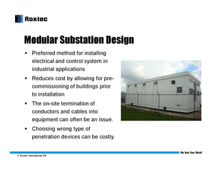
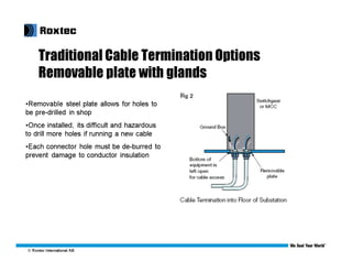

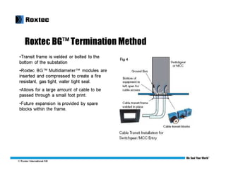


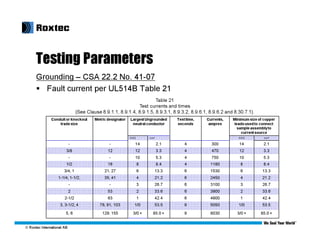
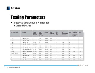

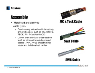

This document discusses modular substation design and cable termination options, including traditional methods and Roxtec's BGTM termination method. Some key benefits of Roxtec's method are that it allows for a large amount of cable to be passed through a small space, provides for future expansion, and testing has shown it passes grounding and bonding standards. Traditional methods can be more difficult for adding new cables later on or require removing large sections of flooring.