SlideShare a Scribd company logo
1 of 14
Download to read offline
Arid Zone Journal of Engineering, Technology and Environment. August, 2012; Vol. 8, 53-66
Copyright© Faculty of Engineering, University of Maiduguri, Nigeria.
Print ISSN: 1596-2490, Electronic ISSN: 2545-5818
www.azojete.com.ng
53
DESIGN OF A WIRELESS SENSOR NETWORK USING LPC2103
MICROCONTROLLER
Dibal, P. Y.
(Department of Computer Engineering, University of Maiduguri, Maiduguri, Nigeria)
e-mail address: yoksa77@gmail.com
Abstract
This paper deals with the design of a Wireless Sensor Network (WSN) using the LPC2103 microcontroller. The
concept of sensors and sensing in the context of sensors was introduced and the architecture of a wireless node
was described. The design approach was presented and the design was described using a diagram. The
implementation of the design was carried out using a firmware to run the WSN and achieve the desired
functionality of the WSN. Results obtained from the tests were similar to the ones obtained in the simulation. It
was concluded that based on the results obtained, the wireless node transmitted data packet in real-time to the
PC hyper-terminal. The LEDs on the wireless node were switched ON and OFF based on the value of the data
received via 14 character input. The project has been able to in practice implement and set up a basic wireless
sensor network.
Keywords: Wireless sensor, network, microcontroller, simulation
1. Introduction
Sensing can be defined as a method through which information regarding processes, physical
objects and occurrence of events are gathered. While on the other hand, a Sensor can be
defined as an object that is employed in the performance of a sensing task (Waltenegu and
Poellabauer, 2010). Sensors can be classified as either active sensors (having external power),
or as passive sensors (detecting and deriving power from the environment).
A wireless sensor (Waltenegu and Poellabauer, 2010) apart from having the sensing
component also has capabilities like communication, storage and on-board processing. Being
equipped with all these facilities, a sensor node apart from being responsible for data
collection also is responsible for analysis, correlation and fusion of its own sensor data and
data from other sensor nodes as well.
According to (Waltenegu and Poellabauer, 2010), several steps are involved in the sensing
process as shown Figure 1 below:
Figure 1: Sensing process
Dibal: Design of a wireless sensor network using LPC2103 micrcontroller. AZOJETE, 8: 53-66,
2012
54
From the fore-going therefore, we can define a wireless sensor network as a network in which
many sensors monitor large physical environments cooperatively by using wireless radios to
communicate with each other and with a base station thus making it possible for the sensors
to transmit their data to remote processing, analysis, visualization and storage systems.
The concept of a wireless sensor network according to (Pantazis and Vergados, 2007) is shown
in Figure 2 below:
2. Materials and methods
2.1 Wireless sensor architecture
The architecture of a wireless sensor (Waltenegu and Poellabauer, 2010), is shown below in
Figure 3:
Figure 2: Wireless sensor network.
Figure 3: Wireless Sensor architecture.
Arid Zone Journal of Engineering, Technology and Environment. August, 2012; Vol. 8, 53-66
55
The sensor subsystem (Waltenegu and Poellabauer, 2010), as shown in figure 3 combines
different types of physical sensors, one or more analog-to-digital (ADC) converters and a
multiplexing mechanism to share them. The output of a sensor being a continuous analog
signal is converted by the ADC to a digital format and this involves:
– quantization of the analog signal in which the number of allowable discrete values is
determined.
–determining the sampling frequency; in digital signal processing and communication
engineering, this is often determined by the Nyquist rate.
The processor subsystem (Waltenegu and Poellabauer, 2010), as shown in figure 3 forms the
core of the wireless sensor. The type of processor used is usually determined by the trade-off
between flexibility and efficiency. Possible types of processors that can be used include:
microcontrollers, digital signal processors, application specific ICs, field programmable gate
arrays (FPGAs) etc.
The LPC2103 microcontroller (LPC2103 User Manual, 2009), is the microcontroller used for
the processor subsystem of this design. The LPC2103 microcontroller is a microcontroller
that is based on the 16-bit/32-bit ARM7TDMI-S CPU and has real time-time capability
blended with 8kB, 16kB or 32kB of embedded high speed flash memory. The microcontroller
allows 32-bit code execution to be achieved at maximum clock rate because it has 128-bit
wide memory interface. This unique feature increases the performance of the interrupt service
routine (ISR) and DSP algorithms.
The pin diagram of the LPC2103 microcontroller from (LPC2103 User Manual, 2009) is
shown below in Figure 4:
Figure 4: LPC2103 pin diagram
Dibal: Design of a wireless sensor network using LPC2103 micrcontroller. AZOJETE, 8: 53-66,
2012
56
The LPC2103 microcontroller is usually housed on the MCB2103 Keil Development Board
as shown in Figure 5 below:
In the communication subsystem, as shown in figure 3, the most commonly used buses are
the Data bus, Serial-Parallel Interface (SPI) and Inter-Integrated Circuit (I2
C).
In the data bus, the Universal Asynchronous Receiver Transceiver (UART) is used for the
transmission of information. In order for the PC or user to communicate with the wireless
sensor network, a physical communication path must be established. This is achieved through
the use of the Universal Asynchronous Receiver Transmitter (UART).
UART is defined as a component (Elmenreich and Martin, 2002), which is used extensively
in serial communication. It has two basic parts: a transmitter (which is parallel-to-serial
converter) and a receiver (which is serial-to-parallel converter). To achieve accurate
connectivity, the parallel side of the UART is connected to the bus of a computer. Upon
writing a byte to the UART‟s transmit data register, the UART then begins to transmit the
byte on the serial line.
When a byte (Fang and Chen, 2011) is written to the UART‟s transmit data register for
asynchronous transmission, a “start bit” is usually added at the beginning of each word that is
scheduled for transmission. The purpose of the start bit is to alert the receiver at the other end
that a word of data is about to be transmitted, therefore ensure the clock in the receiver to be
in synchronization with that of the transmitter. To achieve an error margin of not more than
10% during transmission of the remaining bits in the word in terms of frequency drift, the
two clocks must be accurate enough. Individual data bits of the word are then transmitted
after the start bit with the Least Significant Bit (LSB) being the first to be sent. An equal
amount of time is allocated to all the bits during transmission.
A parity bit (Fang and Chen, 2011) generated by the transmitter for the purpose of error
checking is usually sent after the entire data word has been sent, after which a stop bit is sent
by the transmitter. At the receiver end, when all the data word bits have been received, the
Figure 5: MCB2103 evaluation board
Arid Zone Journal of Engineering, Technology and Environment. August, 2012; Vol. 8, 53-66
57
receiver checks for the parity bit and stop bit. If there is a failure of the stop bit to be where it
is supposed to be, the entire word is considered by the UART as garbled and a framing error
is reported to the host processor where the data was read. A typical UART frame format
according to (Fang and Chen, 2011), is shown below in Figure 6:
To address the problem of arithmetic error in baud rate setting (Elmenreich and Martin,
2002), the baud rate (BR) is set by choosing a value UBRS (UART Baud Rate Setting) as:
)2(*1 CUBRSC
f
BR clk

 (1)
where C1 and C2 are UART implementation dependant. Solving for UBRS in equation (1),
we obtain:
2
*1
C
BRC
f
UBRS clk
ideal  (2)
However, equation (2) yields a rational number for UBRS, but most UARTs only accept
UBRS values as integers. Therefore UBRS will be rounded to an integer value in
approximation of the ideal value as expressed in equation (3) below:
realUBRS 5.02
*1
 C
BRC
f clk
(3)
2.2 Design approach
The wireless sensor network will send and receive data from sensor nodes wirelessly. The
data is then transmitted to the PC wirelessly also, through a Wireless Sensor Interface (WSI).
The design approach to achieve this (WSS Manual, 2010), is shown below in Figure 7:
Figure 6: UART frame format
Figure 7: Sensors connecting to PC through wireless interface.
Dibal: Design of a wireless sensor network using LPC2103 micrcontroller. AZOJETE, 8: 53-66,
2012
58
The wireless sensor interface transmits data from the wireless sensor network to the PC.
When a sensor wants to transmit data to the PC, it does so through a Wireless Transceiver
Module (WTM), which connected to the UART interface of the LPC2103 microcontroller.
The data from the WTM is transmitted wirelessly to the WSI, which is connected to the PC
through a USB port. The data received by the PC is then displayed in a terminal interface.
The flow of data between the WSI and WTM is bidirectional.
Both the WTM and the WSI shown in Figures 8a and 8b, operate in the 433MHz frequency
band, with a supply voltage of 5V, and the Tx & Rx status LEDs. In both of them, the
PIC16F876A microcontroller is at the heart of their operation.
2.3 Implementation of the design
To achieve proper coordination of the sensor field (Figure 2), there will be a master sensor
node that will receive data from all the other sensor nodes (slave nodes), and then transmit
this data to the WSI, which is connected to the PC for display in a hyper-terminal, so that the
engineer monitoring the sensor field will know exactly what is going on.
The implementation of the design is carried out through the following steps, using Keil C and
the Microvision (Keil, 2004) IDE:
2.3.1 UART initialization
In order for the sensors to communicate properly in the wireless network, both the master
sensor node, the slave nodes, and the hyper-terminal on the PC, must all be initialized to the
same baud rate, in this case 57,600bps.
Looking at Figure 4, we can see that the UART1 Tx & Rx are located at pins P0.8 and P0.9
respectively. From (LPC2103 User Manual, 2009), we initialize two registers i.e. PINSEL0
(Pin function Selection register) and the UART1 register as shown below in code listing 1
(Figure 9):
Figure 8a: Wireless Transceiver Module Figure 8b: Wireless Sensor Interface
Arid Zone Journal of Engineering, Technology and Environment. August, 2012; Vol. 8, 53-66
59
These initialization values give a baud rate of 57,870bps, as shown below in Figure 10, which
is within the acceptable margin for error.
Next, we initialize the VIC (Vectored Interrupt Controller) register, to handle the interrupt
generated by the UART, as shown in code listing 2 (Figure 11).
2.3.2 IRQ handler
The IRQ handler is designed to handle three possible interrupts that will be generated by the
UART. These are: Receive Line Status (RLS) interrupt, Character Time-Out Indicator (CTI)
interrupt and Receive Data Available (RDA) interrupt. Of particular importance is the RDA
interrupt which is configured to be triggered once 14 characters are received. This interrupt
invokes the Receive_Packet function which is responsible for receiving the 14 character via
U1RBR. When the correct SLAVE_ID is entered, a Send_Packet function is invoked by the
RDA. The Send_Packet function transmits a data to the terminal. The RDA interrupt then
switches OFF the LEDs on the board if the first character of the Receive_Data packet is „A‟.
But, if the first character of the Receive_Data is „B‟, the RDA interrupt then switches the
LEDs ON (treating a case of one sensor responding to a command from the PC). Figure 12
shows the Code listing 3 displaying the RDA handler.
U1LCR |= 0x80; // Set DLAB with 8 bits, no parity and 1 stop bit
U1FDR = 0xC1; // UART1 fractional division register
U1DLL = 0x09; // UART1 divisor latch LSB
U1DLM = 0x00; // UART1 divisor latch MSB
U1LCR &= ~0x80; // Clear DLAB
U1IER = 0x07; // Enable UART1 RX and THRE
Interrupts
U1FCR = 0xC1; // Enable and reset TX and RX
FIFO trigger level 3
Figure 10: Initialized UART
VICVectAddr0 = (unsigned long)sio_irq; //assign address of IRQ
VICIntSelect = 0x00000000; //interrupt assigned to IRQ
VICVectCntl0 = 0x20 | 7; // UART1 Interrupt
VICIntEnable = 1 << 7; // Enable UART1
Interrupt
Figure 9: Code listing 1 - UART
initialization
Figure 11: Code listing 2 - VIC register
initialization
Dibal: Design of a wireless sensor network using LPC2103 micrcontroller. AZOJETE, 8: 53-66,
2012
60
// RDA interrupt - a complete packet has been received
else if ((IIRValue&0x07) == 0x02)
{
// Extract data and reply if slave ID matches
if((Recieve_Packet(&Recieve_Data[0])) == SLAVE_ID)
{
Send_Packet(SLAVE_ID, &Transmit_Data[0]);
if(Recieve_Data[0]=='A')
{
IOCLR0 = 0x00FF0000;
}
else if(Recieve_Data[0]=='B')
{
IOSET0 = 0x00FF0000;
}
}
}
Figure 12: Code listing 3 display of RDA handler
Arid Zone Journal of Engineering, Technology and Environment. August, 2012; Vol. 8, 53-66
61
The complete code listing for each of the wireless sensor nodes is shown in code listing 4
(Figure 13) and code listing 5 (Figure 14), respectively.
#include <LPC21xx.H> /* LPC21xx definitions */
void sio_irq (void) __irq; //Declare IRQ
void com_baudrate()
{
U1LCR |= 0x80; // Set DLAB
U1FDR = 0xFC; // Set fractional divider register
U1DLL = 0x09; // Set divisor latch LSB
U1DLM = 0x00; // Set divisor latch MSB
U1LCR &= ~0x80; // Clear DLAB
}
void init_uart (void)
{
PINSEL0 = 0x00050000; // Enable RxD1 and TxD1
U1LCR = 0x03; // 8 bits, no Parity, 1 Stop bit
U1IER = 0; // Disable UART1 Interrupts
VICVectAddr0 = (unsigned long)sio_irq; //Assign IRQ
VICIntSelect = 0x00000000; //interrupt request assigned to IRQ
VICVectCntl0 = 0x20 | 7; // UART1 Interrupt
VICIntEnable = 1 << 7; // Enable UART1 Interrupt
com_baudrate(); // setup for 57600 baud (12MHz)
U1IER = 0x07; // Enable UART1 RX and THRE Interrupts
U1FCR = 0xC1; // Enable and reset TX and RX FIFO. trigger level 3
}
int main (void)
{
init_uart (); //initialize the UART
U1THR='H'; // Send test character
U1THR='E'; // Send test character
U1THR='L'; // Send test character
U1THR='O'; // Send test character
U1THR=' '; // Send test character
IOSET0 = 0x00FF0000;
while (1) // Loop forever
{
}
}
Figure 13: Code listing 4 - Complete code listing to initialize
UART interface
Dibal: Design of a wireless sensor network using LPC2103 micrcontroller. AZOJETE, 8: 53-66,
2012
62
#include <LPC21xx.H> /* LPC21xx definitions */
#include "uart.h" /* uart definitions */
typedef unsigned char uint8_t;
// Slave ID
#define SLAVE_ID 'Z'
#define PACKET_DATA_SIZE (12U)
uint8_t Transmit_Data[PACKET_DATA_SIZE] = "FFFFFFFFFFFF";
uint8_t Recieve_Data[PACKET_DATA_SIZE];
volatile char UARTstatus;
void Send_Packet(uint8_t Slave_ID, uint8_t *Data)
{
uint8_t Checksum=0x00, i;
// Check the slave ID
if(Slave_ID > 253)
{
return;
}
// TX slave ID
U1THR = (Slave_ID);
U1THR = ' ';
// TX data
for(i=0; i<=PACKET_DATA_SIZE; i++)
{
U1THR = (Data[i]);
Checksum += Data[i];
}
// TX checksum
U1THR=' ';
U1THR=Checksum;
U1THR=' ';
}
uint8_t Recieve_Packet(uint8_t *Data)
{
uint8_t i, cChecksum=0x00, tChecksum;
uint8_t Slave_ID=0xFF;
// Get the slave ID
Slave_ID=U1RBR;
for (i=0; i<PACKET_DATA_SIZE; i++)
{
Data[i] = U1RBR;
cChecksum += Data[i];
}
// Extract the transmitted checksum
tChecksum +=U1RBR; //=cChecksum;
return(Slave_ID);
}
void sio_irq(void) __irq
{
uint8_t IIRValue, LSRValue, Dummy;
IIRValue = ((uint8_t)U1IIR >> 0x01);
LSRValue = (uint8_t)U1LSR;
IODIR0 = 0x00FF0000; //P0.16..23 defined as Outputs
// Possible error occured during transmission or reception
if ((IIRValue&0x07) == 0x03)
{
if (LSRValue & (LSR_OE | LSR_PE | LSR_FE |
LSR_RXFE | LSR_BI))
{ //there are errors, read LSR to clear the interrupt
UARTstatus = LSRValue;
Dummy += U1RBR; //dummy read;clear interrpt
}
}
// RDA interrupt - a complete packet has been recieved
else if ((IIRValue&0x07) == 0x02)
{
// Extract data and reply if slave ID matches
if ((Recieve_Packet(&Recieve_Data[0])) == SLAVE_ID)
{
Send_Packet(SLAVE_ID, &Transmit_Data[0]);
if(Recieve_Data[0]=='A')
{
IOCLR0 = 0x00FF0000;
}
else if(Recieve_Data[0]=='B')
{
IOSET0 = 0x00FF0000;
}
}
}
VICVectAddr = 0xFF; // Acknowledge Interrupt
}
Figure 14: Code listing 5 - Code for wireless sensor node
Arid Zone Journal of Engineering, Technology and Environment. August, 2012; Vol. 8, 53-66
63
3. Results and discussion
The simulation results show the output obtained from the Keil simulator after running the program.
The output presented in Figure15 shows the performance of different functions that make up the total
node program.
It can be seen from Figure 15, that the IRQ handler (sio_irq) has the highest number of calls because
it has been designed to continually run as long as 14 character input has not been fully received. The
value for the number of calls is determined by how quickly the 14 characters arrive. The
Receive_Packet function received 14 characters via U1RBR and if the characters are in the right
order, it then invokes the Send_Packet function which transmits the data.
Figure 16 shows the output obtained at the hyper-terminal as a response from the program after
getting the expected input.
When the first character of the Receive_Data packet is „A‟, the RDA interrupt turns OFF the LEDs on
the board. The test of that line code in the simulator confirms that the LEDs are switched OFF. The
simulator result is shown in Figure 17 and highlighted in red.
Figure 15: Performance analyser for node program
Figure 16: UART output at the hyper-terminal
Dibal: Design of a wireless sensor network using LPC2103 micrcontroller. AZOJETE, 8: 53-66,
2012
64
When the first character of the Receive_Data packet is „B‟, the LEDs are switched ON. Testing that
line of code on the simulator confirms the LEDs are actually switched ON (highlighted in red) as
shown in Figure 18 below:
Using flash magic, the source code was burnt to the microcontroller and the design was tested with
one of the sensor nodes. When 14 character input was made through the PC, the microcontroller
responded in real-time as expected and transmitted the predefined character to the hyper-terminal of
the PC as shown in Figure 19.
Figure 17: LEDs switched OFF
Figure 18: LEDs switched ON
Figure 19: Transmitted data packet from microcontroller to hyper-terminal
Arid Zone Journal of Engineering, Technology and Environment. August, 2012; Vol. 8, 53-66
65
During the first entry of the 14 characters, the Receive_Data had an „A‟ as its first character and the
RDA interrupt then switched OFF the LEDs on the MCB2103 board exactly as it happened in the
simulator. This is shown in Figure 20.
During the second entry of 14 characters, the Receive_Data had a „B‟ as its first character and the
RDA interrupt turned ON the LEDs on the MCB2103 board exactly as it did on the simulator. This is
shown in Figure 21 below.
4. Conclusions
The project set out with the aim of developing a wireless sensor network by writing a Keil-C
code (firmware) for transmitting a packet and then control hardware components (in this case
LEDs) on the network node. This code was tested in a simulator and the results were as
expected i.e. a packet was transmitted and the LEDs in the simulator blinked as instructed by
the firmware code.
The firmware was then downloaded to the LPC2103 microcontroller and then the
performance of the wireless sensor network was tested in real-time. The results obtained from
the test were like the results obtained in the simulation i.e. the wireless node transmitted data
packet in real-time to the PC hyper-terminal and also the LEDs on the wireless node were
switched ON and OFF based on the value of the data received via 14 character input.
Figure 20: LEDs switched OFF when Receive_Data had „A‟ as its first character
Figure 21: LEDs switched ON when Receive_Data has „B‟ as its first character
Dibal: Design of a wireless sensor network using LPC2103 micrcontroller. AZOJETE, 8: 53-66,
2012
66
References
Elmenreich, W. and Martin, D. 2002. Time-triggered communication with UARTs. 4th IEEE
International Workshop on Factory Communication Systems, pp. 97-104.
Fang, Y. and Chen, X. 2011. Design and simulation of UART, serial communication module
based on VHDL. 3rd International Workshop on Intelligent Systems and
Applications, pp. 1-4.
Keil, J.M. 2004. μVision3 IDE for Microcontrollers. Available at:
http://www.evalkits.com/files/uv3.pdf (Accessed: 29th
April 2013).
NXP 2009. LPC2101/02/03 user manual. Eindhoven: NXP.
Pantazis, N. and Vergados, D. 2007. A survey on power control issues in wireless sensor
networks. IEEE Communications Surveys and Tutorials, 9: 86-107.
Waltenegu, D. and Poellabauer, C. 2010. Fundamentals of Wireless Sensor Networks. West
Sussex: John Wiley & Sons Ltd.
Wireless Sensor System 2010. Wireless Sensor Interface. Available at:
http://77.162.55.232/usbscope/manual_wss/manual_wss.pdf (Accessed: 20th
April
2013).

More Related Content

What's hot

IJERD (www.ijerd.com) International Journal of Engineering Research and Devel...
IJERD (www.ijerd.com) International Journal of Engineering Research and Devel...IJERD (www.ijerd.com) International Journal of Engineering Research and Devel...
IJERD (www.ijerd.com) International Journal of Engineering Research and Devel...IJERD Editor
 
Embedded Tsunami Warning System
Embedded Tsunami Warning System Embedded Tsunami Warning System
Embedded Tsunami Warning System cscpconf
 
Education set for collecting and visualizing data using sensor system based ...
Education set for collecting and visualizing data using sensor  system based ...Education set for collecting and visualizing data using sensor  system based ...
Education set for collecting and visualizing data using sensor system based ...IJMER
 
Implementation of an Improved Microcontroller Based Moving Message Display Sy...
Implementation of an Improved Microcontroller Based Moving Message Display Sy...Implementation of an Improved Microcontroller Based Moving Message Display Sy...
Implementation of an Improved Microcontroller Based Moving Message Display Sy...IOSR Journals
 
A Digital Pen with a Trajectory Recognition Algorithm
A Digital Pen with a Trajectory Recognition AlgorithmA Digital Pen with a Trajectory Recognition Algorithm
A Digital Pen with a Trajectory Recognition AlgorithmIOSR Journals
 
Fpga implementation of wireless data logger system
Fpga implementation of wireless data logger systemFpga implementation of wireless data logger system
Fpga implementation of wireless data logger systemeSAT Journals
 
Maintain load balancing in wireless sensor networks using virtual grid based ...
Maintain load balancing in wireless sensor networks using virtual grid based ...Maintain load balancing in wireless sensor networks using virtual grid based ...
Maintain load balancing in wireless sensor networks using virtual grid based ...zaidinvisible
 
WSN Based Temperature Monitoring System for Multiple Locations in Industry
WSN Based Temperature Monitoring System for Multiple Locations in IndustryWSN Based Temperature Monitoring System for Multiple Locations in Industry
WSN Based Temperature Monitoring System for Multiple Locations in Industryijtsrd
 
Tracking limb motion using inertial measurement units (IMU)
Tracking limb motion using inertial measurement units (IMU)Tracking limb motion using inertial measurement units (IMU)
Tracking limb motion using inertial measurement units (IMU)IRJET Journal
 
Development and Application of a Failure Monitoring System by Using the Vibra...
Development and Application of a Failure Monitoring System by Using the Vibra...Development and Application of a Failure Monitoring System by Using the Vibra...
Development and Application of a Failure Monitoring System by Using the Vibra...inventy
 
Monitoring and Control System for Building Application Using Modbus Remote Te...
Monitoring and Control System for Building Application Using Modbus Remote Te...Monitoring and Control System for Building Application Using Modbus Remote Te...
Monitoring and Control System for Building Application Using Modbus Remote Te...IJITCA Journal
 
IRJET- Design and Implementation of Low Cost Ecg Monitoring System using Smar...
IRJET- Design and Implementation of Low Cost Ecg Monitoring System using Smar...IRJET- Design and Implementation of Low Cost Ecg Monitoring System using Smar...
IRJET- Design and Implementation of Low Cost Ecg Monitoring System using Smar...IRJET Journal
 
SMART FAULT DETECTION IN DISTRIBUTION SYSTEM
SMART FAULT DETECTION IN DISTRIBUTION SYSTEMSMART FAULT DETECTION IN DISTRIBUTION SYSTEM
SMART FAULT DETECTION IN DISTRIBUTION SYSTEMIAEME Publication
 
Process monitoring, controlling and load management system in an induction motor
Process monitoring, controlling and load management system in an induction motorProcess monitoring, controlling and load management system in an induction motor
Process monitoring, controlling and load management system in an induction motoreSAT Publishing House
 

What's hot (15)

IJERD (www.ijerd.com) International Journal of Engineering Research and Devel...
IJERD (www.ijerd.com) International Journal of Engineering Research and Devel...IJERD (www.ijerd.com) International Journal of Engineering Research and Devel...
IJERD (www.ijerd.com) International Journal of Engineering Research and Devel...
 
Embedded Tsunami Warning System
Embedded Tsunami Warning System Embedded Tsunami Warning System
Embedded Tsunami Warning System
 
Education set for collecting and visualizing data using sensor system based ...
Education set for collecting and visualizing data using sensor  system based ...Education set for collecting and visualizing data using sensor  system based ...
Education set for collecting and visualizing data using sensor system based ...
 
Implementation of an Improved Microcontroller Based Moving Message Display Sy...
Implementation of an Improved Microcontroller Based Moving Message Display Sy...Implementation of an Improved Microcontroller Based Moving Message Display Sy...
Implementation of an Improved Microcontroller Based Moving Message Display Sy...
 
A Digital Pen with a Trajectory Recognition Algorithm
A Digital Pen with a Trajectory Recognition AlgorithmA Digital Pen with a Trajectory Recognition Algorithm
A Digital Pen with a Trajectory Recognition Algorithm
 
F224450
F224450F224450
F224450
 
Fpga implementation of wireless data logger system
Fpga implementation of wireless data logger systemFpga implementation of wireless data logger system
Fpga implementation of wireless data logger system
 
Maintain load balancing in wireless sensor networks using virtual grid based ...
Maintain load balancing in wireless sensor networks using virtual grid based ...Maintain load balancing in wireless sensor networks using virtual grid based ...
Maintain load balancing in wireless sensor networks using virtual grid based ...
 
WSN Based Temperature Monitoring System for Multiple Locations in Industry
WSN Based Temperature Monitoring System for Multiple Locations in IndustryWSN Based Temperature Monitoring System for Multiple Locations in Industry
WSN Based Temperature Monitoring System for Multiple Locations in Industry
 
Tracking limb motion using inertial measurement units (IMU)
Tracking limb motion using inertial measurement units (IMU)Tracking limb motion using inertial measurement units (IMU)
Tracking limb motion using inertial measurement units (IMU)
 
Development and Application of a Failure Monitoring System by Using the Vibra...
Development and Application of a Failure Monitoring System by Using the Vibra...Development and Application of a Failure Monitoring System by Using the Vibra...
Development and Application of a Failure Monitoring System by Using the Vibra...
 
Monitoring and Control System for Building Application Using Modbus Remote Te...
Monitoring and Control System for Building Application Using Modbus Remote Te...Monitoring and Control System for Building Application Using Modbus Remote Te...
Monitoring and Control System for Building Application Using Modbus Remote Te...
 
IRJET- Design and Implementation of Low Cost Ecg Monitoring System using Smar...
IRJET- Design and Implementation of Low Cost Ecg Monitoring System using Smar...IRJET- Design and Implementation of Low Cost Ecg Monitoring System using Smar...
IRJET- Design and Implementation of Low Cost Ecg Monitoring System using Smar...
 
SMART FAULT DETECTION IN DISTRIBUTION SYSTEM
SMART FAULT DETECTION IN DISTRIBUTION SYSTEMSMART FAULT DETECTION IN DISTRIBUTION SYSTEM
SMART FAULT DETECTION IN DISTRIBUTION SYSTEM
 
Process monitoring, controlling and load management system in an induction motor
Process monitoring, controlling and load management system in an induction motorProcess monitoring, controlling and load management system in an induction motor
Process monitoring, controlling and load management system in an induction motor
 

Viewers also liked

BIM Camp Recap 2016__Modified
BIM Camp Recap 2016__ModifiedBIM Camp Recap 2016__Modified
BIM Camp Recap 2016__ModifiedTshepo G. Tau
 
STEUERRECHT - AUSBLICK AUF DAS EU - VIETNAM FREIHANDELSABKOMMEN (EVFTA)
STEUERRECHT - AUSBLICK AUF DAS EU - VIETNAM FREIHANDELSABKOMMEN (EVFTA)STEUERRECHT - AUSBLICK AUF DAS EU - VIETNAM FREIHANDELSABKOMMEN (EVFTA)
STEUERRECHT - AUSBLICK AUF DAS EU - VIETNAM FREIHANDELSABKOMMEN (EVFTA)Dr. Oliver Massmann
 
Herramientas Web.
Herramientas Web.Herramientas Web.
Herramientas Web.EmilyAntom
 
Administracion en salud tics
Administracion en salud ticsAdministracion en salud tics
Administracion en salud ticsyuli sierra
 
Cuidados del recién nacido en la unidad neonatal
Cuidados del recién nacido en la unidad neonatalCuidados del recién nacido en la unidad neonatal
Cuidados del recién nacido en la unidad neonatalJohanaMayela
 
Transportation and delivery strategy
Transportation and delivery strategyTransportation and delivery strategy
Transportation and delivery strategyAnkit
 
Traditional Vs. Social Media Prospecting
Traditional Vs. Social Media ProspectingTraditional Vs. Social Media Prospecting
Traditional Vs. Social Media Prospectingsignatureworldwide
 

Viewers also liked (12)

BIM Camp Recap 2016__Modified
BIM Camp Recap 2016__ModifiedBIM Camp Recap 2016__Modified
BIM Camp Recap 2016__Modified
 
STEUERRECHT - AUSBLICK AUF DAS EU - VIETNAM FREIHANDELSABKOMMEN (EVFTA)
STEUERRECHT - AUSBLICK AUF DAS EU - VIETNAM FREIHANDELSABKOMMEN (EVFTA)STEUERRECHT - AUSBLICK AUF DAS EU - VIETNAM FREIHANDELSABKOMMEN (EVFTA)
STEUERRECHT - AUSBLICK AUF DAS EU - VIETNAM FREIHANDELSABKOMMEN (EVFTA)
 
Herramientas Web.
Herramientas Web.Herramientas Web.
Herramientas Web.
 
Book presentation
Book presentationBook presentation
Book presentation
 
Administracion en salud tics
Administracion en salud ticsAdministracion en salud tics
Administracion en salud tics
 
Cuidados del recién nacido en la unidad neonatal
Cuidados del recién nacido en la unidad neonatalCuidados del recién nacido en la unidad neonatal
Cuidados del recién nacido en la unidad neonatal
 
Transportation and delivery strategy
Transportation and delivery strategyTransportation and delivery strategy
Transportation and delivery strategy
 
Sepsis puerperal
Sepsis puerperalSepsis puerperal
Sepsis puerperal
 
μπουκουβαλας δημητρης
μπουκουβαλας δημητρηςμπουκουβαλας δημητρης
μπουκουβαλας δημητρης
 
ψαρρας νικος
ψαρρας νικοςψαρρας νικος
ψαρρας νικος
 
Traditional Vs. Social Media Prospecting
Traditional Vs. Social Media ProspectingTraditional Vs. Social Media Prospecting
Traditional Vs. Social Media Prospecting
 
Helicobacter pylori
Helicobacter pyloriHelicobacter pylori
Helicobacter pylori
 

Similar to 6 article azojete vol 8 53 66

unit 4 smartsensors and application.pptx
unit 4 smartsensors and application.pptxunit 4 smartsensors and application.pptx
unit 4 smartsensors and application.pptxAanshuSingh3
 
Serial Communication Interface with Error Detection
Serial Communication Interface with Error DetectionSerial Communication Interface with Error Detection
Serial Communication Interface with Error Detectioniosrjce
 
IJARCCE4J s govinda Public Transport Assistant for Visually Impaired (PuTAVI)
IJARCCE4J s govinda Public Transport Assistant for Visually Impaired (PuTAVI)IJARCCE4J s govinda Public Transport Assistant for Visually Impaired (PuTAVI)
IJARCCE4J s govinda Public Transport Assistant for Visually Impaired (PuTAVI)SreekarV
 
Education set for collecting and visualizing data using sensor system based o...
Education set for collecting and visualizing data using sensor system based o...Education set for collecting and visualizing data using sensor system based o...
Education set for collecting and visualizing data using sensor system based o...IJMER
 
International Journal of Computational Engineering Research(IJCER)
International Journal of Computational Engineering Research(IJCER)International Journal of Computational Engineering Research(IJCER)
International Journal of Computational Engineering Research(IJCER)ijceronline
 
Smart Monitoring System for Substation’ Parameters and Automatic under Freque...
Smart Monitoring System for Substation’ Parameters and Automatic under Freque...Smart Monitoring System for Substation’ Parameters and Automatic under Freque...
Smart Monitoring System for Substation’ Parameters and Automatic under Freque...BRNSSPublicationHubI
 
Experimental Analysis of an Energy-Efficient WSN
Experimental Analysis of an Energy-Efficient WSNExperimental Analysis of an Energy-Efficient WSN
Experimental Analysis of an Energy-Efficient WSNidescitation
 
IRJET- Development of Data Transmission using Smart Sensing Technology for St...
IRJET- Development of Data Transmission using Smart Sensing Technology for St...IRJET- Development of Data Transmission using Smart Sensing Technology for St...
IRJET- Development of Data Transmission using Smart Sensing Technology for St...IRJET Journal
 
International Journal of Computational Engineering Research(IJCER)
International Journal of Computational Engineering Research(IJCER)International Journal of Computational Engineering Research(IJCER)
International Journal of Computational Engineering Research(IJCER)ijceronline
 
SOCIAL NETWORK FOR SMART DEVICES USING EMBEDDED ETHERNET
SOCIAL NETWORK FOR SMART DEVICES USING EMBEDDED ETHERNETSOCIAL NETWORK FOR SMART DEVICES USING EMBEDDED ETHERNET
SOCIAL NETWORK FOR SMART DEVICES USING EMBEDDED ETHERNETcseij
 
A ZigBee Based Wireless Sensor Network for an Agricultural Environment
A ZigBee Based Wireless Sensor Network for an Agricultural EnvironmentA ZigBee Based Wireless Sensor Network for an Agricultural Environment
A ZigBee Based Wireless Sensor Network for an Agricultural Environmentijsrd.com
 
Bus Data Acquisition and Remote Monitoring System Using Gsm & Can
Bus Data Acquisition and Remote Monitoring System Using Gsm & CanBus Data Acquisition and Remote Monitoring System Using Gsm & Can
Bus Data Acquisition and Remote Monitoring System Using Gsm & CanIOSR Journals
 
LORA BASED DATA ACQUISITION SYSTEM
LORA BASED DATA ACQUISITION SYSTEMLORA BASED DATA ACQUISITION SYSTEM
LORA BASED DATA ACQUISITION SYSTEMIRJET Journal
 
A novel Ethernet based processing system for remote source harmonic detection
A novel Ethernet based processing system for remote source harmonic detectionA novel Ethernet based processing system for remote source harmonic detection
A novel Ethernet based processing system for remote source harmonic detectionTELKOMNIKA JOURNAL
 
Adaptive Monitoring and Localization of Faulty Node in a Wireless Sensor Netw...
Adaptive Monitoring and Localization of Faulty Node in a Wireless Sensor Netw...Adaptive Monitoring and Localization of Faulty Node in a Wireless Sensor Netw...
Adaptive Monitoring and Localization of Faulty Node in a Wireless Sensor Netw...Onyebuchi nosiri
 

Similar to 6 article azojete vol 8 53 66 (20)

E010113235
E010113235E010113235
E010113235
 
unit 4 smartsensors and application.pptx
unit 4 smartsensors and application.pptxunit 4 smartsensors and application.pptx
unit 4 smartsensors and application.pptx
 
Serial Communication Interface with Error Detection
Serial Communication Interface with Error DetectionSerial Communication Interface with Error Detection
Serial Communication Interface with Error Detection
 
M010617376
M010617376M010617376
M010617376
 
IJARCCE4J s govinda Public Transport Assistant for Visually Impaired (PuTAVI)
IJARCCE4J s govinda Public Transport Assistant for Visually Impaired (PuTAVI)IJARCCE4J s govinda Public Transport Assistant for Visually Impaired (PuTAVI)
IJARCCE4J s govinda Public Transport Assistant for Visually Impaired (PuTAVI)
 
Education set for collecting and visualizing data using sensor system based o...
Education set for collecting and visualizing data using sensor system based o...Education set for collecting and visualizing data using sensor system based o...
Education set for collecting and visualizing data using sensor system based o...
 
International Journal of Computational Engineering Research(IJCER)
International Journal of Computational Engineering Research(IJCER)International Journal of Computational Engineering Research(IJCER)
International Journal of Computational Engineering Research(IJCER)
 
Smart Monitoring System for Substation’ Parameters and Automatic under Freque...
Smart Monitoring System for Substation’ Parameters and Automatic under Freque...Smart Monitoring System for Substation’ Parameters and Automatic under Freque...
Smart Monitoring System for Substation’ Parameters and Automatic under Freque...
 
Experimental Analysis of an Energy-Efficient WSN
Experimental Analysis of an Energy-Efficient WSNExperimental Analysis of an Energy-Efficient WSN
Experimental Analysis of an Energy-Efficient WSN
 
B41012015
B41012015B41012015
B41012015
 
IRJET- Development of Data Transmission using Smart Sensing Technology for St...
IRJET- Development of Data Transmission using Smart Sensing Technology for St...IRJET- Development of Data Transmission using Smart Sensing Technology for St...
IRJET- Development of Data Transmission using Smart Sensing Technology for St...
 
International Journal of Computational Engineering Research(IJCER)
International Journal of Computational Engineering Research(IJCER)International Journal of Computational Engineering Research(IJCER)
International Journal of Computational Engineering Research(IJCER)
 
SOCIAL NETWORK FOR SMART DEVICES USING EMBEDDED ETHERNET
SOCIAL NETWORK FOR SMART DEVICES USING EMBEDDED ETHERNETSOCIAL NETWORK FOR SMART DEVICES USING EMBEDDED ETHERNET
SOCIAL NETWORK FOR SMART DEVICES USING EMBEDDED ETHERNET
 
A ZigBee Based Wireless Sensor Network for an Agricultural Environment
A ZigBee Based Wireless Sensor Network for an Agricultural EnvironmentA ZigBee Based Wireless Sensor Network for an Agricultural Environment
A ZigBee Based Wireless Sensor Network for an Agricultural Environment
 
Bus Data Acquisition and Remote Monitoring System Using Gsm & Can
Bus Data Acquisition and Remote Monitoring System Using Gsm & CanBus Data Acquisition and Remote Monitoring System Using Gsm & Can
Bus Data Acquisition and Remote Monitoring System Using Gsm & Can
 
LORA BASED DATA ACQUISITION SYSTEM
LORA BASED DATA ACQUISITION SYSTEMLORA BASED DATA ACQUISITION SYSTEM
LORA BASED DATA ACQUISITION SYSTEM
 
A novel Ethernet based processing system for remote source harmonic detection
A novel Ethernet based processing system for remote source harmonic detectionA novel Ethernet based processing system for remote source harmonic detection
A novel Ethernet based processing system for remote source harmonic detection
 
Controller Area Network for Monitoring and Controlling the Industrial Paramet...
Controller Area Network for Monitoring and Controlling the Industrial Paramet...Controller Area Network for Monitoring and Controlling the Industrial Paramet...
Controller Area Network for Monitoring and Controlling the Industrial Paramet...
 
Wireless Data Transfer in Under Water System
Wireless Data Transfer in Under Water SystemWireless Data Transfer in Under Water System
Wireless Data Transfer in Under Water System
 
Adaptive Monitoring and Localization of Faulty Node in a Wireless Sensor Netw...
Adaptive Monitoring and Localization of Faulty Node in a Wireless Sensor Netw...Adaptive Monitoring and Localization of Faulty Node in a Wireless Sensor Netw...
Adaptive Monitoring and Localization of Faulty Node in a Wireless Sensor Netw...
 

More from Oyeniyi Samuel

Particle Swarm Optimization (PSO)-Based Distributed Power Control Algorithm f...
Particle Swarm Optimization (PSO)-Based Distributed Power Control Algorithm f...Particle Swarm Optimization (PSO)-Based Distributed Power Control Algorithm f...
Particle Swarm Optimization (PSO)-Based Distributed Power Control Algorithm f...Oyeniyi Samuel
 
Equilibrium and Kinetic Studies of Adsorption of Safranin-O from Aqueous Solu...
Equilibrium and Kinetic Studies of Adsorption of Safranin-O from Aqueous Solu...Equilibrium and Kinetic Studies of Adsorption of Safranin-O from Aqueous Solu...
Equilibrium and Kinetic Studies of Adsorption of Safranin-O from Aqueous Solu...Oyeniyi Samuel
 
Design Description of a Tentacle Based Scanning System
Design Description of a Tentacle Based Scanning SystemDesign Description of a Tentacle Based Scanning System
Design Description of a Tentacle Based Scanning SystemOyeniyi Samuel
 
Profiled Deck Composite Slab Strength Verification: A Review
Profiled Deck Composite Slab Strength Verification: A ReviewProfiled Deck Composite Slab Strength Verification: A Review
Profiled Deck Composite Slab Strength Verification: A ReviewOyeniyi Samuel
 
Optimization of Mechanical Expression of Castor Seeds Oil (Ricinus communis) ...
Optimization of Mechanical Expression of Castor Seeds Oil (Ricinus communis) ...Optimization of Mechanical Expression of Castor Seeds Oil (Ricinus communis) ...
Optimization of Mechanical Expression of Castor Seeds Oil (Ricinus communis) ...Oyeniyi Samuel
 
Inundation and Hazard Mapping on River Asa, using GIS
Inundation and Hazard Mapping on River Asa, using GISInundation and Hazard Mapping on River Asa, using GIS
Inundation and Hazard Mapping on River Asa, using GISOyeniyi Samuel
 
A Review of Smart Grids Deployment Issues in Developing Countries
A Review of Smart Grids Deployment Issues in Developing CountriesA Review of Smart Grids Deployment Issues in Developing Countries
A Review of Smart Grids Deployment Issues in Developing CountriesOyeniyi Samuel
 
NOx Emission in Iron and Steel Production: A Review of Control Measures for S...
NOx Emission in Iron and Steel Production: A Review of Control Measures for S...NOx Emission in Iron and Steel Production: A Review of Control Measures for S...
NOx Emission in Iron and Steel Production: A Review of Control Measures for S...Oyeniyi Samuel
 
Artificial Neural Network Modelling of the Energy Content of Municipal Solid ...
Artificial Neural Network Modelling of the Energy Content of Municipal Solid ...Artificial Neural Network Modelling of the Energy Content of Municipal Solid ...
Artificial Neural Network Modelling of the Energy Content of Municipal Solid ...Oyeniyi Samuel
 
Development of Inundation Map for Hypothetical Asa Dam Break using HEC-RAS an...
Development of Inundation Map for Hypothetical Asa Dam Break using HEC-RAS an...Development of Inundation Map for Hypothetical Asa Dam Break using HEC-RAS an...
Development of Inundation Map for Hypothetical Asa Dam Break using HEC-RAS an...Oyeniyi Samuel
 
Job Safety Assessment of Woodwork Industry in the South-western Nigeria
Job Safety Assessment of Woodwork Industry in the South-western NigeriaJob Safety Assessment of Woodwork Industry in the South-western Nigeria
Job Safety Assessment of Woodwork Industry in the South-western NigeriaOyeniyi Samuel
 
Anaerobicaly - Composted Environmental Wastes as Organic Fertilizer and Ident...
Anaerobicaly - Composted Environmental Wastes as Organic Fertilizer and Ident...Anaerobicaly - Composted Environmental Wastes as Organic Fertilizer and Ident...
Anaerobicaly - Composted Environmental Wastes as Organic Fertilizer and Ident...Oyeniyi Samuel
 
Security Architecture for Thin Client Network
Security Architecture for Thin Client NetworkSecurity Architecture for Thin Client Network
Security Architecture for Thin Client NetworkOyeniyi Samuel
 
Algorithm for the Dynamic Analysis of Plane Rectangular Rigid Frame Subjected...
Algorithm for the Dynamic Analysis of Plane Rectangular Rigid Frame Subjected...Algorithm for the Dynamic Analysis of Plane Rectangular Rigid Frame Subjected...
Algorithm for the Dynamic Analysis of Plane Rectangular Rigid Frame Subjected...Oyeniyi Samuel
 
Comparism of the Properties and Yield of Bioethanol from Mango and Orange Waste
Comparism of the Properties and Yield of Bioethanol from Mango and Orange WasteComparism of the Properties and Yield of Bioethanol from Mango and Orange Waste
Comparism of the Properties and Yield of Bioethanol from Mango and Orange WasteOyeniyi Samuel
 
Development of Farm Records Software
Development of Farm Records SoftwareDevelopment of Farm Records Software
Development of Farm Records SoftwareOyeniyi Samuel
 
Compressive Strength of Concrete made from Natural Fine Aggregate Sources in ...
Compressive Strength of Concrete made from Natural Fine Aggregate Sources in ...Compressive Strength of Concrete made from Natural Fine Aggregate Sources in ...
Compressive Strength of Concrete made from Natural Fine Aggregate Sources in ...Oyeniyi Samuel
 
Evaluation of Chemical and Physico-Mechanical Properties of Ado-Ekiti Natural...
Evaluation of Chemical and Physico-Mechanical Properties of Ado-Ekiti Natural...Evaluation of Chemical and Physico-Mechanical Properties of Ado-Ekiti Natural...
Evaluation of Chemical and Physico-Mechanical Properties of Ado-Ekiti Natural...Oyeniyi Samuel
 
Modeling and Simulation of Pyrolysis Process for a Beech Wood Material
Modeling and Simulation of Pyrolysis Process for a Beech Wood MaterialModeling and Simulation of Pyrolysis Process for a Beech Wood Material
Modeling and Simulation of Pyrolysis Process for a Beech Wood MaterialOyeniyi Samuel
 
An Investigation into the Effectiveness of Machine Learning Techniques for In...
An Investigation into the Effectiveness of Machine Learning Techniques for In...An Investigation into the Effectiveness of Machine Learning Techniques for In...
An Investigation into the Effectiveness of Machine Learning Techniques for In...Oyeniyi Samuel
 

More from Oyeniyi Samuel (20)

Particle Swarm Optimization (PSO)-Based Distributed Power Control Algorithm f...
Particle Swarm Optimization (PSO)-Based Distributed Power Control Algorithm f...Particle Swarm Optimization (PSO)-Based Distributed Power Control Algorithm f...
Particle Swarm Optimization (PSO)-Based Distributed Power Control Algorithm f...
 
Equilibrium and Kinetic Studies of Adsorption of Safranin-O from Aqueous Solu...
Equilibrium and Kinetic Studies of Adsorption of Safranin-O from Aqueous Solu...Equilibrium and Kinetic Studies of Adsorption of Safranin-O from Aqueous Solu...
Equilibrium and Kinetic Studies of Adsorption of Safranin-O from Aqueous Solu...
 
Design Description of a Tentacle Based Scanning System
Design Description of a Tentacle Based Scanning SystemDesign Description of a Tentacle Based Scanning System
Design Description of a Tentacle Based Scanning System
 
Profiled Deck Composite Slab Strength Verification: A Review
Profiled Deck Composite Slab Strength Verification: A ReviewProfiled Deck Composite Slab Strength Verification: A Review
Profiled Deck Composite Slab Strength Verification: A Review
 
Optimization of Mechanical Expression of Castor Seeds Oil (Ricinus communis) ...
Optimization of Mechanical Expression of Castor Seeds Oil (Ricinus communis) ...Optimization of Mechanical Expression of Castor Seeds Oil (Ricinus communis) ...
Optimization of Mechanical Expression of Castor Seeds Oil (Ricinus communis) ...
 
Inundation and Hazard Mapping on River Asa, using GIS
Inundation and Hazard Mapping on River Asa, using GISInundation and Hazard Mapping on River Asa, using GIS
Inundation and Hazard Mapping on River Asa, using GIS
 
A Review of Smart Grids Deployment Issues in Developing Countries
A Review of Smart Grids Deployment Issues in Developing CountriesA Review of Smart Grids Deployment Issues in Developing Countries
A Review of Smart Grids Deployment Issues in Developing Countries
 
NOx Emission in Iron and Steel Production: A Review of Control Measures for S...
NOx Emission in Iron and Steel Production: A Review of Control Measures for S...NOx Emission in Iron and Steel Production: A Review of Control Measures for S...
NOx Emission in Iron and Steel Production: A Review of Control Measures for S...
 
Artificial Neural Network Modelling of the Energy Content of Municipal Solid ...
Artificial Neural Network Modelling of the Energy Content of Municipal Solid ...Artificial Neural Network Modelling of the Energy Content of Municipal Solid ...
Artificial Neural Network Modelling of the Energy Content of Municipal Solid ...
 
Development of Inundation Map for Hypothetical Asa Dam Break using HEC-RAS an...
Development of Inundation Map for Hypothetical Asa Dam Break using HEC-RAS an...Development of Inundation Map for Hypothetical Asa Dam Break using HEC-RAS an...
Development of Inundation Map for Hypothetical Asa Dam Break using HEC-RAS an...
 
Job Safety Assessment of Woodwork Industry in the South-western Nigeria
Job Safety Assessment of Woodwork Industry in the South-western NigeriaJob Safety Assessment of Woodwork Industry in the South-western Nigeria
Job Safety Assessment of Woodwork Industry in the South-western Nigeria
 
Anaerobicaly - Composted Environmental Wastes as Organic Fertilizer and Ident...
Anaerobicaly - Composted Environmental Wastes as Organic Fertilizer and Ident...Anaerobicaly - Composted Environmental Wastes as Organic Fertilizer and Ident...
Anaerobicaly - Composted Environmental Wastes as Organic Fertilizer and Ident...
 
Security Architecture for Thin Client Network
Security Architecture for Thin Client NetworkSecurity Architecture for Thin Client Network
Security Architecture for Thin Client Network
 
Algorithm for the Dynamic Analysis of Plane Rectangular Rigid Frame Subjected...
Algorithm for the Dynamic Analysis of Plane Rectangular Rigid Frame Subjected...Algorithm for the Dynamic Analysis of Plane Rectangular Rigid Frame Subjected...
Algorithm for the Dynamic Analysis of Plane Rectangular Rigid Frame Subjected...
 
Comparism of the Properties and Yield of Bioethanol from Mango and Orange Waste
Comparism of the Properties and Yield of Bioethanol from Mango and Orange WasteComparism of the Properties and Yield of Bioethanol from Mango and Orange Waste
Comparism of the Properties and Yield of Bioethanol from Mango and Orange Waste
 
Development of Farm Records Software
Development of Farm Records SoftwareDevelopment of Farm Records Software
Development of Farm Records Software
 
Compressive Strength of Concrete made from Natural Fine Aggregate Sources in ...
Compressive Strength of Concrete made from Natural Fine Aggregate Sources in ...Compressive Strength of Concrete made from Natural Fine Aggregate Sources in ...
Compressive Strength of Concrete made from Natural Fine Aggregate Sources in ...
 
Evaluation of Chemical and Physico-Mechanical Properties of Ado-Ekiti Natural...
Evaluation of Chemical and Physico-Mechanical Properties of Ado-Ekiti Natural...Evaluation of Chemical and Physico-Mechanical Properties of Ado-Ekiti Natural...
Evaluation of Chemical and Physico-Mechanical Properties of Ado-Ekiti Natural...
 
Modeling and Simulation of Pyrolysis Process for a Beech Wood Material
Modeling and Simulation of Pyrolysis Process for a Beech Wood MaterialModeling and Simulation of Pyrolysis Process for a Beech Wood Material
Modeling and Simulation of Pyrolysis Process for a Beech Wood Material
 
An Investigation into the Effectiveness of Machine Learning Techniques for In...
An Investigation into the Effectiveness of Machine Learning Techniques for In...An Investigation into the Effectiveness of Machine Learning Techniques for In...
An Investigation into the Effectiveness of Machine Learning Techniques for In...
 

Recently uploaded

Call Us ≽ 8377877756 ≼ Call Girls In Shastri Nagar (Delhi)
Call Us ≽ 8377877756 ≼ Call Girls In Shastri Nagar (Delhi)Call Us ≽ 8377877756 ≼ Call Girls In Shastri Nagar (Delhi)
Call Us ≽ 8377877756 ≼ Call Girls In Shastri Nagar (Delhi)dollysharma2066
 
main PPT.pptx of girls hostel security using rfid
main PPT.pptx of girls hostel security using rfidmain PPT.pptx of girls hostel security using rfid
main PPT.pptx of girls hostel security using rfidNikhilNagaraju
 
CCS355 Neural Network & Deep Learning UNIT III notes and Question bank .pdf
CCS355 Neural Network & Deep Learning UNIT III notes and Question bank .pdfCCS355 Neural Network & Deep Learning UNIT III notes and Question bank .pdf
CCS355 Neural Network & Deep Learning UNIT III notes and Question bank .pdfAsst.prof M.Gokilavani
 
SPICE PARK APR2024 ( 6,793 SPICE Models )
SPICE PARK APR2024 ( 6,793 SPICE Models )SPICE PARK APR2024 ( 6,793 SPICE Models )
SPICE PARK APR2024 ( 6,793 SPICE Models )Tsuyoshi Horigome
 
APPLICATIONS-AC/DC DRIVES-OPERATING CHARACTERISTICS
APPLICATIONS-AC/DC DRIVES-OPERATING CHARACTERISTICSAPPLICATIONS-AC/DC DRIVES-OPERATING CHARACTERISTICS
APPLICATIONS-AC/DC DRIVES-OPERATING CHARACTERISTICSKurinjimalarL3
 
Past, Present and Future of Generative AI
Past, Present and Future of Generative AIPast, Present and Future of Generative AI
Past, Present and Future of Generative AIabhishek36461
 
Gurgaon ✡️9711147426✨Call In girls Gurgaon Sector 51 escort service
Gurgaon ✡️9711147426✨Call In girls Gurgaon Sector 51 escort serviceGurgaon ✡️9711147426✨Call In girls Gurgaon Sector 51 escort service
Gurgaon ✡️9711147426✨Call In girls Gurgaon Sector 51 escort servicejennyeacort
 
Gfe Mayur Vihar Call Girls Service WhatsApp -> 9999965857 Available 24x7 ^ De...
Gfe Mayur Vihar Call Girls Service WhatsApp -> 9999965857 Available 24x7 ^ De...Gfe Mayur Vihar Call Girls Service WhatsApp -> 9999965857 Available 24x7 ^ De...
Gfe Mayur Vihar Call Girls Service WhatsApp -> 9999965857 Available 24x7 ^ De...srsj9000
 
Decoding Kotlin - Your guide to solving the mysterious in Kotlin.pptx
Decoding Kotlin - Your guide to solving the mysterious in Kotlin.pptxDecoding Kotlin - Your guide to solving the mysterious in Kotlin.pptx
Decoding Kotlin - Your guide to solving the mysterious in Kotlin.pptxJoão Esperancinha
 
Introduction to Microprocesso programming and interfacing.pptx
Introduction to Microprocesso programming and interfacing.pptxIntroduction to Microprocesso programming and interfacing.pptx
Introduction to Microprocesso programming and interfacing.pptxvipinkmenon1
 
HARMONY IN THE HUMAN BEING - Unit-II UHV-2
HARMONY IN THE HUMAN BEING - Unit-II UHV-2HARMONY IN THE HUMAN BEING - Unit-II UHV-2
HARMONY IN THE HUMAN BEING - Unit-II UHV-2RajaP95
 
INFLUENCE OF NANOSILICA ON THE PROPERTIES OF CONCRETE
INFLUENCE OF NANOSILICA ON THE PROPERTIES OF CONCRETEINFLUENCE OF NANOSILICA ON THE PROPERTIES OF CONCRETE
INFLUENCE OF NANOSILICA ON THE PROPERTIES OF CONCRETEroselinkalist12
 
Electronically Controlled suspensions system .pdf
Electronically Controlled suspensions system .pdfElectronically Controlled suspensions system .pdf
Electronically Controlled suspensions system .pdfme23b1001
 
Application of Residue Theorem to evaluate real integrations.pptx
Application of Residue Theorem to evaluate real integrations.pptxApplication of Residue Theorem to evaluate real integrations.pptx
Application of Residue Theorem to evaluate real integrations.pptx959SahilShah
 
power system scada applications and uses
power system scada applications and usespower system scada applications and uses
power system scada applications and usesDevarapalliHaritha
 
Artificial-Intelligence-in-Electronics (K).pptx
Artificial-Intelligence-in-Electronics (K).pptxArtificial-Intelligence-in-Electronics (K).pptx
Artificial-Intelligence-in-Electronics (K).pptxbritheesh05
 
What are the advantages and disadvantages of membrane structures.pptx
What are the advantages and disadvantages of membrane structures.pptxWhat are the advantages and disadvantages of membrane structures.pptx
What are the advantages and disadvantages of membrane structures.pptxwendy cai
 

Recently uploaded (20)

Call Us ≽ 8377877756 ≼ Call Girls In Shastri Nagar (Delhi)
Call Us ≽ 8377877756 ≼ Call Girls In Shastri Nagar (Delhi)Call Us ≽ 8377877756 ≼ Call Girls In Shastri Nagar (Delhi)
Call Us ≽ 8377877756 ≼ Call Girls In Shastri Nagar (Delhi)
 
main PPT.pptx of girls hostel security using rfid
main PPT.pptx of girls hostel security using rfidmain PPT.pptx of girls hostel security using rfid
main PPT.pptx of girls hostel security using rfid
 
young call girls in Rajiv Chowk🔝 9953056974 🔝 Delhi escort Service
young call girls in Rajiv Chowk🔝 9953056974 🔝 Delhi escort Serviceyoung call girls in Rajiv Chowk🔝 9953056974 🔝 Delhi escort Service
young call girls in Rajiv Chowk🔝 9953056974 🔝 Delhi escort Service
 
CCS355 Neural Network & Deep Learning UNIT III notes and Question bank .pdf
CCS355 Neural Network & Deep Learning UNIT III notes and Question bank .pdfCCS355 Neural Network & Deep Learning UNIT III notes and Question bank .pdf
CCS355 Neural Network & Deep Learning UNIT III notes and Question bank .pdf
 
SPICE PARK APR2024 ( 6,793 SPICE Models )
SPICE PARK APR2024 ( 6,793 SPICE Models )SPICE PARK APR2024 ( 6,793 SPICE Models )
SPICE PARK APR2024 ( 6,793 SPICE Models )
 
APPLICATIONS-AC/DC DRIVES-OPERATING CHARACTERISTICS
APPLICATIONS-AC/DC DRIVES-OPERATING CHARACTERISTICSAPPLICATIONS-AC/DC DRIVES-OPERATING CHARACTERISTICS
APPLICATIONS-AC/DC DRIVES-OPERATING CHARACTERISTICS
 
Past, Present and Future of Generative AI
Past, Present and Future of Generative AIPast, Present and Future of Generative AI
Past, Present and Future of Generative AI
 
★ CALL US 9953330565 ( HOT Young Call Girls In Badarpur delhi NCR
★ CALL US 9953330565 ( HOT Young Call Girls In Badarpur delhi NCR★ CALL US 9953330565 ( HOT Young Call Girls In Badarpur delhi NCR
★ CALL US 9953330565 ( HOT Young Call Girls In Badarpur delhi NCR
 
Gurgaon ✡️9711147426✨Call In girls Gurgaon Sector 51 escort service
Gurgaon ✡️9711147426✨Call In girls Gurgaon Sector 51 escort serviceGurgaon ✡️9711147426✨Call In girls Gurgaon Sector 51 escort service
Gurgaon ✡️9711147426✨Call In girls Gurgaon Sector 51 escort service
 
Gfe Mayur Vihar Call Girls Service WhatsApp -> 9999965857 Available 24x7 ^ De...
Gfe Mayur Vihar Call Girls Service WhatsApp -> 9999965857 Available 24x7 ^ De...Gfe Mayur Vihar Call Girls Service WhatsApp -> 9999965857 Available 24x7 ^ De...
Gfe Mayur Vihar Call Girls Service WhatsApp -> 9999965857 Available 24x7 ^ De...
 
Decoding Kotlin - Your guide to solving the mysterious in Kotlin.pptx
Decoding Kotlin - Your guide to solving the mysterious in Kotlin.pptxDecoding Kotlin - Your guide to solving the mysterious in Kotlin.pptx
Decoding Kotlin - Your guide to solving the mysterious in Kotlin.pptx
 
Introduction to Microprocesso programming and interfacing.pptx
Introduction to Microprocesso programming and interfacing.pptxIntroduction to Microprocesso programming and interfacing.pptx
Introduction to Microprocesso programming and interfacing.pptx
 
HARMONY IN THE HUMAN BEING - Unit-II UHV-2
HARMONY IN THE HUMAN BEING - Unit-II UHV-2HARMONY IN THE HUMAN BEING - Unit-II UHV-2
HARMONY IN THE HUMAN BEING - Unit-II UHV-2
 
INFLUENCE OF NANOSILICA ON THE PROPERTIES OF CONCRETE
INFLUENCE OF NANOSILICA ON THE PROPERTIES OF CONCRETEINFLUENCE OF NANOSILICA ON THE PROPERTIES OF CONCRETE
INFLUENCE OF NANOSILICA ON THE PROPERTIES OF CONCRETE
 
Electronically Controlled suspensions system .pdf
Electronically Controlled suspensions system .pdfElectronically Controlled suspensions system .pdf
Electronically Controlled suspensions system .pdf
 
Application of Residue Theorem to evaluate real integrations.pptx
Application of Residue Theorem to evaluate real integrations.pptxApplication of Residue Theorem to evaluate real integrations.pptx
Application of Residue Theorem to evaluate real integrations.pptx
 
power system scada applications and uses
power system scada applications and usespower system scada applications and uses
power system scada applications and uses
 
Artificial-Intelligence-in-Electronics (K).pptx
Artificial-Intelligence-in-Electronics (K).pptxArtificial-Intelligence-in-Electronics (K).pptx
Artificial-Intelligence-in-Electronics (K).pptx
 
What are the advantages and disadvantages of membrane structures.pptx
What are the advantages and disadvantages of membrane structures.pptxWhat are the advantages and disadvantages of membrane structures.pptx
What are the advantages and disadvantages of membrane structures.pptx
 
Call Us -/9953056974- Call Girls In Vikaspuri-/- Delhi NCR
Call Us -/9953056974- Call Girls In Vikaspuri-/- Delhi NCRCall Us -/9953056974- Call Girls In Vikaspuri-/- Delhi NCR
Call Us -/9953056974- Call Girls In Vikaspuri-/- Delhi NCR
 

6 article azojete vol 8 53 66

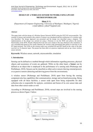
  • 1. Arid Zone Journal of Engineering, Technology and Environment. August, 2012; Vol. 8, 53-66 Copyright© Faculty of Engineering, University of Maiduguri, Nigeria. Print ISSN: 1596-2490, Electronic ISSN: 2545-5818 www.azojete.com.ng 53 DESIGN OF A WIRELESS SENSOR NETWORK USING LPC2103 MICROCONTROLLER Dibal, P. Y. (Department of Computer Engineering, University of Maiduguri, Maiduguri, Nigeria) e-mail address: yoksa77@gmail.com Abstract This paper deals with the design of a Wireless Sensor Network (WSN) using the LPC2103 microcontroller. The concept of sensors and sensing in the context of sensors was introduced and the architecture of a wireless node was described. The design approach was presented and the design was described using a diagram. The implementation of the design was carried out using a firmware to run the WSN and achieve the desired functionality of the WSN. Results obtained from the tests were similar to the ones obtained in the simulation. It was concluded that based on the results obtained, the wireless node transmitted data packet in real-time to the PC hyper-terminal. The LEDs on the wireless node were switched ON and OFF based on the value of the data received via 14 character input. The project has been able to in practice implement and set up a basic wireless sensor network. Keywords: Wireless sensor, network, microcontroller, simulation 1. Introduction Sensing can be defined as a method through which information regarding processes, physical objects and occurrence of events are gathered. While on the other hand, a Sensor can be defined as an object that is employed in the performance of a sensing task (Waltenegu and Poellabauer, 2010). Sensors can be classified as either active sensors (having external power), or as passive sensors (detecting and deriving power from the environment). A wireless sensor (Waltenegu and Poellabauer, 2010) apart from having the sensing component also has capabilities like communication, storage and on-board processing. Being equipped with all these facilities, a sensor node apart from being responsible for data collection also is responsible for analysis, correlation and fusion of its own sensor data and data from other sensor nodes as well. According to (Waltenegu and Poellabauer, 2010), several steps are involved in the sensing process as shown Figure 1 below: Figure 1: Sensing process
  • 2. Dibal: Design of a wireless sensor network using LPC2103 micrcontroller. AZOJETE, 8: 53-66, 2012 54 From the fore-going therefore, we can define a wireless sensor network as a network in which many sensors monitor large physical environments cooperatively by using wireless radios to communicate with each other and with a base station thus making it possible for the sensors to transmit their data to remote processing, analysis, visualization and storage systems. The concept of a wireless sensor network according to (Pantazis and Vergados, 2007) is shown in Figure 2 below: 2. Materials and methods 2.1 Wireless sensor architecture The architecture of a wireless sensor (Waltenegu and Poellabauer, 2010), is shown below in Figure 3: Figure 2: Wireless sensor network. Figure 3: Wireless Sensor architecture.
  • 3. Arid Zone Journal of Engineering, Technology and Environment. August, 2012; Vol. 8, 53-66 55 The sensor subsystem (Waltenegu and Poellabauer, 2010), as shown in figure 3 combines different types of physical sensors, one or more analog-to-digital (ADC) converters and a multiplexing mechanism to share them. The output of a sensor being a continuous analog signal is converted by the ADC to a digital format and this involves: – quantization of the analog signal in which the number of allowable discrete values is determined. –determining the sampling frequency; in digital signal processing and communication engineering, this is often determined by the Nyquist rate. The processor subsystem (Waltenegu and Poellabauer, 2010), as shown in figure 3 forms the core of the wireless sensor. The type of processor used is usually determined by the trade-off between flexibility and efficiency. Possible types of processors that can be used include: microcontrollers, digital signal processors, application specific ICs, field programmable gate arrays (FPGAs) etc. The LPC2103 microcontroller (LPC2103 User Manual, 2009), is the microcontroller used for the processor subsystem of this design. The LPC2103 microcontroller is a microcontroller that is based on the 16-bit/32-bit ARM7TDMI-S CPU and has real time-time capability blended with 8kB, 16kB or 32kB of embedded high speed flash memory. The microcontroller allows 32-bit code execution to be achieved at maximum clock rate because it has 128-bit wide memory interface. This unique feature increases the performance of the interrupt service routine (ISR) and DSP algorithms. The pin diagram of the LPC2103 microcontroller from (LPC2103 User Manual, 2009) is shown below in Figure 4: Figure 4: LPC2103 pin diagram
  • 4. Dibal: Design of a wireless sensor network using LPC2103 micrcontroller. AZOJETE, 8: 53-66, 2012 56 The LPC2103 microcontroller is usually housed on the MCB2103 Keil Development Board as shown in Figure 5 below: In the communication subsystem, as shown in figure 3, the most commonly used buses are the Data bus, Serial-Parallel Interface (SPI) and Inter-Integrated Circuit (I2 C). In the data bus, the Universal Asynchronous Receiver Transceiver (UART) is used for the transmission of information. In order for the PC or user to communicate with the wireless sensor network, a physical communication path must be established. This is achieved through the use of the Universal Asynchronous Receiver Transmitter (UART). UART is defined as a component (Elmenreich and Martin, 2002), which is used extensively in serial communication. It has two basic parts: a transmitter (which is parallel-to-serial converter) and a receiver (which is serial-to-parallel converter). To achieve accurate connectivity, the parallel side of the UART is connected to the bus of a computer. Upon writing a byte to the UART‟s transmit data register, the UART then begins to transmit the byte on the serial line. When a byte (Fang and Chen, 2011) is written to the UART‟s transmit data register for asynchronous transmission, a “start bit” is usually added at the beginning of each word that is scheduled for transmission. The purpose of the start bit is to alert the receiver at the other end that a word of data is about to be transmitted, therefore ensure the clock in the receiver to be in synchronization with that of the transmitter. To achieve an error margin of not more than 10% during transmission of the remaining bits in the word in terms of frequency drift, the two clocks must be accurate enough. Individual data bits of the word are then transmitted after the start bit with the Least Significant Bit (LSB) being the first to be sent. An equal amount of time is allocated to all the bits during transmission. A parity bit (Fang and Chen, 2011) generated by the transmitter for the purpose of error checking is usually sent after the entire data word has been sent, after which a stop bit is sent by the transmitter. At the receiver end, when all the data word bits have been received, the Figure 5: MCB2103 evaluation board
  • 5. Arid Zone Journal of Engineering, Technology and Environment. August, 2012; Vol. 8, 53-66 57 receiver checks for the parity bit and stop bit. If there is a failure of the stop bit to be where it is supposed to be, the entire word is considered by the UART as garbled and a framing error is reported to the host processor where the data was read. A typical UART frame format according to (Fang and Chen, 2011), is shown below in Figure 6: To address the problem of arithmetic error in baud rate setting (Elmenreich and Martin, 2002), the baud rate (BR) is set by choosing a value UBRS (UART Baud Rate Setting) as: )2(*1 CUBRSC f BR clk   (1) where C1 and C2 are UART implementation dependant. Solving for UBRS in equation (1), we obtain: 2 *1 C BRC f UBRS clk ideal  (2) However, equation (2) yields a rational number for UBRS, but most UARTs only accept UBRS values as integers. Therefore UBRS will be rounded to an integer value in approximation of the ideal value as expressed in equation (3) below: realUBRS 5.02 *1  C BRC f clk (3) 2.2 Design approach The wireless sensor network will send and receive data from sensor nodes wirelessly. The data is then transmitted to the PC wirelessly also, through a Wireless Sensor Interface (WSI). The design approach to achieve this (WSS Manual, 2010), is shown below in Figure 7: Figure 6: UART frame format Figure 7: Sensors connecting to PC through wireless interface.
  • 6. Dibal: Design of a wireless sensor network using LPC2103 micrcontroller. AZOJETE, 8: 53-66, 2012 58 The wireless sensor interface transmits data from the wireless sensor network to the PC. When a sensor wants to transmit data to the PC, it does so through a Wireless Transceiver Module (WTM), which connected to the UART interface of the LPC2103 microcontroller. The data from the WTM is transmitted wirelessly to the WSI, which is connected to the PC through a USB port. The data received by the PC is then displayed in a terminal interface. The flow of data between the WSI and WTM is bidirectional. Both the WTM and the WSI shown in Figures 8a and 8b, operate in the 433MHz frequency band, with a supply voltage of 5V, and the Tx & Rx status LEDs. In both of them, the PIC16F876A microcontroller is at the heart of their operation. 2.3 Implementation of the design To achieve proper coordination of the sensor field (Figure 2), there will be a master sensor node that will receive data from all the other sensor nodes (slave nodes), and then transmit this data to the WSI, which is connected to the PC for display in a hyper-terminal, so that the engineer monitoring the sensor field will know exactly what is going on. The implementation of the design is carried out through the following steps, using Keil C and the Microvision (Keil, 2004) IDE: 2.3.1 UART initialization In order for the sensors to communicate properly in the wireless network, both the master sensor node, the slave nodes, and the hyper-terminal on the PC, must all be initialized to the same baud rate, in this case 57,600bps. Looking at Figure 4, we can see that the UART1 Tx & Rx are located at pins P0.8 and P0.9 respectively. From (LPC2103 User Manual, 2009), we initialize two registers i.e. PINSEL0 (Pin function Selection register) and the UART1 register as shown below in code listing 1 (Figure 9): Figure 8a: Wireless Transceiver Module Figure 8b: Wireless Sensor Interface
  • 7. Arid Zone Journal of Engineering, Technology and Environment. August, 2012; Vol. 8, 53-66 59 These initialization values give a baud rate of 57,870bps, as shown below in Figure 10, which is within the acceptable margin for error. Next, we initialize the VIC (Vectored Interrupt Controller) register, to handle the interrupt generated by the UART, as shown in code listing 2 (Figure 11). 2.3.2 IRQ handler The IRQ handler is designed to handle three possible interrupts that will be generated by the UART. These are: Receive Line Status (RLS) interrupt, Character Time-Out Indicator (CTI) interrupt and Receive Data Available (RDA) interrupt. Of particular importance is the RDA interrupt which is configured to be triggered once 14 characters are received. This interrupt invokes the Receive_Packet function which is responsible for receiving the 14 character via U1RBR. When the correct SLAVE_ID is entered, a Send_Packet function is invoked by the RDA. The Send_Packet function transmits a data to the terminal. The RDA interrupt then switches OFF the LEDs on the board if the first character of the Receive_Data packet is „A‟. But, if the first character of the Receive_Data is „B‟, the RDA interrupt then switches the LEDs ON (treating a case of one sensor responding to a command from the PC). Figure 12 shows the Code listing 3 displaying the RDA handler. U1LCR |= 0x80; // Set DLAB with 8 bits, no parity and 1 stop bit U1FDR = 0xC1; // UART1 fractional division register U1DLL = 0x09; // UART1 divisor latch LSB U1DLM = 0x00; // UART1 divisor latch MSB U1LCR &= ~0x80; // Clear DLAB U1IER = 0x07; // Enable UART1 RX and THRE Interrupts U1FCR = 0xC1; // Enable and reset TX and RX FIFO trigger level 3 Figure 10: Initialized UART VICVectAddr0 = (unsigned long)sio_irq; //assign address of IRQ VICIntSelect = 0x00000000; //interrupt assigned to IRQ VICVectCntl0 = 0x20 | 7; // UART1 Interrupt VICIntEnable = 1 << 7; // Enable UART1 Interrupt Figure 9: Code listing 1 - UART initialization Figure 11: Code listing 2 - VIC register initialization
  • 8. Dibal: Design of a wireless sensor network using LPC2103 micrcontroller. AZOJETE, 8: 53-66, 2012 60 // RDA interrupt - a complete packet has been received else if ((IIRValue&0x07) == 0x02) { // Extract data and reply if slave ID matches if((Recieve_Packet(&Recieve_Data[0])) == SLAVE_ID) { Send_Packet(SLAVE_ID, &Transmit_Data[0]); if(Recieve_Data[0]=='A') { IOCLR0 = 0x00FF0000; } else if(Recieve_Data[0]=='B') { IOSET0 = 0x00FF0000; } } } Figure 12: Code listing 3 display of RDA handler
  • 9. Arid Zone Journal of Engineering, Technology and Environment. August, 2012; Vol. 8, 53-66 61 The complete code listing for each of the wireless sensor nodes is shown in code listing 4 (Figure 13) and code listing 5 (Figure 14), respectively. #include <LPC21xx.H> /* LPC21xx definitions */ void sio_irq (void) __irq; //Declare IRQ void com_baudrate() { U1LCR |= 0x80; // Set DLAB U1FDR = 0xFC; // Set fractional divider register U1DLL = 0x09; // Set divisor latch LSB U1DLM = 0x00; // Set divisor latch MSB U1LCR &= ~0x80; // Clear DLAB } void init_uart (void) { PINSEL0 = 0x00050000; // Enable RxD1 and TxD1 U1LCR = 0x03; // 8 bits, no Parity, 1 Stop bit U1IER = 0; // Disable UART1 Interrupts VICVectAddr0 = (unsigned long)sio_irq; //Assign IRQ VICIntSelect = 0x00000000; //interrupt request assigned to IRQ VICVectCntl0 = 0x20 | 7; // UART1 Interrupt VICIntEnable = 1 << 7; // Enable UART1 Interrupt com_baudrate(); // setup for 57600 baud (12MHz) U1IER = 0x07; // Enable UART1 RX and THRE Interrupts U1FCR = 0xC1; // Enable and reset TX and RX FIFO. trigger level 3 } int main (void) { init_uart (); //initialize the UART U1THR='H'; // Send test character U1THR='E'; // Send test character U1THR='L'; // Send test character U1THR='L'; // Send test character U1THR='O'; // Send test character U1THR=' '; // Send test character IOSET0 = 0x00FF0000; while (1) // Loop forever { } } Figure 13: Code listing 4 - Complete code listing to initialize UART interface
  • 10. Dibal: Design of a wireless sensor network using LPC2103 micrcontroller. AZOJETE, 8: 53-66, 2012 62 #include <LPC21xx.H> /* LPC21xx definitions */ #include "uart.h" /* uart definitions */ typedef unsigned char uint8_t; // Slave ID #define SLAVE_ID 'Z' #define PACKET_DATA_SIZE (12U) uint8_t Transmit_Data[PACKET_DATA_SIZE] = "FFFFFFFFFFFF"; uint8_t Recieve_Data[PACKET_DATA_SIZE]; volatile char UARTstatus; void Send_Packet(uint8_t Slave_ID, uint8_t *Data) { uint8_t Checksum=0x00, i; // Check the slave ID if(Slave_ID > 253) { return; } // TX slave ID U1THR = (Slave_ID); U1THR = ' '; // TX data for(i=0; i<=PACKET_DATA_SIZE; i++) { U1THR = (Data[i]); Checksum += Data[i]; } // TX checksum U1THR=' '; U1THR=Checksum; U1THR=' '; } uint8_t Recieve_Packet(uint8_t *Data) { uint8_t i, cChecksum=0x00, tChecksum; uint8_t Slave_ID=0xFF; // Get the slave ID Slave_ID=U1RBR; for (i=0; i<PACKET_DATA_SIZE; i++) { Data[i] = U1RBR; cChecksum += Data[i]; } // Extract the transmitted checksum tChecksum +=U1RBR; //=cChecksum; return(Slave_ID); } void sio_irq(void) __irq { uint8_t IIRValue, LSRValue, Dummy; IIRValue = ((uint8_t)U1IIR >> 0x01); LSRValue = (uint8_t)U1LSR; IODIR0 = 0x00FF0000; //P0.16..23 defined as Outputs // Possible error occured during transmission or reception if ((IIRValue&0x07) == 0x03) { if (LSRValue & (LSR_OE | LSR_PE | LSR_FE | LSR_RXFE | LSR_BI)) { //there are errors, read LSR to clear the interrupt UARTstatus = LSRValue; Dummy += U1RBR; //dummy read;clear interrpt } } // RDA interrupt - a complete packet has been recieved else if ((IIRValue&0x07) == 0x02) { // Extract data and reply if slave ID matches if ((Recieve_Packet(&Recieve_Data[0])) == SLAVE_ID) { Send_Packet(SLAVE_ID, &Transmit_Data[0]); if(Recieve_Data[0]=='A') { IOCLR0 = 0x00FF0000; } else if(Recieve_Data[0]=='B') { IOSET0 = 0x00FF0000; } } } VICVectAddr = 0xFF; // Acknowledge Interrupt } Figure 14: Code listing 5 - Code for wireless sensor node
  • 11. Arid Zone Journal of Engineering, Technology and Environment. August, 2012; Vol. 8, 53-66 63 3. Results and discussion The simulation results show the output obtained from the Keil simulator after running the program. The output presented in Figure15 shows the performance of different functions that make up the total node program. It can be seen from Figure 15, that the IRQ handler (sio_irq) has the highest number of calls because it has been designed to continually run as long as 14 character input has not been fully received. The value for the number of calls is determined by how quickly the 14 characters arrive. The Receive_Packet function received 14 characters via U1RBR and if the characters are in the right order, it then invokes the Send_Packet function which transmits the data. Figure 16 shows the output obtained at the hyper-terminal as a response from the program after getting the expected input. When the first character of the Receive_Data packet is „A‟, the RDA interrupt turns OFF the LEDs on the board. The test of that line code in the simulator confirms that the LEDs are switched OFF. The simulator result is shown in Figure 17 and highlighted in red. Figure 15: Performance analyser for node program Figure 16: UART output at the hyper-terminal
  • 12. Dibal: Design of a wireless sensor network using LPC2103 micrcontroller. AZOJETE, 8: 53-66, 2012 64 When the first character of the Receive_Data packet is „B‟, the LEDs are switched ON. Testing that line of code on the simulator confirms the LEDs are actually switched ON (highlighted in red) as shown in Figure 18 below: Using flash magic, the source code was burnt to the microcontroller and the design was tested with one of the sensor nodes. When 14 character input was made through the PC, the microcontroller responded in real-time as expected and transmitted the predefined character to the hyper-terminal of the PC as shown in Figure 19. Figure 17: LEDs switched OFF Figure 18: LEDs switched ON Figure 19: Transmitted data packet from microcontroller to hyper-terminal
  • 13. Arid Zone Journal of Engineering, Technology and Environment. August, 2012; Vol. 8, 53-66 65 During the first entry of the 14 characters, the Receive_Data had an „A‟ as its first character and the RDA interrupt then switched OFF the LEDs on the MCB2103 board exactly as it happened in the simulator. This is shown in Figure 20. During the second entry of 14 characters, the Receive_Data had a „B‟ as its first character and the RDA interrupt turned ON the LEDs on the MCB2103 board exactly as it did on the simulator. This is shown in Figure 21 below. 4. Conclusions The project set out with the aim of developing a wireless sensor network by writing a Keil-C code (firmware) for transmitting a packet and then control hardware components (in this case LEDs) on the network node. This code was tested in a simulator and the results were as expected i.e. a packet was transmitted and the LEDs in the simulator blinked as instructed by the firmware code. The firmware was then downloaded to the LPC2103 microcontroller and then the performance of the wireless sensor network was tested in real-time. The results obtained from the test were like the results obtained in the simulation i.e. the wireless node transmitted data packet in real-time to the PC hyper-terminal and also the LEDs on the wireless node were switched ON and OFF based on the value of the data received via 14 character input. Figure 20: LEDs switched OFF when Receive_Data had „A‟ as its first character Figure 21: LEDs switched ON when Receive_Data has „B‟ as its first character
  • 14. Dibal: Design of a wireless sensor network using LPC2103 micrcontroller. AZOJETE, 8: 53-66, 2012 66 References Elmenreich, W. and Martin, D. 2002. Time-triggered communication with UARTs. 4th IEEE International Workshop on Factory Communication Systems, pp. 97-104. Fang, Y. and Chen, X. 2011. Design and simulation of UART, serial communication module based on VHDL. 3rd International Workshop on Intelligent Systems and Applications, pp. 1-4. Keil, J.M. 2004. μVision3 IDE for Microcontrollers. Available at: http://www.evalkits.com/files/uv3.pdf (Accessed: 29th April 2013). NXP 2009. LPC2101/02/03 user manual. Eindhoven: NXP. Pantazis, N. and Vergados, D. 2007. A survey on power control issues in wireless sensor networks. IEEE Communications Surveys and Tutorials, 9: 86-107. Waltenegu, D. and Poellabauer, C. 2010. Fundamentals of Wireless Sensor Networks. West Sussex: John Wiley & Sons Ltd. Wireless Sensor System 2010. Wireless Sensor Interface. Available at: http://77.162.55.232/usbscope/manual_wss/manual_wss.pdf (Accessed: 20th April 2013).