1. CAREER EPISODE 2
a) Introduction:
2.1 The second career episode describes the project titled "Construction of a 5KM Storm
Water Drainage Channel" aimed at benefiting a marginalized community by addressing
the risks posed by the 'Arroyo' (a hazardous water stream formed during rainfall in
Barranquilla, Colombia). This project, in which I worked as a Project Control Engineer,
commenced in 2018 and was successfully completed within one year. The project was
awarded to the UTAB (Unión Temporal Arroyos Barranquilla).
b) Background:
2.2 Unfortunately, Barranquilla experienced rapid growth, particularly during the early
20th century, without implementing any comprehensive water management plans.
Consequently, the city became a hazardous network of artificial waterways and
streams during rainfall, which was a frequent occurrence due to the absence of a
reliable sewage system.
2.3 The stormwater stream, which the community fondly called "La Felicidad," was 3.4
kilometers long and had a flow rate of 62 cubic meters per second, moving at a speed
of 11 meters per second. Our project involved removing affected roads and areas and
building an underground channel using strong pipes made of Glass Reinforced Plastic
(GRP) and sturdy concrete box culverts. Additionally, we worked on constructing new
roads and improving the overall look of the affected neighborhoods.
2.4 The scope of the project consisting of replacement of both public and private utilities
in the area, designing of a new sewerage system, urban planning and design for public
spaces, geotechnical and soil works, construction of hydraulic concrete pavements,
implementation of an environmental management plan, installation of signage,
restoration and construction of bus stops, relocation of utility networks underground,
deployment of LED street lighting, establishment of telecommunications pipelines,
installation of benches, and tree planting, among other urban enhancements.
2.5 My roles and duties as a control engineer are as follows:
Responsible for designing a box culvert and reviewing the technical drawings.
Performing structural load calculations for the development of the box culvert.
Determining the overall structural loads on the culverts by doing manual calculations.
Responsible for managing and monitoring the quantities of materials, resources, and
supplies required for the project across all disciplines in construction, ensuring
efficient allocation and utilization of resources.
2. Developing database showing installation of PEAD pipes, along with the excavations
to establish an effective stormwater management system.
Reviewing the construction drawings of quantity surveying and provided feedbacks.
Tracked the progress of works and compared it to the reported daily quantities.
Redeveloping the project database, establishing a structured analysis platform, and
compiling/migrating three years' worth of quantity data and previous reports into a
new integrated system for project control.
Developing quantity reports for official payment approval documents and invoicing.
Conducting site inspections to compared reported progress to actuals.
Checking the quality of the procured construction materials and developing the
quality and cost control policies.
Supervising the work against the quality plan.
2.6 Project Hierarchy:
c) Personal Engineering Activities:
2.7 I attended the meeting arranged by the project manager to thoroughly analyze the
project plan where we discussed the existing road conditions and affecting
underground water channels due to rainfall. I also collaborated with utility companies
and stakeholders to develop a comprehensive plan for establishing proper drainage
channels for the most marginalized areas of the city. During this tenure, I reviewed
documents showing the existing infrastructure, feasibility of underground placement,
and I discussed the details with the utility providers to ensure a smooth transition and
minimal disruption to services.
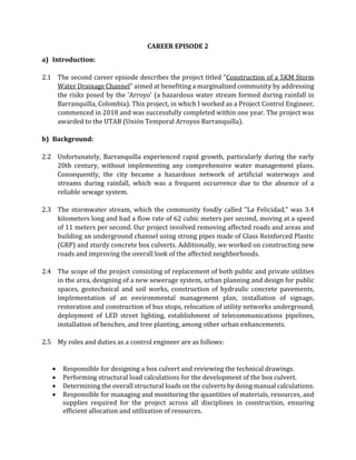
3. 2.8 I visited the project site, CALLE 48 and its surroundings, to assess the existing
stormwater drainage system and identify any potential issues or constraints. I
evaluated the topography, soil conditions, and nearby water bodies to understand the
site's hydrological characteristics. Based on the project requirements and site
assessment, I discussed the stormwater management design considering factors such
as rainfall intensity, catchment area, runoff volume, and water quality requirements,
including pipes and manholes.
Figure 1 District starts channeling work in Felicidad stream (elheraldo.co)
2.9 For the effective culvert design, I had to thoroughly study the engineering drawings and
specifications. These drawings depicted the plan, elevation, and cross-sections of the
box culvert, providing essential information about dimensions, reinforcement details,
and construction techniques. I reviewed these drawings to ensure proper alignment
with the project's design intent and coordinated with other disciplines to ensure
seamless integration with the overall stormwater drainage system. During this tenure,
I collaborated with hydraulic engineers, structural engineers, and drafters to address
any design challenges or modifications according to the City of Columbia Municipal
Code. By incorporating their expertise and feedback, I was able to refine the box culvert
design to optimize performance, efficiency, and cost-effectiveness. I also used software
(AutoCAD 3D) to develop the below aqueduct water of the new storm water system.
4. Figure 2 Aqueduct model
2.10 Meanwhile, I developed a detailed construction plan including sequencing of activities,
resource allocation, and construction methods by considering factors such as traffic
management, safety measures, and minimizing disruption to the surrounding areas. I
also identified and procured the required storm water management materials, such as
PEAD pipes, PVC pipes, manhole components, and other associated materials according
to the project specifications.
2.11 I analyzed the project requirements, including how much water needed to flow
through the culvert and the soil conditions. I proposed the hydraulic design of a single
box culvert by following a series of steps. Firstly, I calculated the headwater (H) using
a value of 1.95. By trial and error, I determined the culvert width (D) to be 1.2 m. Next,
I found that the headwater depth (J.+) was 1.04, which is less than the critical value (H`)
of 1.2. This indicated the need to calculate the required invert level. Next, I calculated
the required invert by subtracting the actual headwater (Hact) of 1.25 m from the
calculated headwater (Hcal) of 1.44 m, resulting in an invert value of 0.2 m. To verify
the invert level, I compared it to the critical value of 1.2. The calculation showed that
the invert level (H) was 1.4, which exceeded the critical value, confirming compliance
with the requirements.
5. 2.12 To determine the specific invert and top culvert levels, I subtracted the invert length
(0.2 m) from the main drain (MD-A) level of 7.31 m, yielding an invert level of 7.11 m.
Then, I added the culvert width (1.2 m) to the invert level, arriving at a top culvert level
of 8.31 m. Lastly, I checked the flow velocity (V) to ensure it fell within acceptable limits.
Using the Manning equation, I calculated the flow velocity to be 0.67 m/s. This value
indicated that the flow velocity was appropriate, as it was greater than 0.5 m/s to
prevent sedimentation and less than 1.5 m/s to prevent corrosion.
2.13 I performed the necessary load calculations. Due to the depth of fill being greater than
2400 mm and exceeding the distance between the faces of the end walls, the
distribution of wheel live load was neglected, as stated in the specifications, For the top
slab, I obtained the load factors from the design manual and I calculated the self-weight
load as 6 kN/m². Also, I determined the fill load to be 79.74 kN/m², resulting in a total
load of 115.15 kN/m².
2.14 To calculate the lateral earth pressure (EH) on the exterior side walls, I used Mohr's
equation to calculate the coefficient Ka. The coefficient was determined to be 1/3. With
a surcharge load of 18 kN/m², the constant horizontal earth pressure due to the
uniform surcharge was found to be 26.58 kN/m². Then, I calculated lateral earth
pressure on the side walls as 52.92 kN/m² (with surcharge) and 39.87 kN/m² (without
surcharge)
2.15 Thereafter, I prepared the project database using MS-Excel software showing
excavation tasks that were conducted on the project site. In the first excavation, I
manually calculated the excavation requirements for a 4" PVC pipe on the right side of
Calle 48, between abscissa points K0+402.00 and K0+402.00. The excavation had a
length of 7.32 meters, a width of 0.60 meters, and a height of 1.00 meter. Based on these
calculations, the total volume of material to be excavated was determined to be 7.32
cubic meters. This excavation was carried out to accommodate the installation of the 4"
PVC pipe, and the quantity of this item was 1.00.
2.16 I carried out two excavation tasks in different locations. The first excavation was done
on the left side of Calle 48, between the abscissa points K0+665.40 and K0+668.30. It
involved digging a hole for a 4" PVC pipe. The dimensions of this excavation were
determined to be 3.30 meters in length, 1.20 meters in width, and 1.50 meters in height.
I only needed to dig one hole of this size. Next, I performed an excavation for an 8" PVC
pipe on the right side of Calle 48, between the abscissa points K0+137.53 and
K0+131.53. This excavation was specifically done to accommodate the installation of
the 8" PVC pipe. The dimensions of this excavation were 6.00 meters in length, 0.60
meters in width, and 0.70 meters in height. Similarly, I only needed to dig one hole of
this size for the installation of the pipe.
6. 2.17 I also conducted a separate manual excavation on the right side of Calle 51, between
the abscissa points K1+227.10 and K1+267.70. This excavation was specifically done
for an 8" PVC pipe. The area that was excavated had dimensions of 40.60 meters in
length, 0.60 meters in width, and 1.18 meters in height. I only needed to dig one hole of
this size for the installation of the pipe.
2.18 In addition to the excavation tasks mentioned above, I was also involved in developing
the database of installation of two PEAD pipes on CALLE 48, TRANSVERSAL. The first
one was a 6" PEAD pipe, which I suggested installing at a station range starting at
K0+369.00. I selected this pipe for its Polyethylene High-Density material and a
diameter of 6 inches. It was installed to serve a particular purpose, such as drainage or
utility supply. A single section of this pipe was installed at the specified location.
Similarly, I suggested installing a 16" PEAD pipe at the same street, CALLE 48,
TRANSVERSAL, but with a different station range starting at K0+660.00. The larger
diameter of 16 inches indicates that this pipe is designed for a higher flow capacity or
larger-scale infrastructure. This pipe, too, was installed to serve a specific purpose such
as drainage or utility supply. One section of the 16" PEAD pipe was installed at the
specified location along CALLE 48, TRANSVERSAL
Figure 3 Database Complication of UTAB
2.19 Afterward, I used MS-Excel software to perform calculations and determine the
required quantities of materials for the supply and installation of a 39" diameter sewer
pipe made of Glass Reinforced Plastic (GRP). It was important to ensure that the
interior surface of the pipe was smooth, and the exterior had a profiled design. The
installation process also involved incorporating hydro seals and considering
transportation requirements. To calculate the quantities accurately, I specified the
7. locations for each element. For example, I mentioned the section called "FELICIDAD I
(MARGEN CRUCE)," which was the stretch between MH-23 and MH-23A on CALLE 48
ENTRE CRA 46 - CRA 45. Additionally, I provided abscissa values, which represent
positions along the road, to precisely identify the installation areas.
2.20 Next, I recorded the dimensions for each section. For example, in the "FELICIDAD I
(MARGEN CRUCE)" section, I selected a length of 12.94 meters, a width of 1.00 meter,
and no specified height. Similarly, I noted the dimensions for other sections like
"FELICIDAD I (MARGEN DERECHO)," which had a length of 66.40 meters, a width of
1.00 meter, and no specified height. Furthermore, I included the total quantities for
each section in the report. These quantities were calculated based on the provided
dimensions, with particular attention given to the length, width, and height of the areas
where the sewer pipe would be installed.
2.21 I compared the planned quantities with the actual quantities at the construction site,
which allowed me to monitor the progress efficiently and to ensure that everything was
being built according to the project requirements. If I noticed any differences, I worked
closely with the project team to address and resolve them.
2.22 After joining the project, I found out that the quantity amounts of all construction
progress were reported in site journals and paper-based documents. There was no
unified method of reporting, and there was a lack of clarity regarding the project's
progress. The company was undergoing a management change at that time, and new
policies were being implemented. Also, I found out that the information presented by
the site engineers to the PMO (Project Management Office) lacked veracity due to the
considerable amount of imprecisions found on the reports, compromising the
outcomes of the project because project engineers using a very old fashioned and
conservative managerial style.
2.23 As part of this change, I introduced the concept of creating a digital database. Then,
using this tool, I reviewed all the previous data, interpreting it, and uploading it in a
manner that anyone involved in the project could understand. Furthermore, from the
software, I organized the information and I started reporting it based on chainage.
Through this, I helped bring different areas of expertise together and showed that the
finished tasks between specific chainages included all the necessary work from each
discipline.
2.24 I ensured the implementation of traffic control in critical areas. Recognizing the impact
of dust on nearby residential areas, I took the initiative to install protective barriers and
arrange for an ongoing cleaning service to keep the construction areas as dust-free as
possible. I established temporary routes for traffic, managing access to houses, and
coordinating utilities, making necessary adjustments as the project progressed.
8. 2.25 I prioritized safety by scheduling the work during off-peak hours to minimize the
exposure of workers and the public to dangerous fumes. Additionally, as part of my role,
I enforced strict safety protocols for visitors to the site, emphasizing the importance of
wearing appropriate personal protective equipment (PPE) to ensure their safety.
d) Summary:
2.26 By applying my management skills, I was able introduced the Project management
techniques from the PMBOK which helped me to carry out proper planning, cost
controlling, and tracking the progress of the all disciplines. This technique was
approved by the client and I also used my engineering knowledge to use database excel
sheet properly suggesting the proper installation of the pipes and excavation work. The
new storm water plan was reviewed and approved by the higher authorizes which
reduced the problems in the city.