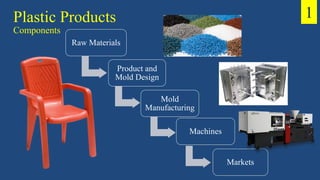
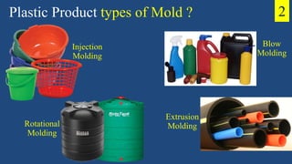
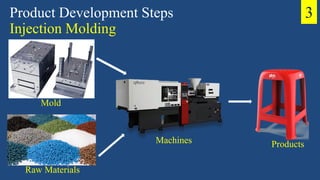
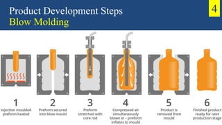
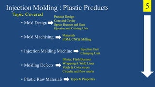
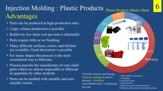
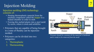
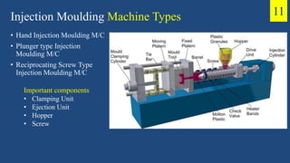
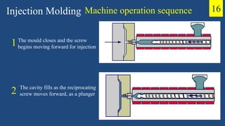
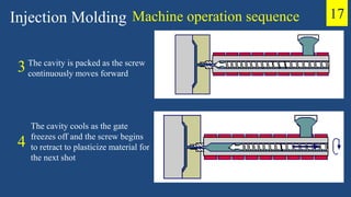
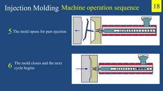
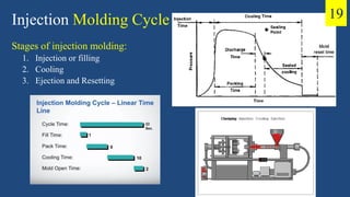
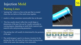
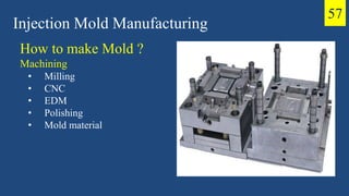
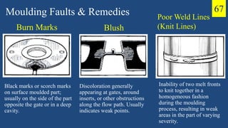
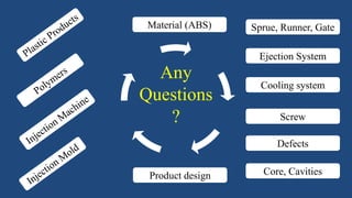
SlideShare a Scribd company logo
1 of 74
Download to read offline
Plastic!What comes in your mind?
.
.
.
.
.
Plastic
Good or Bad ? • Global Plastic Problems and Why is it ?
What are Single-use
Plastic ?
• Pet Bottles
• Wrappers
• Polyethene bags
50 %
Single –Use Waste
Plastic
Reuse
Recycle
Reduce
PLASTIC PRODUCTS
Kathmandu University, Nepal
Design and Production
Presentation on
Presented By:
Anamika Pokharel
Nirajan Ghimire
Injection Molding
Raw Materials
Product and
Mold Design
Mold
Manufacturing
Machines
Markets
Plastic Products
Components
1
Plastic Product types of Mold ?
Injection
Molding
Rotational
Molding
Blow
Molding
Extrusion
Molding
2
Product Development Steps
Injection Molding
Machines
Mold
Raw Materials
Products
3
Product Development Steps
Blow Molding
4
Injection Molding : Plastic Products
• Mold Design
• Mold Machining
• Injection Molding Machine
• Molding Defects
• Plastic Raw Materials
Injection Unit
Clamping Unit
Product Design
Core and Cavity
Sprue, Runner and Gate
Ejection and Cooling Unit
Topic Covered
Materials
EDM, CNC& Milling
Blister, Flash Burnout
Wrapping & Weld Lines
Voids & Color stress
Circular and flow marks
Types & Properties
5
6
13%
47%
14%
8%
11%
7%
Plastic Products Market Share
White goods, construction
Packaging
Auomotive parts
technical parts
Electronics and telecommunicaions
Medical, pharmacuitical and optical product
In North America and Europe,
Injection molding is used to
process > 10million
tons(10billion KG ) of polymers
per year
Packaging
Injection Molding : Plastic Products
Advantages
• Parts can be produced at high production rates
• Large volume production is possible
• Relatively low labor cost per unit is obtainable
• Parts require little or no finishing
• Many different surfaces, colors, and finishes
are available, Good decoration is possible
• For many shapes this process is the most
economical way to fabricate
• Process permits the manufacture of very small
parts which are almost impossible to fabricate
in quantities by other methods
• Parts can be molded with metallic and non-
metallic inserts
Injection Molding
Pressure should be constant till the material is hardened
and is ready to be removed from the mold
7
Injection molding (IM) technology
consists of:
• Heating thermoplastic material from the
machine component called the hopper to a
heated chamber in order to melt
• Forcing this melted plastic into a steel mold
by screw, where it cools and solidifies
• Polymers that are capable of being brought
to a state of fluidity can be injection-
molded.
• Polymers can be divided into two
categories:
1. Thermoplastic
2. Thermosetting
Injection Molding Raw Materials
• ABS
• HDPE
• Polypropylene(PP)
• LDPE
• Polyethylene (PE)
• Polycarbonate
• Polyamide (Nylon)
8
Injection Molding Raw Materials
Heat deflection temperature:
• Temperature at which a thermoplastic
can be operated under load
• This is the temperature at which a
simply supported beam specimen of the
material, with a centrally applied load,
reaches a predefined deflection
Raw materials :
PP + LDPE (color) +
Master batch (strength)
9
Injection Molding Raw Materials 10
Additive Function Examples
Filler increase bulk density calcium carbonate, talc,
limestone
Plasticizer improve processability, reduce
product brittleness
phthalate esters,
phosphate esters
Antioxidant prevent polymer oxidation phenols, aromatic
amines
Colorant provide desired part application
color
oil-soluble dyes, organic
pigments
Flame retardant reduce polymer flammability antimony trioxide
Stabilizer stabilize polymer against heat or
UV light
carbon black,
hydroxybenzophenone
Reinforcement improve strength E-glass, S-glass, carbon,
Kevlar fibers
Injection Moulding Machine Types
• Hand Injection Moulding M/C
• Plunger type Injection
Moulding M/C
• Reciprocating Screw Type
Injection Moulding M/C
11
Important components
• Clamping Unit
• Ejection Unit
• Hopper
• Screw
Injection Molding Machine
Clamping
Unit
Mold
Control
System
Output
Product
Hopper
Screw
Ejection
System
12
Injection Molding Machine Size
• Injection units are usually rated with two
numbers:
1. First rating No.: Shot capacity
2. Second rating number: plasticizing rate
• Shot capacity: max volume of polymer
that can be displaced by one forward
stroke of injection plunger or screw.
• recommended shot sizes: 20 to 80% of
rated capacity.
Plasticizing rate: amount of material that can be softened into a molten
form by heating in the cylinder of machine in a given time.
• It is usually expressed as No. of pounds of polystyrene material that
the equipment can heat to molding temperature in one hour
13
Reciprocating Screw
• The feeding zone
• The compressing (or
transition) zone
• The metering zone
Injection Molding Machine 14
Injection
• Plasticizes the material by reciprocating
Screw
• Injects the molten material to a closed
mold via a channel system of gates and
runners.
• Cools the Mold
• Refills the material for the next cycle
• Ejects the Product
• Closes the Mold for further cycle
Injection Molding Process 15
How plastic product
were developed?
How Injection Molding
Process Works?
Machine operation sequence
The mould closes and the screw
begins moving forward for injection
The cavity fills as the reciprocating
screw moves forward, as a plunger
Injection Molding
1
2
16
Machine operation sequence
The cavity is packed as the screw
continuously moves forward
The cavity cools as the gate
freezes off and the screw begins
to retract to plasticize material for
the next shot
Injection Molding
3
4
17
Machine operation sequence
The mold opens for part ejection
The mold closes and the next
cycle begins
Injection Molding
5
6
18
Injection Molding Cycle
Stages of injection molding:
1. Injection or filling
2. Cooling
3. Ejection and Resetting
19
Injection or Filling Stage
• Forward stroke of plunger to facilitate flow of molten material from the heating
cylinder through nozzle and into mold.
• Gradual increase in pressure.
• As soon as cavity is filled, pressure increases rapidly, and packing occurs.
• During packing part, flow of material continues, at a slower rate, to account for
any loss in volume of material due to partial solidification and shrinkage.
• After packing, injection plunger is withdrawn and pressure in mold cavity begins
to drop.
• At this stage, next charge of material is fed into the heating cylinder in preparation
for next shot.
Injection Molding Cycle 20
Cooling Stage
• Cooling starts from 1st rapid filling of cavity and continues during packing and then following
withdrawal of the plunger, with the resulting removal of pressure from the mold and nozzle area.
• Upon pressure removal, gate of mold may still be relatively fluid.
• Because of pressure drop, there is a chance for reverse flow of material from mold until material
adjacent to the gate solidifies and the sealing point is reached.
• Reverse flow is minimized by proper design of gates such that quicker sealing action takes place
upon plunger withdrawal.
• Following the sealing point, there is a continuous drop in pressure as material in cavity continues to
cool and solidifies in readiness for ejection.
• Length of sealed cooling stage depends on:
1.wall thickness of part
2.material used
3.mold temperature
• Because of low thermal conductivity of polymers, cooling time is usually the longest period in the
molding cycle.
Injection Molding Cycle 21
Ejection and Resetting Stage
• During this stage:
1.mold is opened
2.part is ejected,
3.mold is then closed again in readiness for next cycle to begin.
• Rapid movements may cause:
1.undue strain on the equipment
2.damage the edges of the cavities
• Adequate time must be allowed for mold ejection.
• This time depends on part dimensions
• For parts to be molded with metal inserts, resetting involves reloading of inserts
into mold. After resetting, mold is closed and locked, thus completing one cycle.
Injection Molding Cycle 22
• Clamp unit has three functions:
1. open and close mold halves
2. eject the part
3. hold mold closed with sufficient force to resist melt pressure inside mold as it
is filled
• Required holding force: 30 to70 MN/m2 of projected area of part
• Magnitude of initial opening force required depends on:
1. packing pressure
2. Material
3. part geometry (depth and draft)
• is approximately equal to 10 to 20% of nominal clamp force.
Injection Molding Machine
Clamp Unit
23
Injection Molding Machine
Clamp Unit
Two common types of clamp designs:
1. Linkage or toggle clamp:
• very fast closing and opening actions
• lower in cost than alternative systems
• clamp force is not precisely controlled
2. Hydraulic clamp units:
• long term reliability
• precise control of clamp force
• relatively slow and expensive compared to toggle
clamp systems.
• Force required to eject the part depends on:
1. Material
2. part geometry
3. packing pressure
• less than 1% of nominal clamp force
24
Calm down
We are half way out
Injection Mold
25
Dr. Mohammad Abuhaiba
Injection Mold
1. Fixed Clamping Plate
2. Runner Stripper Plate
3. Cavity plate
4. Movable Cavity Plate or
Cavity plate
5. Back up Plate
6. Spacer Block
7. Ejector retainer plate
8. Ejector Plate
9. Movable Clamping Plate
Components
26
• Mold basically consists of two parts:
1. a stationary half (cavity plate)
2. a moving half (core plate)
• Parting line: separating line between the
two mold halves
• The injected material is transferred
through a central feed channel, called the
sprue.
• In multi-cavity molds, sprue feeds
polymer melt to a runner system.
Injection Mold
Most common Types of molds:
1. Two-plate molds
2. Three-plate molds
3. Side-action molds
4. Unscrewing molds
27
• Core plate holds the main core.
• Purpose of main core is to establish the inside configuration of
the part.
• The core plate has a backup plate.
• Backup plate in turn is supported by pillars against the U
shaped structure known as the ejector housing, which consists
of the rear clamping plate and spacer blocks.
• The U-shaped structure, which is bolted to core plate, provides
the space for the ejection stroke.
Injection Mold Design 28
Injection Mold Design
Cavity ? Core ?
Injection Mold is an assembly of parts
containing within it an impression into
which plastic material is injected and
cooled
Impression is defined as the part of mold
which imparts shape to the molding
Impression consist of:
• Cavity
• Core
Cavity: Hollow portion of the Mold, gives
the molding its external form
Core: Projected portion of Mold, forms
the internal shape of molding
Cavity
Core
29
Injection Mold Design Cavity ? Core ?
Simple Concept: Mold
Cavity
Core
Cavity Core
30
Injection Mold Design
Core Plate and
Cavity Plate
Core Plate: Plate or assembly
which contains the core
Cavity Plate: Plate or assembly
which contains the cavity
31
Injection Mold Sprue 32
Injection Mold Sprue
33
Sprue Bush
During the injection process, plastic materials is
delivered to the nozzle of the machine as a
melt; it is then transferred to the impression
through passage
This passage is tapered hole within a bush. The
material in this passage is termed as sprue and
the bush is called sprue bush
Feed System for single impression mold
34
Sprue Bush
• Is a connection member between the machine nozzle
and the mold face, and provides a suitable aperture
through which the material can travel on its way to
the impression or to the start of the runner system.
• Sprue bushes are made from 1.5% Nickel Chrome
steel and should always be hardened.
• The internal aperture of the sprue bush has between 2
to 4° included taper, which facilitates the removal of
the sprue from the mold at the end of the molding
cycle
Spherical seating
Flat seatingTypes of Sprue Bush
• Spherical seating
• Flat seating
35
Sprue Design 36
Injection Mold Design
Runner and Gate
• Runner is a channel machined into the mold
plate to connect the sprue with the gate to the
impression
• Gate is a channel or orifice connecting the
runner with the impression
• Feed system is a flow way which connect the
nozzle of the injection molding to each
impression
Feed system for multi impression mold
37
Unbalance Sprue Material Design 38
Unbalance Sprue Material Design 39
Balance Sprue Material Design
40
Balance Sprue Material Design 41
Types of Gate
42
• Sprue gate – this gate is suitable for single
chamber parts and thick sections because it can
hold pressure well. The disadvantage of this gate
is that a mark is left on top.
• Pin gate – for parts that have multiple cavities or
chambers. It is usually located at the top.
• Tunnel gates – also known as submarine gates, it can
be placed at the side or movable parts of the mold. It
is automatically cut as the mold opens.
Types of Gate
43
• Sub gate is used for 2 plates molds, the gate point is very
small and location of the gate is choose to be on uncritical
area, the gate can be easily trimmed off along with the action
of injection mold opening, this type of gate is widely
employed for automatically plastic products production.
• Fan gate – commonly used for large or flat
plate parts. It is placed at the sides and
manually cut by a cutter.
• Direct gate. Commonly used for single cavity molds, it
required less injection pressure and feeding time is short,
but the disadvantage of this type gate is difficult to remove
and there would be big gate marks left. This gate type is
common to see in house appliance and consumer product,
such as bins, printers, washing machine, TV etc.
Injection Mold Cooling
One fundamental principle of Injection Molding is
that hot material enters the mold, where it cools
rapidly to a temperature at which it solidifies
sufficiently to retain the shape of the impression
Factors deciding operating temperature of mold:
• Type and grade of material to be molded
• Length of within the impression
• Wall section of the molding
• Length of the feed system. Etc.
It is often found advantageous
to use a slightly higher
temperature than is required
just to fill the impression, as
this tends to improve the
surface finish of the molding
by minimizing weld lines, flow
marks and other blemishes
44
Injection Mold Cooling
• To maintain the required temperature differential
between the mold and plastic material, water or
other fluid is circulated through holes or
channels within the mold.
• The holes or channels are termed flow ways or
water ways and
• The complete system of flow ways is termed the
circuit or cooling circuit
Cooling Circuit
45
Injection Mold Cooling
Cooling Integer type mold plates
• Cooling Integer type cavity plate
• Cooling Integer type core plate
Cooling Insert – Bolster Assembly
• Cooling Bolster
• Cooling Insert
o Cooling Cavity Inserts
o Cooling Core Inserts
Cooling Circuit Classifications Different types of cooling Integer type cavity
plate are;
1. Simple circuit
2. U-Circuit
3. U-Circuit with interconnecting milled
channel
4. U-Circuit with interconnecting milled
channel
5. Rectangular circuit
6. Z – Circuit
46
Injection Mold Cooling
1. Simple Circuit 2. Rectangular Circuit
47
Injection Mold Cooling
3. U-circuit with interconnection milled
channel 4. Z-Circuit
48
Injection Mold Cooling
5. Angle hole System 6. Baffled straight hole system
49
Injection Mold Ejection System 50
• Pin Ejection
o Cylindrical pins are used for ejection purpose, in case of square and
rectangular components minimum fore pins
o a the four corners are required and in case of cylindrical component
minimum
o three pins at 120° apart is required based on the component profile,
size and area of ejection the number of pins to be increased.
o visible ejection marks will be there on component
•
• Sleeve Ejection
o This type of ejection is preferred for only to cylindrical cores and core
has to be fixed in bottom plate.
o ejection is limited to cylindrical core due to manufacturing constrains,
when ejection assembly is moved the sleeve will slide over the core
and eject the component.
o No visible ejection marks will be there on component
Injection Mold Ejection System 51
• Stripper Plate ejection
o This ejection is preferred for component with larger area, an
additional plate (stripper) will be provided in between core plate
and cavity plate.
o In order to avoid flash the stripper plate will be in contact with
cavity plate and gap is maintained between cavity and core plate.
o No visible ejection marks will be there on component
• Air Ejection
o This method is used to actuating the ejection pin fitted in
core using compressed air.
o Retraction of ejection pin in core is by spring.
Injection Mold Ejection System 52
Blade Ejection
o This type of ejection is preferred for thin rectangular cross
sections
o rectangular blades will inserted in cylindrical
pins or cylindrical pins will be machined to rectangular
cross section till ejection length
o for easy accommodation of ejection pin head in counter
bore provided in ejection plates
By Rotation of Core (Internal Threaded Components)
o This method of ejection is required for threaded
components
o component is automatically ejected by rotating the
core insert
Calm down
Almost Done!
Mold Types – three-plate mold
• Consists of:
1. Stationary or runner plate, which
contains sprue and half of runner
2. Middle or cavity plate, which contains
other half of runner, gates, and cavities
and is allowed to float when mold is
open
3. Movable or core plate, which contains
cores and ejector system.
• Facilitates separation of runner system and
part when mold opens
Injection Mold 53
• Three main plates
• Runner is contained completely in the fixed plate,
which is heated and insulated from the rest of the
cooled mold.
• Runner section of the mold is not opened during
molding cycle.
• There are no side products (gates, runner, or sprues)
to be disposed of or reused
• There is no need for separation of gate from part
Injection Mold
Mold Types – Hot runner system
54
• Used in molding components with external
depressions or holes parallel to the parting plane.
• Undercuts prevent molded parts from being
removed from cavity in axial direction.
• The usual way of providing the side action
needed to release the part is with side cores
mounted on slides.
• These are activated by angle pins, or by air or
hydraulic cylinders that pull the side cores
outward during opening of the mold.
• As the two halves of the mold move apart during
mold opening, the slide, which is mounted on the
moving plate, is forced to move sideways by the
angle of the pin.
Injection Mold
Mold Types – Side-acting Molds
55
Injection Mold
Parting Lines
56
• “parting line” refers to a line on the part that is created
where the two halves of the mold come together.
• results is a faint, sometimes unnoticeable line on the part.
• This line usually doesn’t affect the overall shape or
dimensions of the part, but can be visually noticeable to
varying degrees, depending on mold finish, material type,
material color and processing parameters.
• The parting line will usually be determined by the geometry
of the part.
• The mold designer’s goal is to choose a location for the
parting line that will create the most robust tooling design,
while at the same time making it less noticeable.
Injection Mold Manufacturing
How to make Mold ?
Machining
• Milling
• CNC
• EDM
• Polishing
• Mold material
57
Injection Mold Manufacturing
Selection Criteria Selection Criteria
• Type of Mold Type of Mold
• Mold life i.e. Number of accepted Mold life
• i.e. Number of accepted components produced over its
components produced over its working life working life
• Ability to take mirror finish (High Ability to take mirror finish (High
degree of polishibility) degree of polishibility)
• Good machinability
• Good hardenability Good hardenability
• Low distortion during Heat Low distortion during Heat treatment
treatment
• Corrosion resistant Corrosion resistant
• High compressive strength High compressive strength
• High toughness
59
Injection Mold Manufacturing
Mould Design Requirements Role and responsibility of
a Mould Designer
• Ensures that the mould is fabricated as easily and as
economical as possible by the mould maker
• Specifies best mould steels with optimum hardness required for
different optimum mould parts
• Selection of standard parts such as such as guide pillars, Guide
bushes, ejector pins etc, standard mould bases reduces time and
cost
• Helps in better planning, prompt mould delivery as well as
minimizing initial machining cost and material losses
60
Injection Mold Manufacturing
Some of the commonly used
steels are:
• Pre hardened Mould Steels
• Through hardened mould steels
• Corrosion resistant mould steels
• Plain carbon Steels
61
Carbon Steel Carbon Content
Low Carbon Steel 0.1 – 0.3 % 0.1 – 0.3 %
Medium Carbon Steel 0.3 – 0.7 % 0.3 – 0.7 %
High Carbon Steel 0.6 – 1.5 %
ALLOY STEELS
More stronger, tougher and resistant than carbon steel
Sufficient formability, ductility and weld ability
Corrosion and abrasion resistant
Typical application are
Structural applications
• HIGH CARBON HIGH CHROMIUM STEEL
• STAINLESS STEEL
Injection Mold Manufacturing
Machining/ Milling / CNC / EDM
62
Moulding Faults & Remedies
• Sink
• Jetting
• Splay Marks (Silver Streaking, Splash Marks)
• Burn Marks
• Blush
• Poor Weld Lines (Knit Lines)
• Short shot
• Flash
• Cracking
• Blister
• Brittleness
• Black specks
• Warpage
63
Sink Marks
Depression in a moulded part caused by shrinking or
collapsing of the resin during cooling.
Moulding Faults & Remedies
Resin feed inadequate
Improper mould design.
Parts cool too rapidly
Rib section in part too wide.
Temperature of mould surface opposite rib too hot.
Entrapped gas.
Nozzle too restrictive,
land length too long.
Sink Marks Problems • Pressure too low.
• Mould temperature too low or high
• Stock temperature too high
• Gate too small
• Improper gate location
• Nozzle and metering zone temperatures too high.
• Excessive cooling time in mould
• Unbalanced flow pattern.
• Bad check valve.
64
Jetting
Turbulence in the resin melt flow caused by undersized
gate, abrupt change in cavity volume, or too high
injection pressure.
Moulding Faults & Remedies
Jetting Problems
• Excessive injection speed.
• Melt temperature too high.
• Melt temperature too low.
• mould Temperature too low.
• Nozzle opening too small.
• Gate and length too long.
• Sprue, runner, and/or gate size too small.
• Nozzle heating band malfunction.
• Inefficient gate location.
65
Splay Marks (Silver Streaking, Splash
Marks)
• Marks or droplet type imperfections formed on the
surface of a finished part.
Moulding Faults & Remedies
• Obstruction in nozzle.
• Screw rpm too high.
• Back pressure too low.
• Melt temperature too high.
• Nozzle too hot.
• Nozzle too small.
• Gates too small.
• Sprue too small.
• Insufficient venting.
Problems • Burr in runner or gate.
• Cracked mould.
• Trapped volatiles.
• Excessive moisture.
• Resin contaminated.
• mould cavity contamination.
• Excessive shot size.
66
Burn Marks
Black marks or scorch marks
on surface moulded part;
usually on the side of the part
opposite the gate or in a deep
cavity.
Moulding Faults & Remedies
Blush
Discoloration generally
appearing at gates, around
inserts, or other obstructions
along the flow path. Usually
indicates weak points.
Poor Weld Lines
(Knit Lines)
Inability of two melt fronts
to knit together in a
homogeneous fashion
during the moulding
process, resulting in weak
areas in the part of varying
severity.
67
Plastic Products Markets
Injection molding products: 19.3%
68
Plastic Raw materials tax: 10%
Machine tax: 15%
Plastic product tax: 56%
No. of Plastic industries in Nepal: 250+
Major product: PVC pipe, PET bottles,
Household utensils, polyethene bag,
hardware accessories
Make your Plastic product and Sell
Thank You!
You are amazing listeners
Any
Questions
?
.
.
.
.
.
Sprue, Runner, Gate
Ejection System
Cooling system
Screw
Defects
Core, CavitiesProduct design
Material (ABS)

More Related Content

What's hot

Plastic injection moulding ppt
Plastic injection moulding pptPlastic injection moulding ppt
Plastic injection moulding pptMayuresh Patil
 
Injection moulding ppt
Injection moulding pptInjection moulding ppt
Injection moulding pptdobhal001
 
Types of mould
Types of mould Types of mould
Types of mould Veer Singh
 
Plastics
PlasticsPlastics
Plasticscpandiv
 
Engineering Guidelines to Designing Plastic Parts for Injection Molding
Engineering Guidelines to Designing Plastic Parts for Injection MoldingEngineering Guidelines to Designing Plastic Parts for Injection Molding
Engineering Guidelines to Designing Plastic Parts for Injection MoldingJaycon Systems
 
presentation on mould
presentation on mouldpresentation on mould
presentation on mouldBADAL PANCHAL
 
Seminar on all electrical injection moulding machine main
Seminar on all electrical injection moulding machine mainSeminar on all electrical injection moulding machine main
Seminar on all electrical injection moulding machine mainanymona1991
 
3. Blow moulding process
3.  Blow moulding process3.  Blow moulding process
3. Blow moulding processVeer Singh
 
Compression moulding
Compression mouldingCompression moulding
Compression mouldingAdarsh Singh
 
Injection moulding modified
Injection moulding modifiedInjection moulding modified
Injection moulding modifiedSuman Ku. Sharma
 
Plastic manufacturing "forming and shaping plastics"
Plastic manufacturing "forming and shaping plastics"Plastic manufacturing "forming and shaping plastics"
Plastic manufacturing "forming and shaping plastics"Ayush Mathur
 

What's hot (20)

Advances in im
Advances in imAdvances in im
Advances in im
 
Extrusion molding
Extrusion moldingExtrusion molding
Extrusion molding
 
Plastic injection moulding ppt
Plastic injection moulding pptPlastic injection moulding ppt
Plastic injection moulding ppt
 
Plastic processing
Plastic processingPlastic processing
Plastic processing
 
Injection moulding ppt
Injection moulding pptInjection moulding ppt
Injection moulding ppt
 
Types of mould
Types of mould Types of mould
Types of mould
 
Plastics
PlasticsPlastics
Plastics
 
Transfer moulding
Transfer mouldingTransfer moulding
Transfer moulding
 
Polymer extrusion
Polymer extrusionPolymer extrusion
Polymer extrusion
 
Blow molding
Blow moldingBlow molding
Blow molding
 
Engineering Guidelines to Designing Plastic Parts for Injection Molding
Engineering Guidelines to Designing Plastic Parts for Injection MoldingEngineering Guidelines to Designing Plastic Parts for Injection Molding
Engineering Guidelines to Designing Plastic Parts for Injection Molding
 
presentation on mould
presentation on mouldpresentation on mould
presentation on mould
 
Seminar on all electrical injection moulding machine main
Seminar on all electrical injection moulding machine mainSeminar on all electrical injection moulding machine main
Seminar on all electrical injection moulding machine main
 
3. Blow moulding process
3.  Blow moulding process3.  Blow moulding process
3. Blow moulding process
 
Compression moulding
Compression mouldingCompression moulding
Compression moulding
 
Processing polymer
Processing polymerProcessing polymer
Processing polymer
 
Injection moulding modified
Injection moulding modifiedInjection moulding modified
Injection moulding modified
 
Plastic manufacturing "forming and shaping plastics"
Plastic manufacturing "forming and shaping plastics"Plastic manufacturing "forming and shaping plastics"
Plastic manufacturing "forming and shaping plastics"
 
extrusion processing
extrusion processingextrusion processing
extrusion processing
 
Blow molding Process
Blow molding ProcessBlow molding Process
Blow molding Process
 

Similar to Plastic Products: Types, Development Process and Market Share

Ijection Molding
Ijection MoldingIjection Molding
Ijection MoldingFahad jee
 
Ideal process parameters in injection moulding
Ideal process parameters in injection  mouldingIdeal process parameters in injection  moulding
Ideal process parameters in injection mouldingNaik Devang
 
Blow & Injection Molding Process....pptx
Blow & Injection Molding Process....pptxBlow & Injection Molding Process....pptx
Blow & Injection Molding Process....pptxecengineering
 
INJECTION MOLDING PROCESS
INJECTION MOLDING PROCESSINJECTION MOLDING PROCESS
INJECTION MOLDING PROCESSNauman Asif
 
Industrial training (1).pptx
Industrial training (1).pptxIndustrial training (1).pptx
Industrial training (1).pptxmohanbabuy909
 
Injection Moulding_TY(1)(1)(1).pdf
Injection Moulding_TY(1)(1)(1).pdfInjection Moulding_TY(1)(1)(1).pdf
Injection Moulding_TY(1)(1)(1).pdfBramhanandUkey
 
Polymer_Processing.ppt
Polymer_Processing.pptPolymer_Processing.ppt
Polymer_Processing.pptHAriesOa1
 
Lec 30-33_Polymer Processing.pdf
Lec 30-33_Polymer Processing.pdfLec 30-33_Polymer Processing.pdf
Lec 30-33_Polymer Processing.pdfNTU Faisalabad
 
Plastic moulding
Plastic mouldingPlastic moulding
Plastic mouldingKonal Singh
 
Compression Molding Presentation
Compression Molding PresentationCompression Molding Presentation
Compression Molding PresentationFirdhaus Sakaff
 
Injection and Blow Molding
Injection and Blow MoldingInjection and Blow Molding
Injection and Blow Moldingfaheem maqsood
 
PLASTIC MOULDING and Methods involving in it
PLASTIC MOULDING and Methods involving in itPLASTIC MOULDING and Methods involving in it
PLASTIC MOULDING and Methods involving in itGaurav Tyagi
 
Extrusion blow molding
Extrusion blow moldingExtrusion blow molding
Extrusion blow moldingFahad jee
 

Similar to Plastic Products: Types, Development Process and Market Share (20)

Ijection Molding
Ijection MoldingIjection Molding
Ijection Molding
 
Pro E/Mold Design (Pro/MOLDESIGN)
Pro E/Mold Design (Pro/MOLDESIGN)Pro E/Mold Design (Pro/MOLDESIGN)
Pro E/Mold Design (Pro/MOLDESIGN)
 
Ideal process parameters in injection moulding
Ideal process parameters in injection  mouldingIdeal process parameters in injection  moulding
Ideal process parameters in injection moulding
 
Blow & Injection Molding Process....pptx
Blow & Injection Molding Process....pptxBlow & Injection Molding Process....pptx
Blow & Injection Molding Process....pptx
 
Aadrsh kumar tiwari bbau
Aadrsh kumar tiwari bbauAadrsh kumar tiwari bbau
Aadrsh kumar tiwari bbau
 
INJECTION MOLDING PROCESS
INJECTION MOLDING PROCESSINJECTION MOLDING PROCESS
INJECTION MOLDING PROCESS
 
Industrial training (1).pptx
Industrial training (1).pptxIndustrial training (1).pptx
Industrial training (1).pptx
 
Injection Moulding_TY(1)(1)(1).pdf
Injection Moulding_TY(1)(1)(1).pdfInjection Moulding_TY(1)(1)(1).pdf
Injection Moulding_TY(1)(1)(1).pdf
 
Blow molding
Blow moldingBlow molding
Blow molding
 
Polymer_Processing.ppt
Polymer_Processing.pptPolymer_Processing.ppt
Polymer_Processing.ppt
 
Injection moulding
Injection mouldingInjection moulding
Injection moulding
 
Injection molding
Injection moldingInjection molding
Injection molding
 
Lec 30-33_Polymer Processing.pdf
Lec 30-33_Polymer Processing.pdfLec 30-33_Polymer Processing.pdf
Lec 30-33_Polymer Processing.pdf
 
Plastic moulding
Plastic mouldingPlastic moulding
Plastic moulding
 
Lec 2
Lec 2Lec 2
Lec 2
 
Injection moulding
Injection mouldingInjection moulding
Injection moulding
 
Compression Molding Presentation
Compression Molding PresentationCompression Molding Presentation
Compression Molding Presentation
 
Injection and Blow Molding
Injection and Blow MoldingInjection and Blow Molding
Injection and Blow Molding
 
PLASTIC MOULDING and Methods involving in it
PLASTIC MOULDING and Methods involving in itPLASTIC MOULDING and Methods involving in it
PLASTIC MOULDING and Methods involving in it
 
Extrusion blow molding
Extrusion blow moldingExtrusion blow molding
Extrusion blow molding
 

Recently uploaded

What are the advantages and disadvantages of membrane structures.pptx
What are the advantages and disadvantages of membrane structures.pptxWhat are the advantages and disadvantages of membrane structures.pptx
What are the advantages and disadvantages of membrane structures.pptxwendy cai
 
GDSC ASEB Gen AI study jams presentation
GDSC ASEB Gen AI study jams presentationGDSC ASEB Gen AI study jams presentation
GDSC ASEB Gen AI study jams presentationGDSCAESB
 
Biology for Computer Engineers Course Handout.pptx
Biology for Computer Engineers Course Handout.pptxBiology for Computer Engineers Course Handout.pptx
Biology for Computer Engineers Course Handout.pptxDeepakSakkari2
 
Gurgaon ✡️9711147426✨Call In girls Gurgaon Sector 51 escort service
Gurgaon ✡️9711147426✨Call In girls Gurgaon Sector 51 escort serviceGurgaon ✡️9711147426✨Call In girls Gurgaon Sector 51 escort service
Gurgaon ✡️9711147426✨Call In girls Gurgaon Sector 51 escort servicejennyeacort
 
INFLUENCE OF NANOSILICA ON THE PROPERTIES OF CONCRETE
INFLUENCE OF NANOSILICA ON THE PROPERTIES OF CONCRETEINFLUENCE OF NANOSILICA ON THE PROPERTIES OF CONCRETE
INFLUENCE OF NANOSILICA ON THE PROPERTIES OF CONCRETEroselinkalist12
 
Sachpazis Costas: Geotechnical Engineering: A student's Perspective Introduction
Sachpazis Costas: Geotechnical Engineering: A student's Perspective IntroductionSachpazis Costas: Geotechnical Engineering: A student's Perspective Introduction
Sachpazis Costas: Geotechnical Engineering: A student's Perspective IntroductionDr.Costas Sachpazis
 
Electronically Controlled suspensions system .pdf
Electronically Controlled suspensions system .pdfElectronically Controlled suspensions system .pdf
Electronically Controlled suspensions system .pdfme23b1001
 
Concrete Mix Design - IS 10262-2019 - .pptx
Concrete Mix Design - IS 10262-2019 - .pptxConcrete Mix Design - IS 10262-2019 - .pptx
Concrete Mix Design - IS 10262-2019 - .pptxKartikeyaDwivedi3
 
Call Girls Delhi {Jodhpur} 9711199012 high profile service
Call Girls Delhi {Jodhpur} 9711199012 high profile serviceCall Girls Delhi {Jodhpur} 9711199012 high profile service
Call Girls Delhi {Jodhpur} 9711199012 high profile servicerehmti665
 
Software and Systems Engineering Standards: Verification and Validation of Sy...
Software and Systems Engineering Standards: Verification and Validation of Sy...Software and Systems Engineering Standards: Verification and Validation of Sy...
Software and Systems Engineering Standards: Verification and Validation of Sy...VICTOR MAESTRE RAMIREZ
 
Gfe Mayur Vihar Call Girls Service WhatsApp -> 9999965857 Available 24x7 ^ De...
Gfe Mayur Vihar Call Girls Service WhatsApp -> 9999965857 Available 24x7 ^ De...Gfe Mayur Vihar Call Girls Service WhatsApp -> 9999965857 Available 24x7 ^ De...
Gfe Mayur Vihar Call Girls Service WhatsApp -> 9999965857 Available 24x7 ^ De...srsj9000
 
APPLICATIONS-AC/DC DRIVES-OPERATING CHARACTERISTICS
APPLICATIONS-AC/DC DRIVES-OPERATING CHARACTERISTICSAPPLICATIONS-AC/DC DRIVES-OPERATING CHARACTERISTICS
APPLICATIONS-AC/DC DRIVES-OPERATING CHARACTERISTICSKurinjimalarL3
 
OSVC_Meta-Data based Simulation Automation to overcome Verification Challenge...
OSVC_Meta-Data based Simulation Automation to overcome Verification Challenge...OSVC_Meta-Data based Simulation Automation to overcome Verification Challenge...
OSVC_Meta-Data based Simulation Automation to overcome Verification Challenge...Soham Mondal
 
HARMONY IN THE NATURE AND EXISTENCE - Unit-IV
HARMONY IN THE NATURE AND EXISTENCE - Unit-IVHARMONY IN THE NATURE AND EXISTENCE - Unit-IV
HARMONY IN THE NATURE AND EXISTENCE - Unit-IVRajaP95
 
Microscopic Analysis of Ceramic Materials.pptx
Microscopic Analysis of Ceramic Materials.pptxMicroscopic Analysis of Ceramic Materials.pptx
Microscopic Analysis of Ceramic Materials.pptxpurnimasatapathy1234
 
Decoding Kotlin - Your guide to solving the mysterious in Kotlin.pptx
Decoding Kotlin - Your guide to solving the mysterious in Kotlin.pptxDecoding Kotlin - Your guide to solving the mysterious in Kotlin.pptx
Decoding Kotlin - Your guide to solving the mysterious in Kotlin.pptxJoão Esperancinha
 
Introduction-To-Agricultural-Surveillance-Rover.pptx
Introduction-To-Agricultural-Surveillance-Rover.pptxIntroduction-To-Agricultural-Surveillance-Rover.pptx
Introduction-To-Agricultural-Surveillance-Rover.pptxk795866
 

Recently uploaded (20)

What are the advantages and disadvantages of membrane structures.pptx
What are the advantages and disadvantages of membrane structures.pptxWhat are the advantages and disadvantages of membrane structures.pptx
What are the advantages and disadvantages of membrane structures.pptx
 
GDSC ASEB Gen AI study jams presentation
GDSC ASEB Gen AI study jams presentationGDSC ASEB Gen AI study jams presentation
GDSC ASEB Gen AI study jams presentation
 
Biology for Computer Engineers Course Handout.pptx
Biology for Computer Engineers Course Handout.pptxBiology for Computer Engineers Course Handout.pptx
Biology for Computer Engineers Course Handout.pptx
 
Gurgaon ✡️9711147426✨Call In girls Gurgaon Sector 51 escort service
Gurgaon ✡️9711147426✨Call In girls Gurgaon Sector 51 escort serviceGurgaon ✡️9711147426✨Call In girls Gurgaon Sector 51 escort service
Gurgaon ✡️9711147426✨Call In girls Gurgaon Sector 51 escort service
 
INFLUENCE OF NANOSILICA ON THE PROPERTIES OF CONCRETE
INFLUENCE OF NANOSILICA ON THE PROPERTIES OF CONCRETEINFLUENCE OF NANOSILICA ON THE PROPERTIES OF CONCRETE
INFLUENCE OF NANOSILICA ON THE PROPERTIES OF CONCRETE
 
Sachpazis Costas: Geotechnical Engineering: A student's Perspective Introduction
Sachpazis Costas: Geotechnical Engineering: A student's Perspective IntroductionSachpazis Costas: Geotechnical Engineering: A student's Perspective Introduction
Sachpazis Costas: Geotechnical Engineering: A student's Perspective Introduction
 
Electronically Controlled suspensions system .pdf
Electronically Controlled suspensions system .pdfElectronically Controlled suspensions system .pdf
Electronically Controlled suspensions system .pdf
 
Concrete Mix Design - IS 10262-2019 - .pptx
Concrete Mix Design - IS 10262-2019 - .pptxConcrete Mix Design - IS 10262-2019 - .pptx
Concrete Mix Design - IS 10262-2019 - .pptx
 
Call Girls Delhi {Jodhpur} 9711199012 high profile service
Call Girls Delhi {Jodhpur} 9711199012 high profile serviceCall Girls Delhi {Jodhpur} 9711199012 high profile service
Call Girls Delhi {Jodhpur} 9711199012 high profile service
 
Software and Systems Engineering Standards: Verification and Validation of Sy...
Software and Systems Engineering Standards: Verification and Validation of Sy...Software and Systems Engineering Standards: Verification and Validation of Sy...
Software and Systems Engineering Standards: Verification and Validation of Sy...
 
Gfe Mayur Vihar Call Girls Service WhatsApp -> 9999965857 Available 24x7 ^ De...
Gfe Mayur Vihar Call Girls Service WhatsApp -> 9999965857 Available 24x7 ^ De...Gfe Mayur Vihar Call Girls Service WhatsApp -> 9999965857 Available 24x7 ^ De...
Gfe Mayur Vihar Call Girls Service WhatsApp -> 9999965857 Available 24x7 ^ De...
 
APPLICATIONS-AC/DC DRIVES-OPERATING CHARACTERISTICS
APPLICATIONS-AC/DC DRIVES-OPERATING CHARACTERISTICSAPPLICATIONS-AC/DC DRIVES-OPERATING CHARACTERISTICS
APPLICATIONS-AC/DC DRIVES-OPERATING CHARACTERISTICS
 
OSVC_Meta-Data based Simulation Automation to overcome Verification Challenge...
OSVC_Meta-Data based Simulation Automation to overcome Verification Challenge...OSVC_Meta-Data based Simulation Automation to overcome Verification Challenge...
OSVC_Meta-Data based Simulation Automation to overcome Verification Challenge...
 
★ CALL US 9953330565 ( HOT Young Call Girls In Badarpur delhi NCR
★ CALL US 9953330565 ( HOT Young Call Girls In Badarpur delhi NCR★ CALL US 9953330565 ( HOT Young Call Girls In Badarpur delhi NCR
★ CALL US 9953330565 ( HOT Young Call Girls In Badarpur delhi NCR
 
HARMONY IN THE NATURE AND EXISTENCE - Unit-IV
HARMONY IN THE NATURE AND EXISTENCE - Unit-IVHARMONY IN THE NATURE AND EXISTENCE - Unit-IV
HARMONY IN THE NATURE AND EXISTENCE - Unit-IV
 
Microscopic Analysis of Ceramic Materials.pptx
Microscopic Analysis of Ceramic Materials.pptxMicroscopic Analysis of Ceramic Materials.pptx
Microscopic Analysis of Ceramic Materials.pptx
 
Exploring_Network_Security_with_JA3_by_Rakesh Seal.pptx
Exploring_Network_Security_with_JA3_by_Rakesh Seal.pptxExploring_Network_Security_with_JA3_by_Rakesh Seal.pptx
Exploring_Network_Security_with_JA3_by_Rakesh Seal.pptx
 
Decoding Kotlin - Your guide to solving the mysterious in Kotlin.pptx
Decoding Kotlin - Your guide to solving the mysterious in Kotlin.pptxDecoding Kotlin - Your guide to solving the mysterious in Kotlin.pptx
Decoding Kotlin - Your guide to solving the mysterious in Kotlin.pptx
 
Introduction-To-Agricultural-Surveillance-Rover.pptx
Introduction-To-Agricultural-Surveillance-Rover.pptxIntroduction-To-Agricultural-Surveillance-Rover.pptx
Introduction-To-Agricultural-Surveillance-Rover.pptx
 
9953056974 Call Girls In South Ex, Escorts (Delhi) NCR.pdf
9953056974 Call Girls In South Ex, Escorts (Delhi) NCR.pdf9953056974 Call Girls In South Ex, Escorts (Delhi) NCR.pdf
9953056974 Call Girls In South Ex, Escorts (Delhi) NCR.pdf
 

Plastic Products: Types, Development Process and Market Share

  • 1. Plastic!What comes in your mind? . . . . .
  • 2. Plastic Good or Bad ? • Global Plastic Problems and Why is it ? What are Single-use Plastic ? • Pet Bottles • Wrappers • Polyethene bags 50 % Single –Use Waste Plastic Reuse Recycle Reduce
  • 3. PLASTIC PRODUCTS Kathmandu University, Nepal Design and Production Presentation on Presented By: Anamika Pokharel Nirajan Ghimire Injection Molding
  • 4. Raw Materials Product and Mold Design Mold Manufacturing Machines Markets Plastic Products Components 1
  • 5. Plastic Product types of Mold ? Injection Molding Rotational Molding Blow Molding Extrusion Molding 2
  • 6. Product Development Steps Injection Molding Machines Mold Raw Materials Products 3
  • 8. Injection Molding : Plastic Products • Mold Design • Mold Machining • Injection Molding Machine • Molding Defects • Plastic Raw Materials Injection Unit Clamping Unit Product Design Core and Cavity Sprue, Runner and Gate Ejection and Cooling Unit Topic Covered Materials EDM, CNC& Milling Blister, Flash Burnout Wrapping & Weld Lines Voids & Color stress Circular and flow marks Types & Properties 5
  • 9. 6 13% 47% 14% 8% 11% 7% Plastic Products Market Share White goods, construction Packaging Auomotive parts technical parts Electronics and telecommunicaions Medical, pharmacuitical and optical product In North America and Europe, Injection molding is used to process > 10million tons(10billion KG ) of polymers per year Packaging Injection Molding : Plastic Products Advantages • Parts can be produced at high production rates • Large volume production is possible • Relatively low labor cost per unit is obtainable • Parts require little or no finishing • Many different surfaces, colors, and finishes are available, Good decoration is possible • For many shapes this process is the most economical way to fabricate • Process permits the manufacture of very small parts which are almost impossible to fabricate in quantities by other methods • Parts can be molded with metallic and non- metallic inserts
  • 10. Injection Molding Pressure should be constant till the material is hardened and is ready to be removed from the mold 7 Injection molding (IM) technology consists of: • Heating thermoplastic material from the machine component called the hopper to a heated chamber in order to melt • Forcing this melted plastic into a steel mold by screw, where it cools and solidifies • Polymers that are capable of being brought to a state of fluidity can be injection- molded. • Polymers can be divided into two categories: 1. Thermoplastic 2. Thermosetting
  • 11. Injection Molding Raw Materials • ABS • HDPE • Polypropylene(PP) • LDPE • Polyethylene (PE) • Polycarbonate • Polyamide (Nylon) 8
  • 12. Injection Molding Raw Materials Heat deflection temperature: • Temperature at which a thermoplastic can be operated under load • This is the temperature at which a simply supported beam specimen of the material, with a centrally applied load, reaches a predefined deflection Raw materials : PP + LDPE (color) + Master batch (strength) 9
  • 13. Injection Molding Raw Materials 10 Additive Function Examples Filler increase bulk density calcium carbonate, talc, limestone Plasticizer improve processability, reduce product brittleness phthalate esters, phosphate esters Antioxidant prevent polymer oxidation phenols, aromatic amines Colorant provide desired part application color oil-soluble dyes, organic pigments Flame retardant reduce polymer flammability antimony trioxide Stabilizer stabilize polymer against heat or UV light carbon black, hydroxybenzophenone Reinforcement improve strength E-glass, S-glass, carbon, Kevlar fibers
  • 14. Injection Moulding Machine Types • Hand Injection Moulding M/C • Plunger type Injection Moulding M/C • Reciprocating Screw Type Injection Moulding M/C 11 Important components • Clamping Unit • Ejection Unit • Hopper • Screw
  • 16. Injection Molding Machine Size • Injection units are usually rated with two numbers: 1. First rating No.: Shot capacity 2. Second rating number: plasticizing rate • Shot capacity: max volume of polymer that can be displaced by one forward stroke of injection plunger or screw. • recommended shot sizes: 20 to 80% of rated capacity. Plasticizing rate: amount of material that can be softened into a molten form by heating in the cylinder of machine in a given time. • It is usually expressed as No. of pounds of polystyrene material that the equipment can heat to molding temperature in one hour 13
  • 17. Reciprocating Screw • The feeding zone • The compressing (or transition) zone • The metering zone Injection Molding Machine 14
  • 18. Injection • Plasticizes the material by reciprocating Screw • Injects the molten material to a closed mold via a channel system of gates and runners. • Cools the Mold • Refills the material for the next cycle • Ejects the Product • Closes the Mold for further cycle Injection Molding Process 15 How plastic product were developed? How Injection Molding Process Works?
  • 19. Machine operation sequence The mould closes and the screw begins moving forward for injection The cavity fills as the reciprocating screw moves forward, as a plunger Injection Molding 1 2 16
  • 20. Machine operation sequence The cavity is packed as the screw continuously moves forward The cavity cools as the gate freezes off and the screw begins to retract to plasticize material for the next shot Injection Molding 3 4 17
  • 21. Machine operation sequence The mold opens for part ejection The mold closes and the next cycle begins Injection Molding 5 6 18
  • 22. Injection Molding Cycle Stages of injection molding: 1. Injection or filling 2. Cooling 3. Ejection and Resetting 19
  • 23. Injection or Filling Stage • Forward stroke of plunger to facilitate flow of molten material from the heating cylinder through nozzle and into mold. • Gradual increase in pressure. • As soon as cavity is filled, pressure increases rapidly, and packing occurs. • During packing part, flow of material continues, at a slower rate, to account for any loss in volume of material due to partial solidification and shrinkage. • After packing, injection plunger is withdrawn and pressure in mold cavity begins to drop. • At this stage, next charge of material is fed into the heating cylinder in preparation for next shot. Injection Molding Cycle 20
  • 24. Cooling Stage • Cooling starts from 1st rapid filling of cavity and continues during packing and then following withdrawal of the plunger, with the resulting removal of pressure from the mold and nozzle area. • Upon pressure removal, gate of mold may still be relatively fluid. • Because of pressure drop, there is a chance for reverse flow of material from mold until material adjacent to the gate solidifies and the sealing point is reached. • Reverse flow is minimized by proper design of gates such that quicker sealing action takes place upon plunger withdrawal. • Following the sealing point, there is a continuous drop in pressure as material in cavity continues to cool and solidifies in readiness for ejection. • Length of sealed cooling stage depends on: 1.wall thickness of part 2.material used 3.mold temperature • Because of low thermal conductivity of polymers, cooling time is usually the longest period in the molding cycle. Injection Molding Cycle 21
  • 25. Ejection and Resetting Stage • During this stage: 1.mold is opened 2.part is ejected, 3.mold is then closed again in readiness for next cycle to begin. • Rapid movements may cause: 1.undue strain on the equipment 2.damage the edges of the cavities • Adequate time must be allowed for mold ejection. • This time depends on part dimensions • For parts to be molded with metal inserts, resetting involves reloading of inserts into mold. After resetting, mold is closed and locked, thus completing one cycle. Injection Molding Cycle 22
  • 26. • Clamp unit has three functions: 1. open and close mold halves 2. eject the part 3. hold mold closed with sufficient force to resist melt pressure inside mold as it is filled • Required holding force: 30 to70 MN/m2 of projected area of part • Magnitude of initial opening force required depends on: 1. packing pressure 2. Material 3. part geometry (depth and draft) • is approximately equal to 10 to 20% of nominal clamp force. Injection Molding Machine Clamp Unit 23
  • 27. Injection Molding Machine Clamp Unit Two common types of clamp designs: 1. Linkage or toggle clamp: • very fast closing and opening actions • lower in cost than alternative systems • clamp force is not precisely controlled 2. Hydraulic clamp units: • long term reliability • precise control of clamp force • relatively slow and expensive compared to toggle clamp systems. • Force required to eject the part depends on: 1. Material 2. part geometry 3. packing pressure • less than 1% of nominal clamp force 24
  • 28. Calm down We are half way out
  • 30. Dr. Mohammad Abuhaiba Injection Mold 1. Fixed Clamping Plate 2. Runner Stripper Plate 3. Cavity plate 4. Movable Cavity Plate or Cavity plate 5. Back up Plate 6. Spacer Block 7. Ejector retainer plate 8. Ejector Plate 9. Movable Clamping Plate Components 26
  • 31. • Mold basically consists of two parts: 1. a stationary half (cavity plate) 2. a moving half (core plate) • Parting line: separating line between the two mold halves • The injected material is transferred through a central feed channel, called the sprue. • In multi-cavity molds, sprue feeds polymer melt to a runner system. Injection Mold Most common Types of molds: 1. Two-plate molds 2. Three-plate molds 3. Side-action molds 4. Unscrewing molds 27
  • 32. • Core plate holds the main core. • Purpose of main core is to establish the inside configuration of the part. • The core plate has a backup plate. • Backup plate in turn is supported by pillars against the U shaped structure known as the ejector housing, which consists of the rear clamping plate and spacer blocks. • The U-shaped structure, which is bolted to core plate, provides the space for the ejection stroke. Injection Mold Design 28
  • 33. Injection Mold Design Cavity ? Core ? Injection Mold is an assembly of parts containing within it an impression into which plastic material is injected and cooled Impression is defined as the part of mold which imparts shape to the molding Impression consist of: • Cavity • Core Cavity: Hollow portion of the Mold, gives the molding its external form Core: Projected portion of Mold, forms the internal shape of molding Cavity Core 29
  • 34. Injection Mold Design Cavity ? Core ? Simple Concept: Mold Cavity Core Cavity Core 30
  • 35. Injection Mold Design Core Plate and Cavity Plate Core Plate: Plate or assembly which contains the core Cavity Plate: Plate or assembly which contains the cavity 31
  • 38. Sprue Bush During the injection process, plastic materials is delivered to the nozzle of the machine as a melt; it is then transferred to the impression through passage This passage is tapered hole within a bush. The material in this passage is termed as sprue and the bush is called sprue bush Feed System for single impression mold 34
  • 39. Sprue Bush • Is a connection member between the machine nozzle and the mold face, and provides a suitable aperture through which the material can travel on its way to the impression or to the start of the runner system. • Sprue bushes are made from 1.5% Nickel Chrome steel and should always be hardened. • The internal aperture of the sprue bush has between 2 to 4° included taper, which facilitates the removal of the sprue from the mold at the end of the molding cycle Spherical seating Flat seatingTypes of Sprue Bush • Spherical seating • Flat seating 35
  • 41. Injection Mold Design Runner and Gate • Runner is a channel machined into the mold plate to connect the sprue with the gate to the impression • Gate is a channel or orifice connecting the runner with the impression • Feed system is a flow way which connect the nozzle of the injection molding to each impression Feed system for multi impression mold 37
  • 44. Balance Sprue Material Design Balance Sprue Material Design 40
  • 46. Types of Gate 42 • Sprue gate – this gate is suitable for single chamber parts and thick sections because it can hold pressure well. The disadvantage of this gate is that a mark is left on top. • Pin gate – for parts that have multiple cavities or chambers. It is usually located at the top. • Tunnel gates – also known as submarine gates, it can be placed at the side or movable parts of the mold. It is automatically cut as the mold opens.
  • 47. Types of Gate 43 • Sub gate is used for 2 plates molds, the gate point is very small and location of the gate is choose to be on uncritical area, the gate can be easily trimmed off along with the action of injection mold opening, this type of gate is widely employed for automatically plastic products production. • Fan gate – commonly used for large or flat plate parts. It is placed at the sides and manually cut by a cutter. • Direct gate. Commonly used for single cavity molds, it required less injection pressure and feeding time is short, but the disadvantage of this type gate is difficult to remove and there would be big gate marks left. This gate type is common to see in house appliance and consumer product, such as bins, printers, washing machine, TV etc.
  • 48. Injection Mold Cooling One fundamental principle of Injection Molding is that hot material enters the mold, where it cools rapidly to a temperature at which it solidifies sufficiently to retain the shape of the impression Factors deciding operating temperature of mold: • Type and grade of material to be molded • Length of within the impression • Wall section of the molding • Length of the feed system. Etc. It is often found advantageous to use a slightly higher temperature than is required just to fill the impression, as this tends to improve the surface finish of the molding by minimizing weld lines, flow marks and other blemishes 44
  • 49. Injection Mold Cooling • To maintain the required temperature differential between the mold and plastic material, water or other fluid is circulated through holes or channels within the mold. • The holes or channels are termed flow ways or water ways and • The complete system of flow ways is termed the circuit or cooling circuit Cooling Circuit 45
  • 50. Injection Mold Cooling Cooling Integer type mold plates • Cooling Integer type cavity plate • Cooling Integer type core plate Cooling Insert – Bolster Assembly • Cooling Bolster • Cooling Insert o Cooling Cavity Inserts o Cooling Core Inserts Cooling Circuit Classifications Different types of cooling Integer type cavity plate are; 1. Simple circuit 2. U-Circuit 3. U-Circuit with interconnecting milled channel 4. U-Circuit with interconnecting milled channel 5. Rectangular circuit 6. Z – Circuit 46
  • 51. Injection Mold Cooling 1. Simple Circuit 2. Rectangular Circuit 47
  • 52. Injection Mold Cooling 3. U-circuit with interconnection milled channel 4. Z-Circuit 48
  • 53. Injection Mold Cooling 5. Angle hole System 6. Baffled straight hole system 49
  • 54. Injection Mold Ejection System 50 • Pin Ejection o Cylindrical pins are used for ejection purpose, in case of square and rectangular components minimum fore pins o a the four corners are required and in case of cylindrical component minimum o three pins at 120° apart is required based on the component profile, size and area of ejection the number of pins to be increased. o visible ejection marks will be there on component • • Sleeve Ejection o This type of ejection is preferred for only to cylindrical cores and core has to be fixed in bottom plate. o ejection is limited to cylindrical core due to manufacturing constrains, when ejection assembly is moved the sleeve will slide over the core and eject the component. o No visible ejection marks will be there on component
  • 55. Injection Mold Ejection System 51 • Stripper Plate ejection o This ejection is preferred for component with larger area, an additional plate (stripper) will be provided in between core plate and cavity plate. o In order to avoid flash the stripper plate will be in contact with cavity plate and gap is maintained between cavity and core plate. o No visible ejection marks will be there on component • Air Ejection o This method is used to actuating the ejection pin fitted in core using compressed air. o Retraction of ejection pin in core is by spring.
  • 56. Injection Mold Ejection System 52 Blade Ejection o This type of ejection is preferred for thin rectangular cross sections o rectangular blades will inserted in cylindrical pins or cylindrical pins will be machined to rectangular cross section till ejection length o for easy accommodation of ejection pin head in counter bore provided in ejection plates By Rotation of Core (Internal Threaded Components) o This method of ejection is required for threaded components o component is automatically ejected by rotating the core insert
  • 58. Mold Types – three-plate mold • Consists of: 1. Stationary or runner plate, which contains sprue and half of runner 2. Middle or cavity plate, which contains other half of runner, gates, and cavities and is allowed to float when mold is open 3. Movable or core plate, which contains cores and ejector system. • Facilitates separation of runner system and part when mold opens Injection Mold 53
  • 59. • Three main plates • Runner is contained completely in the fixed plate, which is heated and insulated from the rest of the cooled mold. • Runner section of the mold is not opened during molding cycle. • There are no side products (gates, runner, or sprues) to be disposed of or reused • There is no need for separation of gate from part Injection Mold Mold Types – Hot runner system 54
  • 60. • Used in molding components with external depressions or holes parallel to the parting plane. • Undercuts prevent molded parts from being removed from cavity in axial direction. • The usual way of providing the side action needed to release the part is with side cores mounted on slides. • These are activated by angle pins, or by air or hydraulic cylinders that pull the side cores outward during opening of the mold. • As the two halves of the mold move apart during mold opening, the slide, which is mounted on the moving plate, is forced to move sideways by the angle of the pin. Injection Mold Mold Types – Side-acting Molds 55
  • 61. Injection Mold Parting Lines 56 • “parting line” refers to a line on the part that is created where the two halves of the mold come together. • results is a faint, sometimes unnoticeable line on the part. • This line usually doesn’t affect the overall shape or dimensions of the part, but can be visually noticeable to varying degrees, depending on mold finish, material type, material color and processing parameters. • The parting line will usually be determined by the geometry of the part. • The mold designer’s goal is to choose a location for the parting line that will create the most robust tooling design, while at the same time making it less noticeable.
  • 62. Injection Mold Manufacturing How to make Mold ? Machining • Milling • CNC • EDM • Polishing • Mold material 57
  • 63. Injection Mold Manufacturing Selection Criteria Selection Criteria • Type of Mold Type of Mold • Mold life i.e. Number of accepted Mold life • i.e. Number of accepted components produced over its components produced over its working life working life • Ability to take mirror finish (High Ability to take mirror finish (High degree of polishibility) degree of polishibility) • Good machinability • Good hardenability Good hardenability • Low distortion during Heat Low distortion during Heat treatment treatment • Corrosion resistant Corrosion resistant • High compressive strength High compressive strength • High toughness 59
  • 64. Injection Mold Manufacturing Mould Design Requirements Role and responsibility of a Mould Designer • Ensures that the mould is fabricated as easily and as economical as possible by the mould maker • Specifies best mould steels with optimum hardness required for different optimum mould parts • Selection of standard parts such as such as guide pillars, Guide bushes, ejector pins etc, standard mould bases reduces time and cost • Helps in better planning, prompt mould delivery as well as minimizing initial machining cost and material losses 60
  • 65. Injection Mold Manufacturing Some of the commonly used steels are: • Pre hardened Mould Steels • Through hardened mould steels • Corrosion resistant mould steels • Plain carbon Steels 61 Carbon Steel Carbon Content Low Carbon Steel 0.1 – 0.3 % 0.1 – 0.3 % Medium Carbon Steel 0.3 – 0.7 % 0.3 – 0.7 % High Carbon Steel 0.6 – 1.5 % ALLOY STEELS More stronger, tougher and resistant than carbon steel Sufficient formability, ductility and weld ability Corrosion and abrasion resistant Typical application are Structural applications • HIGH CARBON HIGH CHROMIUM STEEL • STAINLESS STEEL
  • 66. Injection Mold Manufacturing Machining/ Milling / CNC / EDM 62
  • 67. Moulding Faults & Remedies • Sink • Jetting • Splay Marks (Silver Streaking, Splash Marks) • Burn Marks • Blush • Poor Weld Lines (Knit Lines) • Short shot • Flash • Cracking • Blister • Brittleness • Black specks • Warpage 63
  • 68. Sink Marks Depression in a moulded part caused by shrinking or collapsing of the resin during cooling. Moulding Faults & Remedies Resin feed inadequate Improper mould design. Parts cool too rapidly Rib section in part too wide. Temperature of mould surface opposite rib too hot. Entrapped gas. Nozzle too restrictive, land length too long. Sink Marks Problems • Pressure too low. • Mould temperature too low or high • Stock temperature too high • Gate too small • Improper gate location • Nozzle and metering zone temperatures too high. • Excessive cooling time in mould • Unbalanced flow pattern. • Bad check valve. 64
  • 69. Jetting Turbulence in the resin melt flow caused by undersized gate, abrupt change in cavity volume, or too high injection pressure. Moulding Faults & Remedies Jetting Problems • Excessive injection speed. • Melt temperature too high. • Melt temperature too low. • mould Temperature too low. • Nozzle opening too small. • Gate and length too long. • Sprue, runner, and/or gate size too small. • Nozzle heating band malfunction. • Inefficient gate location. 65
  • 70. Splay Marks (Silver Streaking, Splash Marks) • Marks or droplet type imperfections formed on the surface of a finished part. Moulding Faults & Remedies • Obstruction in nozzle. • Screw rpm too high. • Back pressure too low. • Melt temperature too high. • Nozzle too hot. • Nozzle too small. • Gates too small. • Sprue too small. • Insufficient venting. Problems • Burr in runner or gate. • Cracked mould. • Trapped volatiles. • Excessive moisture. • Resin contaminated. • mould cavity contamination. • Excessive shot size. 66
  • 71. Burn Marks Black marks or scorch marks on surface moulded part; usually on the side of the part opposite the gate or in a deep cavity. Moulding Faults & Remedies Blush Discoloration generally appearing at gates, around inserts, or other obstructions along the flow path. Usually indicates weak points. Poor Weld Lines (Knit Lines) Inability of two melt fronts to knit together in a homogeneous fashion during the moulding process, resulting in weak areas in the part of varying severity. 67
  • 72. Plastic Products Markets Injection molding products: 19.3% 68 Plastic Raw materials tax: 10% Machine tax: 15% Plastic product tax: 56% No. of Plastic industries in Nepal: 250+ Major product: PVC pipe, PET bottles, Household utensils, polyethene bag, hardware accessories Make your Plastic product and Sell
  • 73. Thank You! You are amazing listeners
  • 74. Any Questions ? . . . . . Sprue, Runner, Gate Ejection System Cooling system Screw Defects Core, CavitiesProduct design Material (ABS)