SlideShare a Scribd company logo
1 of 62
Download to read offline
Industriveien 33, N-1337 Sandvika, Norway
Tel.no. +47 67 52 26 50 Fax no. +47 67 52 26 51 E-mail: nrs@nrsas.com
Thanh Tri Bridge,
Vietnam
Underslung MSS
01I Issued for internal review 23.03.04 MSA PH MJS
01P Issued to Client 11.03.04 MSA PH MJS
REV. REASON FOR ISSUE ISSUE
DATE
PREP. CHECKED APPROVED
DOCUMENT TITLE:
OPERATION MANUAL
DOCUMENT NO.: REV.:
60403-M-01 01I
Tel.: + 47 67522650 Fax: + 47
67522651
Underslung MSS for Thanh Tri
Bridge
Doc.no.
60403-M-01
OPERATION MANUAL
Revision
01I
Sheet no.:
2
TABLE OF CONTENT
1.0 Introduction .................................................................................................................................... 5
1.1 MAIN TECHNICAL DATA .................................................................................................................... 5
1.2 WIND CRITERIA.................................................................................................................................. 6
2.0 Description of Main Parts.............................................................................................................. 7
2.1 GENERAL............................................................................................................................................ 7
2.2 SUPPORTING BRACKET (SB)............................................................................................................... 7
2.3 LAUNCHING WAGON (LW) .............................................................................................................. 13
2.4 MAIN GIRDER (MG)......................................................................................................................... 15
2.5 NOSES (N)........................................................................................................................................ 16
2.6 TRANSVERSE TRUSS SYSTEM (TT)................................................................................................... 17
2.7 PLATFORMS (P) ................................................................................................................................ 20
2.8 FORMWORK (F) ................................................................................................................................ 21
2.9 SUSPENSION GALLOWS .................................................................................................................... 22
3.0 Assembly and erection................................................................................................................ 23
3.1 GENERAL.......................................................................................................................................... 23
3.2 LIFTING LUGS................................................................................................................................... 23
3.3 SAFETY ............................................................................................................................................ 24
3.4 BOLTED CONNECTIONS .................................................................................................................... 25
3.5 REQUIRED EQUIPMENT AND STORAGE FACILITIES............................................................................. 27
3.6 SUPPORTING BRACKET (SB)............................................................................................................. 28
3.7 PLATFORMS ON THE SUPPORTING BRACKETS:.................................................................................. 30
3.8 LAUNCHING WAGON (LW) .............................................................................................................. 31
3.9 MAIN GIRDER (MG)......................................................................................................................... 32
3.10 PLATFORMS ON MAIN GIRDERS: ...................................................................................................... 33
3.11 TRANSVERSE TRUSS SYSTEM (TT)................................................................................................... 34
3.12 MAIN GIRDER COUNTERWEIGHTS .................................................................................................... 37
3.13 NOSES (N) ....................................................................................................................................... 38
3.14 LONGITUDINAL LAUNCHING DEVICE ............................................................................................... 41
3.15 TRANSVERSE LAUNCHING DEVICE................................................................................................... 42
3.16 POSITIONING OF MSS PRIOR TO CONCRETING .................................................................................. 42
3.17 EXTERNAL FORMWORK (E) ............................................................................................................. 43
3.18 STEP-BY-STEP ASSEMBLY........................................................................................................ 45
4. 0 Preparations for concrete ........................................................................................................... 46
4.1 SAFETY ............................................................................................................................................ 46
4.2 INTRODUCTION................................................................................................................................. 46
4.3 CAMBERING ..................................................................................................................................... 46
5.0 Concrete safety procedures ....................................................................................................... 48
5.1 SAFETY ............................................................................................................................................ 48
5.2 CONCRETING SEQUENCE .................................................................................................................. 48
5.3 CHECK LIST PRIOR TO START CONCRETING ...................................................................................... 50
6.0 Launching safety procedures..................................................................................................... 51
6.1 SAFETY ............................................................................................................................................ 51
Tel.: + 47 67522650 Fax: + 47
67522651
Underslung MSS for Thanh Tri
Bridge
Doc.no.
60403-M-01
OPERATION MANUAL
Revision
01I
Sheet no.:
3
6.2 SEQUENCES OF LAUNCHING ............................................................................................................. 51
7.0 Dismantling................................................................................................................................... 55
7.1 SAFETY ............................................................................................................................................ 55
7.2 DISMANTLING .................................................................................................................................. 55
8.0 Maintenance of hydraulic equipment......................................................................................... 56
9.0 Enclosures.................................................................................................................................... 57
9.1 DRAWING LIST ................................................................................................................................. 58
9.2 HYDRAULIC EQUIPMENT .................................................................................................................. 59
9.3 GREASE (MOLYCOTE PG-75)........................................................................................................... 60
9.4 PLASTIC GLIDING PLATE (PEHD-1000)........................................................................................... 61
9.5 CONTRACTORS ASSEMBLY DRAWINGS ............................................................................................ 62
Tel.: + 47 67522650 Fax: + 47
67522651
Underslung MSS for Thanh Tri
Bridge
Doc.no.
60403-M-01
OPERATION MANUAL
Revision
01I
Sheet no.:
4
LIST OF REVISIONS
Rev. Title Date: Rev. chapter: Sign-
off:
01P Issued to client 11 March 04 - MJS
01I Issued for internal review 23 March 04 MJS
Tel.: + 47 67522650 Fax: + 47
67522651
Underslung MSS for Thanh Tri
Bridge
Doc.no.
60403-M-01
OPERATION MANUAL
Revision
01I
Sheet no.:
5
1.0 Introduction
The MSS has been designed and engineered specifically for this project. However in terms of strength,
elements may be reused for other projects with span and superstructure concrete weights as per the
Thanh Tri Bridge project. Use in other projects will require redesign and rechecking to verify
structural integrity and adequacy.
1.1 Main Technical Data
• Overall length – Max Span casting 60 m
• Width of superstructure 15.8 m
• Weight of superstructure 33.5 t/m
• Outer width Main Girders, when concreting 14.5 m
• Outer width Main Girders, when launching 22.2 m
• Outer width Brackets 23.6 m
• Outer width top superstructure, platform 18 m
• Configuration height of MSS for concreting 10.200 m (Fixed Dimension)
- Centreline of pier soffit to Base plate of
Supporting bracket
• Pier distance 50 m (Fixed)
• Depth of Main Girders 3.6m
• Max. Longitudinal Launching slope +/- 1%
Total weights approx.:
• Main Girders incl. Nose Joint 1 Pc. 300 t
• Transverse Beams 52 t
• Noses Front and Rear 59 t
• Launching Wagon 28 t
• Supporting Brackets 124 t
• Support Struts 24 t
• Platforms 30 t
• External Formwork 182 t
• Suspension Gallows 12 t
• Internal Formwork (by OSJV) TBC
TOTAL: 811 t
Tel.: + 47 67522650 Fax: + 47
67522651
Underslung MSS for Thanh Tri
Bridge
Doc.no.
60403-M-01
OPERATION MANUAL
Revision
01I
Sheet no.:
6
1.2 Wind Criteria
The MSS is designed for the following critical wind speed (CWS):
• CWS during launching 12 m/s.
• CWS during concreting 22 m/s
• CWS MSS secured 38 m/sec
Tel.: + 47 67522650 Fax: + 47
67522651
Underslung MSS for Thanh Tri
Bridge
Doc.no.
60403-M-01
OPERATION MANUAL
Revision
01I
Sheet no.:
7
2.0 Description of Main Parts
2.1 General
Some of the parts involved will slide on PEHD-1000, which is similar to PTFE (Teflon). It is therefore
extremely important to always store the equipment on wood or similar to avoid direct contact with
ground; due to working conditions and time constraints on some previous projects the equipment was
not stored properly and this has led to enormous problems because dirty steel parts did not slide as
planned.
Note, that all main parts are numbered with section nos., e.g. G-1000, N-1003, etc. (G for Main
Girder, N for Nose). This reference is used on all drawings.
Pre-assembling of connecting parts in the workshop will reduce the time required for assembly of the
MSS at the jobsite, where the conditions can never be as good as in the workshop. The availability of
tools is rather limited and access more difficult on the site.
2.2 Supporting Bracket (SB)
(See drawings 350 - 381 Struts to Ground 360 - 362)
The supporting brackets are designed to transfer the load from the main girders to the pile cap. They
are located on each side of the pier, and connected together by tension bars.
The load is transferred to the pile cap using 2 methods:
1. Struts to the ground interfacing with the SB and pile cap (a plinth is precast at the required level in
order to obtain the correct height)
2. Corbel – A precast concrete corbel is located on the pier at a preset height.
A third pair of SB is needed for the forward pier during launching.
Required force in the tension bars is F=500 KN /bar both for upper (sixteen bars) and lower (two
bars).
To ease transport and assembling, each bracket is divided into four main parts, which have to be bolted
together on site.
For set-up of vertical height refer to drawing 101 for details.
Tel.: + 47 67522650 Fax: + 47
67522651
Underslung MSS for Thanh Tri
Bridge
Doc.no.
60403-M-01
OPERATION MANUAL
Revision
01I
Sheet no.:
8
Figure 2.2a: Support Bracket General View
Figure 2.2b: Support Bracket Close Up
Tel.: + 47 67522650 Fax: + 47
67522651
Underslung MSS for Thanh Tri
Bridge
Doc.no.
60403-M-01
OPERATION MANUAL
Revision
01I
Sheet no.:
9
Figure 2.2c: Support Bracket Main Components
Figure 2.2d: Upper section side elevation
Tel.: + 47 67522650 Fax: + 47
67522651
Underslung MSS for Thanh Tri
Bridge
Doc.no.
60403-M-01
OPERATION MANUAL
Revision
01I
Sheet no.:
10
Figure 2.2e: Upper section plan view
The upper section of the supporting bracket makes contact with the pier at two locations. These contact
points consist of bolted on steel pedestals machined to the pier profile, refer drawing 350. 20mm thick
neoprene shore 60 pads are screwed to the pedestals to prevent damage occurring to the concrete pier.
The steel pedestals have to be changed according to the pier type. The 20mm thick neoprene is
interchangeable between the different types of pedestal.
The upper section of the bracket has been split into three pieces for transportation purposes
Tel.: + 47 67522650 Fax: + 47
67522651
Underslung MSS for Thanh Tri
Bridge
Doc.no.
60403-M-01
OPERATION MANUAL
Revision
01I
Sheet no.:
11
Figure 2.2f: Supporting Brackets lower section plan view
Figure 2.2g Supporting Bracket lower section side view
The lower section makes contact with the pier in three places. Two of the contact positions consist of
bolt on pedestals similar to the upper section of the bracket. Bolt on pedestals detail can be found on
drawing 355. The third contact location consists of 20mm neoprene bolted onto a flat plate; the plate is
positioned at the centreline of the pier and so is not affected by a change in radius.
Tel.: + 47 67522650 Fax: + 47
67522651
Underslung MSS for Thanh Tri
Bridge
Doc.no.
60403-M-01
OPERATION MANUAL
Revision
01I
Sheet no.:
12
Figure 2.2h: Strut to ground front view
Figure 2.2i: Strut to ground plan view
The struts to ground are secured back to the pier with two tension bars; these tension bars are not
stressed, just tightened using a spanner. The plan view, figure 2.2i shows the struts to the pier from
the horizontal tie beam. The struts have to be extended with bolt on sections due to the different pier
types. Neoprene between the strut and concrete is not required, as the strut is not stressed to the pier.
Tel.: + 47 67522650 Fax: + 47
67522651
Underslung MSS for Thanh Tri
Bridge
Doc.no.
60403-M-01
OPERATION MANUAL
Revision
01I
Sheet no.:
13
2.3 Launching Wagon (LW)
(Refer drawings 300 - 319)
The Launching Wagons are the guiding supports for the MSS girders and an essential part of the
system. They only carry loads during launching.
Counteracting bearings on the outer webs are installed for safety reasons during launching and are
generally not under load; the counter acting bearing plates must be removed after Transverse Beams
have been connected to each other and prior to raising the Main Girders.
With the rails in contact with the sliding pads, the transverse cylinder pulls / pushes the Main Girder
transversally in steps of 250 or 500 mm movement.
The cylinders for longitudinal launching shall be used at the centre pier. They push the MSS
longitudinally in steps of 500 or 1000 mm. They are designed to pull the MSS in the reverse direction
when required.
Figure 2.3a Launching Wagon General View
Tel.: + 47 67522650 Fax: + 47
67522651
Underslung MSS for Thanh Tri
Bridge
Doc.no.
60403-M-01
OPERATION MANUAL
Revision
01I
Sheet no.:
14
Figure 2.3b Launching Wagon Front Elevation
Figure 2.3c: Outer sliding bearing
Figure 2.3d: Inner sliding bearing
Tel.: + 47 67522650 Fax: + 47
67522651
Underslung MSS for Thanh Tri
Bridge
Doc.no.
60403-M-01
OPERATION MANUAL
Revision
01I
Sheet no.:
15
2.4 Main Girder (MG)
(Refer drawings 150 - 199)
Two box girders, b = 1.8 m, h = 3.6 m, L = 62.725 m are designed as plate structures.
Thickness of the plates varies between 10 and 70 mm.
For platforms see chapter 3.6.
The Main Girders are fitted with rails under the webs. These rails are designed for launching on sliding
pads. At locations where the Main Girders shall be jacked up, the inner web is stiffened with inclined
plates.
The Main Girders are divided in sections 8.0-12.0m for transport and connected together on site by
bolting.
The main girder splice joints are designed as friction connections, and shall be pre-stressed
according to the turn of the nut method detailed in chapter 3.4 of this manual.
At each end a nose joint connection is welded to the Main Girders, allowing adjustment of the
horizontal angle between the Main Girder and the Nose.
The Main Girders are equipped with lifting lugs designed for 40 t each. When lifting the whole Main
Girder, all 4 lifting lugs at the end sections must be used. (One crane at each end)
A pushing rail is located at the centre underneath the Main Girder.
Ten number nine tonne concrete counter weights are connected to the outer web of each main girder,
refer drawing 192; the counter weights balance the MSS during longitudinal launching
Figure 2.4 Main Girder
Tel.: + 47 67522650 Fax: + 47
67522651
Underslung MSS for Thanh Tri
Bridge
Doc.no.
60403-M-01
OPERATION MANUAL
Revision
01I
Sheet no.:
16
2.5 Noses (N)
(See also drawings 250 - 299)
A nose at both ends extends each Main Girder. The Front and rear nose are built up in 2 sections. The
outer dimensions of the noses are equal to the Main Girder’s.
The Noses are space trusses built up of H - and angle profiles. They are fitted with only one rail
located on the inner chord of the truss.
In order to allow some vertical and horizontal movements of the Noses, adjustable bolted joints have
been designed, refer drawing 260 for horizontal adjustment, located at the connection with the Main
Girder, and drawings 268 & 269 for vertical adjustment, located on the top chord between the two nose
elements.
Access platforms running the entire length are located inside the noses. One stressing / working
platform is located between the two front noses, cantilevering from the first section of each.
Figure 2.5 : Front and rear nose
Tel.: + 47 67522650 Fax: + 47
67522651
Underslung MSS for Thanh Tri
Bridge
Doc.no.
60403-M-01
OPERATION MANUAL
Revision
01I
Sheet no.:
17
2.6 Transverse Truss System (TT)
(See also drawings 200 - 204)
Eleven transverse beams connect the two main girders together; the beams are positioned 5.5 to 6m
apart along the main girder. The transverse beams bolt to upper and lower connection plate on the
inner web of each main girder
The transverse beams support the external bottom soffit formwork at five locations. The bottom soffit
is connected to the transverse beams using screw jacks. These screw jacks allow the level of the
bottom soffit panels to be adjusted to the required camber. The jacks only carry the weight of the
formwork and are easy to adjust.
Each transverse beam is split into three sections refer figure 2.6a. Section 1 is connected to the RHS
main girder while section 3 is connected to the LHS main girder. Section 2 and 3 of the transverse
beams are connected using a hinged joint, which allows section 2 to be rotated 90 degrees horizontally
relative to section 3.
A locking system is used to restrain the beam during side shifting when the transverse beams are joined
together.
Section 2 is joined to section 1 using tension bars. The connection plates are guided together using
tapered pins on the top and bottom chord.
There are 10 type 1 and 1type 2 Transverse Beams. Type 2 beam is required to fold in the opposite
direction to type 1 beam- refer to figure 2.6b.
Figure 2.6a: Transverse beam
Tel.: + 47 67522650 Fax: + 47
67522651
Underslung MSS for Thanh Tri
Bridge
Doc.no.
60403-M-01
OPERATION MANUAL
Revision
01I
Sheet no.:
18
Figure 2.6b: Plan view of TB9 and TB8
Figure 2.6c: Transverse beams split
Tel.: + 47 67522650 Fax: + 47
67522651
Underslung MSS for Thanh Tri
Bridge
Doc.no.
60403-M-01
OPERATION MANUAL
Revision
01I
Sheet no.:
19
Figure 2.6d: Transverse beams folded
Tel.: + 47 67522650 Fax: + 47
67522651
Underslung MSS for Thanh Tri
Bridge
Doc.no.
60403-M-01
OPERATION MANUAL
Revision
01I
Sheet no.:
20
2.7 Platforms (P)
See also drawings 219 - 220 Ladders on Main Girder
214 - 218 Platforms on Transverse Beam
230 - 231 Platforms on Nose
238 - 239 Bottom slab platforms
371 – 373 Supporting bracket platforms
Working Platforms are located on the supporting brackets, inside and between the noses and inside the
main girders.
Ladders and staircases allow access between various Platforms.
Note that installation of Platforms in section 4.2 refers to each unit (Main Girder, Nose, Transverse
Trusses, etc.).
These platforms give access to all working areas, including all hydraulic equipment.
Tel.: + 47 67522650 Fax: + 47
67522651
Underslung MSS for Thanh Tri
Bridge
Doc.no.
60403-M-01
OPERATION MANUAL
Revision
01I
Sheet no.:
21
2.8 Formwork (F)
The Formwork consists of steel frames covered by steel sheets.
2.8.1 External Formwork
Refer drawings 400 - 473
External Formwork includes bottom slab, web and top slab formwork.
The bottom slab is split into 3 sections, two side panels, 3510mm and 3198mm wide and a middle
panel 3792mm wide. Prior to launching forward the middle section of the bottom slab is folded
vertically 90 degrees using a hydraulic jack; the middle section can only be folded after section 2 of the
transverse beams has been folded.
Adjustment of slope, cross fall and cambering is done by mechanical jacks for the bottom slab panels
and by spindles for top and web panels.
Figure 2.8.1 External Formwork
Tel.: + 47 67522650 Fax: + 47
67522651
Underslung MSS for Thanh Tri
Bridge
Doc.no.
60403-M-01
OPERATION MANUAL
Revision
01I
Sheet no.:
22
2.9 Suspension Gallows
( Ref. drwg. -600 to -601 )
The Suspension Gallows consists of a beam supported by the rear main hydraulic jacks, 2 sets of 10
tension bars suspend the main girders during pouring.
The beam is supported directly over the webs of the finished bridge superstructure. This system is
dependent on a “block out” located in the previously cast section opening in the bridge deck for the
sets of bars to be guided through.
Fig 2.9.a: Suspension Gallows
For easier handling, the Suspension Gallows is equipped with lifting lugs.
The Suspension Gallows incl. legs are pre-assembled and will be lifted up in one piece.
Tel.: + 47 67522650 Fax: + 47
67522651
Underslung MSS for Thanh Tri
Bridge
Doc.no.
60403-M-01
OPERATION MANUAL
Revision
01I
Sheet no.:
23
3.0 Assembly and erection
3.1 General
This section covers relevant issues for the assembly and erection of the MSS. The MSS consists of a
large number of components, which need to be put together in a predefined order and in accordance
with specific requirements. This section describes the necessary steps for assembling the structure.
To simplify the assembly, all Sections are marked with section number and weight. Items without any
section number are marked with an Item number. Examples of Items are G1, T1, and N701 etc. In this
chapter all assembly operations will refer to these numbers.
This Chapter of the report is built up as follows:
• Lifting Lugs
• Safety considerations
• Workshop pre-assembly
• Site conditions
• Bolted connections
• Site assembly
3.2 Lifting Lugs
Sections are outfitted with lifting lugs whenever this is required for safe handling during assembly.
Each lifting lug has a number referring to the lifting drawing 800. This drawing includes information
about the lifting capacity, allowed lifting angles and size of shackles.
Lifting Lugs on Main Girder
Angle
Drwg No Tag No
SWL
(tonne) α1 α2 β1
Shackle SWL
(tonne)
Purpose
Lifting Lugs on Nose
Angle
Drwg No Tag No
SWL
(tonne) α1 α2 β1
Shackle SWL
(tonne)
Purpose
Lifting Lugs on Launching Wagon
Angle
Drwg No Tag No
SWL
(tonne) α1 α2 β1
Shackle SWL
(tonne)
Purpose
Tel.: + 47 67522650 Fax: + 47
67522651
Underslung MSS for Thanh Tri
Bridge
Doc.no.
60403-M-01
OPERATION MANUAL
Revision
01I
Sheet no.:
24
Lifting Lugs on Supporting Bracket
Angle
Drwg No Tag No
SWL
(tonne) α1 α2 β1
Shackle SWL
(tonne)
Purpose
3.3 Safety
Safe handling of large steel structures like this MSS often requires detailed analysis of stresses and
deflections during various stages of the erection works. Some times special handling equipment must
be built and special temporary stiffening and bracing has to be provided during construction. NRS will
on request answer questions concerning these items and also - when agreed in advance - carry out
needed engineering, design and analysis.
As with any specialised equipment, extreme care and constant awareness is required at all times.
It is important that personnel responsible for the MSS operation have adequate knowledge and
understanding of the system ensuring all operations are correctly executed, preferably with previous
experience in operating similar heavy lifting equipment.
Checklists are required to be completed for every span to prevent any critical items being overlooked.
All operatives should be made fully aware of the possible incidents that can occur due to negligence.
If for any reason an unexpected incident occurs, common sense should prevail and
operations should STOP until a reasonable explanation is found.
Though each project has special features, which shall be taken into consideration in developing the
most advantageous erection plan, some typical main procedures are briefly described below.
A safety plan for «ERECTION» shall be made in advance, including «hazard analysis» for possible
critical issues, in order to secure safe operation.
Attention has to be paid to some issues such as temporary access and working platform connections
during installation.
Tel.: + 47 67522650 Fax: + 47
67522651
Underslung MSS for Thanh Tri
Bridge
Doc.no.
60403-M-01
OPERATION MANUAL
Revision
01I
Sheet no.:
25
3.4 Bolted Connections
3.4.1 General
All bolted connections shall be in accordance with ENV 1090-1, Chapter 8 - Mechanical Fastening.
Deviation from described standard shall be approved in advance by NRS.
3.4.2 Use of Washers
For 8.8 bolts a washer shall be used under the bolt head or nut, whichever is to be rotated.
For 10.9 bolts a washer shall be used under bolt head and the nut.
3.4.3 Tightening of non-preloaded bolts
Each bolt assembly shall be brought to a snug-tight connection without overloading the bolts.
Note: The term ”snug-tight” can generally be identified as that achievable by the effort of one man
using a normal sized spanner without any extension arm, and be set as the point at which a percussion
wrench starts hammering.
3.4.4 Tightening of preloaded bolts
Prior to tightening the bolt, the contact surface has to be checked and satisfy classification “A” in
accordance to ENV 1090-1, Chapter 8.8.
Classification of friction surface: Surface blasted with shot or grit, with any loose rust removed,
not pitted.
3.4.5 “Turn-of-the–nut method”
The “turn-of-the-nut method” shall be used for tightening bolts requiring pre-load.
1. Each bolt assembly to be brought to a snug-tight connection.
2. The bolt to be finally tightened by applying the required rotation stated in table 5.
Tel.: + 47 67522650 Fax: + 47
67522651
Underslung MSS for Thanh Tri
Bridge
Doc.no.
60403-M-01
OPERATION MANUAL
Revision
01I
Sheet no.:
26
Table 5
Turn-of-the-nut method: indicative required rotation for final tightening of Grade 8.8 bolts
Total nominal thickness of parts to be
joined (including all packs and washers)
Total angle of rotation to be applied,
beyond the ”snug-tight” condition
Degrees
120
160
180
210
240
< 2d
> 2d but < 4d
> 4d but < 6d
> 6d but < 8d
> 8d but < 10d
> 10d No indication
Note 1: Where the surface under the bolt head or nut (allowing for tapered washers, if
used) is not perpendicular to the bolt axis, the required angle of rotation should be
determined by testing.
Note 2: Values for grade 10.9 bolts should be determined by testing.
3.4.6 Use of Torque-wrench
If torque-wrench is used, the following procedure is to be followed:
1. The first five (5) bolt connections of each separate bolt dimension shall be tightened according to
the turn-of-the-nut method.
2. The torque-wrench to be calibrated against the highest value of the five test-bolt connections.
3. All the bolts shall be tightened to the calibrated torque.
3.4.7 Tightening / Checking Procedure
The following procedure should be followed for tightening and checking of the bolts:
1. Bring bolts to snug tight fit.
2. Mark the nut and plate with chalk or paint
3. Rotate the nut as specified in table 5. The angle is measured using the mark on the nut and the
plate.
4. Tighten all bolts as detailed in stages 1 to 3.
5. Visually inspect 100% of bolts to ensure mark on nut has moved through correct angle.
6. Calibrate torque wrench as detailed in 3.3.6
7. Randomly check 15% of all bolts using calibrated torque wrench.
8. If one bolt fails check an additional 15% of all bolts with the calibrated torque wrench.
9. If another bolt fails check 100% of the bolts with the torque wrench.
Tel.: + 47 67522650 Fax: + 47
67522651
Underslung MSS for Thanh Tri
Bridge
Doc.no.
60403-M-01
OPERATION MANUAL
Revision
01I
Sheet no.:
27
3.5 Required equipment and storage facilities.
3.5.1 General
The MSS structure shall be assembled and erected by companies with the necessary skill and
equipment of adequate size and capacity. Skill is to be understood as skill in planning, transportation,
handling, assembling, erection, dimensional control and inspection. The workmen shall have passed a
qualification test. Workers without formal qualification in this type of structure shall work under
supervision of skilled personnel.
It is assumed that the Contractor will have available suitable cranes, which are able to lift all modules to the
required position on site. Also auxiliary crane(s) must be available for lifting individual sections such as
formwork. Furthermore a suitable vehicle must be available for transporting the pre-assembled module
from the pre-assembly location to within reach of the cranes.
This section describes the following issues related to the site conditions:
• Required equipment
• Main part storage
3.5.2 Assembly and erection cycle time
Estimated assembly schedule:
(5) Working days per MG and four (4) days for supporting brackets. Seven (7) working days for
transverse beam and bottom slab. Two (2) days per nose.
It’s assumed around 30 - 45 working days for the complete assembly of the MSS.
3.5.3 Equipment and Erection Method
The outlined assembly and erection method indicated in this manual is based on the availability at site
of necessary equipment for storage, temporary supporting and handling of all the MSS parts.
Therefore, depending on for example the erector’s preferences, site conditions, the availability of
equipment, crane capacity, etc, the method of erection may vary.
3.5.4 Storage of Main Parts
If possible the MSS components should be stored in a clean environment and kept as dry as possible.
The following items shall be protected:
o Main Girder sections shall never be stored directly on the ground in order to keep the rails and
other parts clean.
o All mechanical items shall be protected from rain, dust, etc. including press-keys, nuts, bolts &
washers.
o All hydraulic equipment shall be protected for rain, dust, etc. If possible hydraulic hoses should
be stored in an air-conditioned container, high heat / humidity will destroy the hose over a period
of time.
Tel.: + 47 67522650 Fax: + 47
67522651
Underslung MSS for Thanh Tri
Bridge
Doc.no.
60403-M-01
OPERATION MANUAL
Revision
01I
Sheet no.:
28
Never store Main Girder, Noses or other equipment directly on the ground in order to keep the
rails or other parts clean (INCREASED FRICTION).
Protect all hydraulic equipment against rain, dust, etc.
Note that humidity and salinity in the air close to the sea is high, and corrosion starts
immediately.
3.6 Supporting Bracket (SB)
(See drawings 350 – 399)
The recommended assembly and erection sequence of the bracket is described below.
Due to transportation constraints each side of the supporting brackets are divided into two main
sections. The upper section is further divided into 3 parts due to the width of the main transverse beam.
Prior to erecting the bracket on the pier the upper section must be completely assembled.
Depending on the height of the pier the proper combination of struts to ground must be calculated and
erected. The support pad for the struts to ground is a concrete plinth with four cast insitu shear pins.
The contractor must determine the level of the concrete plinth.
Note: 1
When tightening the bolts connecting B-1001 to B-1002, the required force on
each nut is 205 kN for all M24- 8,8 bolts.
The two parts of the bracket are now ready to be lifted and connected to the strut to ground, and fixed
to the pier.
A temporary support system has been provided in the pier when assembling the lower half of the
bracket B-1004 on to the struts to ground or the precast corbel, refer figure 3.6a.
The two lower tension bars will then be tightened, but not pre-stressed.
Lift the upper half of the support bracket and connect to lower half.
The contact points between support bracket and pier column consist of bolt on steel plates. Ensure the
correct support pads have been connected to the bracket.
Note: 2
Both Supporting Brackets will be tightened together by means of 2 x 8 upper, and 2 x 1
lower Tension bars.
The required force is F=500 kN /bar, upper & lower bars.
The tension bars connecting the struts to ground to each other must not be stressed.
Tel.: + 47 67522650 Fax: + 47
67522651
Underslung MSS for Thanh Tri
Bridge
Doc.no.
60403-M-01
OPERATION MANUAL
Revision
01I
Sheet no.:
29
If two cranes are available both brackets can be lifted simultaneously. Access for labourers must be
planned in advance.
Note: 3
The tolerance for installation must be checked:
(At tip of long. beam)
Direction Tolerance in mm Tolerance in degree
Transversally 40 0,15°
Vertically 20 0,15°
Longitudinally 20 0,15°
Figure 3.6.a: Temporary support system for lower section
of support bracket
Note: 4
Tension bars can be stressed and distressed only 50 times.
After 50 times tension bars must be changed.
Tension bars that have been bent cannot be used.
Never drop tension bars.
Tel.: + 47 67522650 Fax: + 47
67522651
Underslung MSS for Thanh Tri
Bridge
Doc.no.
60403-M-01
OPERATION MANUAL
Revision
01I
Sheet no.:
30
3.7 Platforms on the Supporting Brackets:
Ref. drawings 371 to 373.
Figure 3.7a Upper level Platforms on the Supporting Brackets
Figure 3.7b Lower level Platforms on the Supporting Brackets
Tel.: + 47 67522650 Fax: + 47
67522651
Underslung MSS for Thanh Tri
Bridge
Doc.no.
60403-M-01
OPERATION MANUAL
Revision
01I
Sheet no.:
31
3.8 Launching Wagon (LW)
All launching cylinders, transverse cylinders, pumps etc. are hydraulically and electrically tested prior
to shipment to Vietnam.
Prepare plastic gliding plates as well as sliding plates (PEHD-1000), and install according to drawings
300-311.
Note: 5
Plastic gliding plates are designed according to certain friction factors. The use of grease,
preferably MOLYCOTE PG-75 grease, is required. Apply grease prior to each installation / use
/ sliding movement.
Install hydraulic cylinders for longitudinal and transverse movement, and fix them to the bracket as
well as to the Launching Wagon.
NB! The cylinder for longitudinal movement shall be installed with the “braking valve” pointing
away from the Pier
The hydraulic pump to be installed as shown on drawing 300.
Check the level of the inner and outer bearing. They should be at the same level. If there is a
level difference at this stage of assembly stop and find out why.
Any level difference between the inner and outer bearing will affect the level of the main girder and
the subsequent transverse beam assembly.
Tel.: + 47 67522650 Fax: + 47
67522651
Underslung MSS for Thanh Tri
Bridge
Doc.no.
60403-M-01
OPERATION MANUAL
Revision
01I
Sheet no.:
32
3.9 Main Girder (MG)
(See also drawings 150 – 209 and 250)
Due to limited craneage the contractor has decided to use temporary towers when installing the main
girder, refer to the contractors drawings in section 9.5 of this manual. The main girder will be lifted up
onto the temporary supports two boxes at a time using only one crane.
Main girder installation procedure as follows:
1. Position the first module on temporary supports approximately 1000mm of the ground.
2. Place four 10 tonne bottle jacks beneath the launching rails and close to the splice joints.
3. Adjust the first main girder module to the correct level.
4. Place wedge shaped steel packers between the temporary supports and the launching rail and
release the four bottle jacks.
5. Check the level of the first module to ensure the level is still correct.
6. Position the second module on temporary supports 10mm away from the first module.
7. Level the second module using the four bottle jacks and loosely connect the splice plates joining
the first module to the second module.
8. Place wedge shaped steel packers between the temporary supports and the launching rail and
release bottle jacks.
9. Check level of second module to ensure it is correct relative to the first module.
10. Tighten bolts in the splice plates joining the first module to the second module using turn of the
nut method.
11. The two joined boxes are lifted onto the temporary towers, refer drawings contained in section 9.5
of this manual. The levelling procedure just described above (6 to 10) will then have to be
followed again before joining each of the double boxes together.
12. The two completed main girders should each be positioned 10mm further away from the span
centre line; this will allow temporary installation of fully assembled transverse beam TB1 and
TB9.
13. Assemble TB1 and TB9 at ground level and temporarily install on the main girders.
14. Jack main girders up using main jacks.
15. Remove temporary towers and shims on sliding bearings.
16. Lower the main girders back down onto the sliding bearings and connect longitudinal launching
device.
17. Check the launching rails for damage. They have to run smooth over the joints due to the sliding
plates on the launching wagon. Use grease along the entire length of the rails.
18. Check the level of the main girder; top of inside web and top of outside web should be at the same
level.
19. Remove TB1 and TB9.
Note: 6
Lifting lugs are designed with SWL (Safe Working Load) = 40 tons*:
Ref. drawings 190 and 191
SWL = 40 tons, used 20 times for each girder.
*: SWL-capacity is to be marked black on yellow background.
For connection of Main Girder elements, see drawings 161 - 163
Tel.: + 47 67522650 Fax: + 47
67522651
Underslung MSS for Thanh Tri
Bridge
Doc.no.
60403-M-01
OPERATION MANUAL
Revision
01I
Sheet no.:
33
Figure 3.9.a Main Girder on Supporting Brackets
Keep the counter acting bearings (item L061- L064) and bolts ready when installing the Main Girder.
They must be safely bolted whenever disconnecting transverse beams and during transverse launching.
Note: 7
Prior to any longitudinal launching, COUNTER ACTING BEARINGS. refer drwg. 300 &
301 must be installed. Place a warning triangle (∇), informing - IN THE LOCAL
LANGUAGE - about the importance of securing these locking plates to the Launching
Wagon.
3.10 Platforms on Main Girders:
Ref. drawing 214, 215 and 216.
Tel.: + 47 67522650 Fax: + 47
67522651
Underslung MSS for Thanh Tri
Bridge
Doc.no.
60403-M-01
OPERATION MANUAL
Revision
01I
Sheet no.:
34
3.11 Transverse Truss System (TT)
(See also drawings 200 - 211)
Correct assembly of the transverse beams is extremely important to ensure a smooth operation when
the MSS is split after concreting and rejoined after launching forward. Contractors who do not spend
time assembling the transverse beams correctly will pay dearly in terms of time delay.
Prior to site erection the transverse beams should have been trial assembled in the workshop. During
trial assembly check for misalignment, twist and any distortion. Any errors discovered should be
rectified in the workshop.
Assembly of the transverse beams should be carried out as follows (dimensions given in this procedure
must be checked and verified by the contractor):
1. Carry out a dimensional survey of all transverse beams.
2. Establish the span centre line on the two piers where the MSS is being erected.
3. Extend the centreline onto the forward pier (pier #3).
4. Either string a line between piers or have a surveyor on call during the entire transverse
beam assembly.
5. Position inner web of RHS main girder 5443mm from the span centreline; check the
transverse beam dimensional survey, if there is a transverse beam which has been
fabricated too long then this offset will have to be increased.
6. Off set the centreline 2353mm to the RHS, this now marks the middle of the connection
between section 1 and 2 of the transverse beams.
7. Install platforms and jack adapters on section 1 of TB 1, 8 and 11 before being lifted into
position.
8. Install section 1of Transverse beam 1, 8 and 11 on the RHS main girder.
9. Ensure the face of the top and bottom connection plates (section 1 to section 2) are in line
with the off set line marked on the pier (2353mm from the span centre line); shim the top
and bottom connections between the transverse beam and main girder to adjust the
position if necessary, refer figure 3.11a. The main girder may need to be side shifted
further out if section 1 connection plates passes over the off set line.
10. Check alignment of section 1 (TB 1, 8 and 11) and tighten connection bolts to main
girder.
11. Side shift RHS of main girder approximately 200mm away from the span centreline.
12. Position inner web of LHS main girder 5443mm from the span centre line.
13. Assemble section 2 and 3 of transverse beams 1, 8 and 11 on the ground, including
platforms and jack adapters.
14. Lock section 2 to 3 of TB1, lift into position and connect to LHS main girder.
15. Ensure the face of the top and bottom connection plates (section 1 to section 2) are in line
with the off set line marked on the pier (2353mm from the span centre line); shim the top
and bottom connections between the transverse beam and main girder to adjust the
position if necessary, refer figure 3.11a. The LHS main girder may need to be side shifted
further out if section 1 connection plates passes over the off set line.
16. Side shift RHS main girder 200mm back towards the span centre line and connect
transverse beams together.
17. Check that there are no gaps between the top and bottom connection plates of section 1 to
2; shim the top and bottom connections between section 3 transverse beam and LHS main
girder to adjust the position if necessary. Tighten connection bolts between section 3 and
LHS main girder.
Tel.: + 47 67522650 Fax: + 47
67522651
Underslung MSS for Thanh Tri
Bridge
Doc.no.
60403-M-01
OPERATION MANUAL
Revision
01I
Sheet no.:
35
18. Side shift RHS main girder 200mm away from span centre line.
19. Install section 1 of TB2, 3, 4, 5, 6, 7, 8 and 10 on the RHS main girder. Line the face of
the connection plates by stringing a line between TB1 and TB9. Tighten connection
between main girder and section 1.
20. Install section 2 and 3 of TB2, 3, 4, 5, 6, 7, 8 and 10 on the LHS main girder. Line the
face of the connection plates by stringing a line between TB1 and TB9. Do not yet
tighten section 3 to the main girder.
21. Side shift RHS main girder back towards the span centreline and connect transverse
beams together.
22. Check for gaps in the top and bottom connection between section 1 and 2, shim the
connection between section 3 and the main girder if necessary to remove gaps.
23. Tighten bolts connecting section 3 to the LHS main girder.
24. Install horizontal bracing and longitudinal platforms.
Figure 3.11a: Shim the connection between main girder
and transverse truss
Tel.: + 47 67522650 Fax: + 47
67522651
Underslung MSS for Thanh Tri
Bridge
Doc.no.
60403-M-01
OPERATION MANUAL
Revision
01I
Sheet no.:
36
Note: 8
The required force for bolting the upper part (T23) to the Main Girder is:
F = 430 kN (each bolt) and for lower part (T22) F = 300 kN (each bolt).
Figure 3.11b: Assembling of Transverse Truss, Jack Adaptor and
Platforms on the Ground
Tel.: + 47 67522650 Fax: + 47
67522651
Underslung MSS for Thanh Tri
Bridge
Doc.no.
60403-M-01
OPERATION MANUAL
Revision
01I
Sheet no.:
37
3.12 Main Girder Counterweights
Ref. Drawings 192 and 193.
Counterweights shall be connected to the lifting lugs on the top of the main girder by bars through the
concrete beam. The counter-weights must be installed before the external formwork is placed on the
transverse beams.
Figure 4.12.a Main girder counterweights
sectional view
Figure 4.12.b Main girder counterweights
plan view (one side of main girder only)
Tel.: + 47 67522650 Fax: + 47
67522651
Underslung MSS for Thanh Tri
Bridge
Doc.no.
60403-M-01
OPERATION MANUAL
Revision
01I
Sheet no.:
38
3.13 Noses (N)
Figure 3.13a: Plan view of front and rear nose
The required lifting capacity for installing element 1, 2 of the rear and front nose is approximately 13.5
tonnes. If each element is lifted separately, the required capacity is approximately 7 tons.
Nose installation procedure as follows:
1. Tack weld spacers G663 and G650 to the main girder male clevis, refer drawing 187.
2. Lift section 1 of the nose truss (N-1000 / N-1002) into position. It is easier to use two cranes to
install the nose truss as the longitudinal gradient can be easily altered when trying to insert the
male clevis into the female clevis. If only lifting with one crane check the longitudinal gradient of
the lifted truss matches the main girder.
3. Insert pin bolts connecting the main girder to the top and internal bottom chord of the nose truss.
Secure pin bolts in place using plates N202 and N210, refer drawing 258.
Figure 3.13b: Plan view of top chord connection
To main girder
Tel.: + 47 67522650 Fax: + 47
67522651
Underslung MSS for Thanh Tri
Bridge
Doc.no.
60403-M-01
OPERATION MANUAL
Revision
01I
Sheet no.:
39
Figure 3.13c: Plan view of bottom chord connection
To main girder
4. Install horizontal adjustment device N-1008 refer fig 3.13c.
5. Release section N-1000 / N-1002 from the crane.
6. Lift section 2 of the nose truss (N-1001 / N-1003) into position.
7. Insert the pin bolts connecting the inner and outer bottom chord of section 1 to section 2 refer
figure 3.13d.
Figure 3.13d: Plan view of bottom chord connection
Section 1 to section 2
Tel.: + 47 67522650 Fax: + 47
67522651
Underslung MSS for Thanh Tri
Bridge
Doc.no.
60403-M-01
OPERATION MANUAL
Revision
01I
Sheet no.:
40
8. While still holding section 2 with the crane assemble the vertical adjustment device N-1009. Insert
lining plates into N-1009 until the level at the tip of section 2-nose truss is 150mm higher than the
level at the connection between section 1 and section 2.
9. Install the stressing platforms on the front nose truss refer drawing 232 - 234.
Note: 10
Steel shim plates of up to 200mm are available thus enabling adjustment of gap in the range
+ 100 mm.
When adjusting, remove / add plates to change angle – vertical position of the end element.
Use jack RCH-202 to adjust
Tel.: + 47 67522650 Fax: + 47
67522651
Underslung MSS for Thanh Tri
Bridge
Doc.no.
60403-M-01
OPERATION MANUAL
Revision
01I
Sheet no.:
41
3.14 Longitudinal Launching Device
Ref. Note 7 for counter acting plates.
The longitudinal launching device should be installed according to the hydraulic operation manual
refer enclosure 9.2. For further reference, see drawings 300, 308 and 309, which detail required
position of pin bolts when launching forwards or backwards.
Figure 3.14a: Longitudinal Launching device
Tel.: + 47 67522650 Fax: + 47
67522651
Underslung MSS for Thanh Tri
Bridge
Doc.no.
60403-M-01
OPERATION MANUAL
Revision
01I
Sheet no.:
42
3.15 Transverse Launching Device
Each launching wagon can slide transversely on top of the supporting bracket. Between the launching
wagon and top of support bracket there are plastic gliding plates.
The launching wagons are pushed or pull transversely using two double acting cylinders connected
from the support bracket to the launching wagon.
It is important to ensure these side shifting jacks have been connected correctly to the pump and that
they both push and pull simultaneously. If the jacks have been connected incorrectly and act in
opposite directions i.e. one pushes while the other pulls then it is possible to twist the launching wagon
off the supporting bracket.
Figure 3.15a: Side-Launching Cylinders
3.16 Positioning of MSS prior to concreting
Now the MG shall be jacked up. The jacks are placed on the SB, inside the rails of the MG. The
counter acting bearing must be removed before jacking.
Note that bolts for launching must be removed after the rails have been clearly lifted off the pads (the
launching cylinders piston would describe a curve and be pulled out!!).
After the main jack piston has moved approx. 10-20 mm, the «cat» hits the lower plate of the jack
support, and jacking of the girder starts. The locking collars shall be screwed down for every 30mm
for safety reasons in case of a hose bursting or other hydraulic failure.
Tel.: + 47 67522650 Fax: + 47
67522651
Underslung MSS for Thanh Tri
Bridge
Doc.no.
60403-M-01
OPERATION MANUAL
Revision
01I
Sheet no.:
43
When the correct elevation is reached (approx. 200m higher), the safety nut of the jack must be
tightened before the oil pressure is relieved.
3.17 External Formwork (E)
Refer drawings 400 - 489
Parts of the bottom slab, web and cantilever panels shall be pre-assembled in accordance with the shop
drawings.
3.17.1 Bottom slab
Reference is made to drawings 400 - 427.
The bottom slab consists of 27 panels (9 x 3= 27) refer figure 3.17a.
Figure 3.17a Plan of bottom slab formwork
Bottom slab installation procedure as follows:
1. Adjust mechanical screw jacks E-1300 (refer drawing 261) according to camber values detailed in
section 4.3 of this manual. Camber values have been given at the span centre line so it will be
necessary for the contractors Engineering department to calculate the value at each screw jack.
Setting the correct level prior to installation of the bottom panels will save a lot of hard work later
on.
2. Erect panel E-1002. This panel can be lifted using a sling around the panel; temporary lifting lugs
are not required.
3. Assemble panel E-1020 and E-1011 at ground level according to drawing 447 and attach a
temporary strut between both panels.
4. Lift assembled panels E-1020 / E-1011 using the temporary lifting lugs on panel E-1011 and the
web panel lugs on panel E-1020.
5. Position panels E-1020 / E-1011 on the mechanical screw jacks and secure.
6. Lock panel E-1011 to E-1002 using one number ∅26.5mm tension bar.
7. Check level of assembled bottom slab panel and adjust if necessary before assembling next set of
panels.
8. Continue erecting bottom slab panels working backwards from the forward pier.
9. The cantilever panels E-1001, E-1010 and E-1019 can be erected at any time but must follow the
same sequence detailed in 1 to 7.
10. Remove all temporary lifting lugs.
11. Install adjustable support E-1304 refer drawing 462.
Tel.: + 47 67522650 Fax: + 47
67522651
Underslung MSS for Thanh Tri
Bridge
Doc.no.
60403-M-01
OPERATION MANUAL
Revision
01I
Sheet no.:
44
NOTE: 11
Adjust cambering of bottom slab prior to installing web and deck slab panels, for cambering
values refer section 4.3.
3.17.2 Top and web panels
Reference is made to drawings 400, 431 – 489.
Figure 3.17b Plan of web and wing formwork
Assemble the web and wing formwork as follows:
1. Install adjustable supports E-1303 for the standard web / wing panels (E-1034, 1033, 1032, 1030,
1040, 1039, 1038 and 1036). The adjustable supports for these standard panels are pinned to lug
L3, which is detailed on drawing 190 section B.
2. Lift the web panels into position; connect the web panel to the lug on the bottom slab formwork
and the adjustable supports E-1303. Adjust the angle of the web panel using adjustable support E-
1303.
3. Lift the wing panel into position and bolt to the top of the web panel. Attach adjustable support E-
1303 to the wing panel and release from crane.
4. Adjust the level of the wing panel using adjustable supports E-1303 according to the camber levels
detailed in section 4.3 of this manual.
5. Install adjustable supports E-1303 and E-1301 for web panels E-1031 and E-1037 at forward pier.
The additional adjustable support E-1301 is required at the pier location as there is no bottom
soffit formwork.
6. Install web panels E-1031 and E1037; connect adjustable supports and release from crane.
7. Lift wing panels E-1051 and E-1057 into position and bolt to web panels E-1031 and E-1037;
connect adjustable support E-1030 to web panels and release from crane.
8. Adjust level of the wing panels using adjustable supports E-1303 according to the camber levels in
section 4.3.
9. Web and wing panel XXXX located at the rear end of the MSS are installed on a sliding wagon.
After the span has been concreted these panels are to be slid backwards on to the nose truss to
allow the pier segment to be stressed transversely.
10. The sliding arrangement is detailed on drawing XXX and should be installed as follows:
Tel.: + 47 67522650 Fax: + 47
67522651
Underslung MSS for Thanh Tri
Bridge
Doc.no.
60403-M-01
OPERATION MANUAL
Revision
01I
Sheet no.:
45
1. Bolt sliding rail to nose truss, ensure the correct line and level is achieved such that it
matches the rail already welded to the main girder. Level can be adjusted by shimming
the vertical support; line can be adjusted as the bolted flange connections have slotted
holes.
2. Position the sliding wagon on the rails and clamp in position.
3. Install adjustable supports E-1303, 1302 and 1301 on the sliding wagon.
4. Lift web panels XXX and XXX into position on the sliding wagon, connect to adjustable
supports, install cross bracing and release from crane.
5. Lift wing panels into position; connect adjustable supports and release from crane.
3.18 STEP-BY-STEP ASSEMBLY
NO.: ACTION: CHAPTER:
1 Erect Supporting Brackets
2 Check tolerances as stated in NOTE – 3
3 Tighten Tension bars as stated in NOTE – 2
4 Install the Platforms (on the Brackets)
5 Erect the Launching Wagon and hydraulic components
6 Erect the Main Girders
7 Install the Counter Acting Bearing Plates, NOTE – 7
8 Install the Transverse Truss - NB: NOTE – 9
9 Assemble Platforms and ladders
10 Launch MSS into correct longitudinal position
11 Move MSS transversely and tighten TB and elevate
12 Erect Noses
13 Install the rest of the platform and ladders
14 Erect counterweights.
15 Install external Formwork Bottom slab first, adjust cambering
16 Install external formwork Web and deck slab, adjust cambering
17 Prepare and Lift up Internal Formwork and adjust
18 Check all installation, required forces on bolts, platforms, and so
19 Execute check according to checklist 6.0
The span is now ready for concreting.
Tel.: + 47 67522650 Fax: + 47
67522651
Underslung MSS for Thanh Tri
Bridge
Doc.no.
60403-M-01
OPERATION MANUAL
Revision
01I
Sheet no.:
46
4. 0 Preparations for concrete
4.1 Safety
A separate safety plan including hazard analysis shall be prepared with respect to all activities during
concreting.
4.2 Introduction
This procedure applies for concreting a typical span.
The (launching and) positioning of the MSS and its formwork is completed.
4.3 Cambering
Cambering is done to ensure the correct vertical curvature of the bridge and compensate for elastic
deformations of the MSS due to its own weight and the weight of the concrete.
This will be achieved by adjusting the height of the jacks below the bottom slab and the adjustable
supports for top and web slab.
In addition to all loads acting, impacts due to elongation of tension bars and cross-fall has been
considered and included.
The enclosed tabulated data only considers the deformation of the MSS due to concrete weight of the
bridge superstructure. All other weights due to items such as steel structure (MSS self-weight),
formwork, equipment, etc. are not included and must be adjusted for based by measurements at site.
This means that, following erection of the MSS, the theoretical 0-line must be established by means of
site surveyors.
Please be aware that the possible interaction effects from concreting in neighbouring spans are not
accounted for. This has to be considered by the bridge design engineer.
The given cambering values are theoretical values, and should be treated accordingly at the 1st
concreting. Eventual deviations should be monitored and implemented for the following on concreting.
Tel.: + 47 67522650 Fax: + 47
67522651
Underslung MSS for Thanh Tri
Bridge
Doc.no.
60403-M-01
OPERATION MANUAL
Revision
01I
Sheet no.:
47
Note - 12:
Values have been obtained assuming the concrete does not have any load carrying capacity during the
concreting phase. This is applicable if the concreting operation is concluded in the course of 8-10
hours. Concrete will become self-supporting if the operation times are in excess of 8 - 10 hours. To
what extent the concrete becomes self-supporting should be calculated by the bridge engineer,
eventual deviations should be included in the cambering table.
Vertical displacements due to weight of concrete (mm) c/L bridge
Transverse frame No. Start span Typical span
1
2
3
4
5
6
7
8
9
10
11
12
Vertical displacements due to weight of concrete (mm) at Main girder
Transverse frame No. Start span Typical span
1
2
3
4
5
6
7
8
9
10
11
12
Tel.: + 47 67522650 Fax: + 47
67522651
Underslung MSS for Thanh Tri
Bridge
Doc.no.
60403-M-01
OPERATION MANUAL
Revision
01I
Sheet no.:
48
5.0 Concrete safety procedures
5.1 Safety
When the survey has been completed, the check before start of concreting can start.
The check should be executed and noted in the report (Checklist).
A check before start of pouring should begin with a check of safety related items such as ladders,
access platforms, safety nets and so on.
All hydraulic units, jacks and lines incl. hoses and valves will be checked for leakage and repaired
where necessary.
A final visual check will represent the end of the check before start of concreting.
The enclosed « sign-off » checklist is recommended to guarantee routine checks for each span prior to
concreting.
5.2 Concreting Sequence
5.2.1 Longitudinal Direction
Cantilever Spans: The concreting should start at the front pier column, continuing with the cantilever
sections before concreting from the front pier and backwards to the previously concreted span.
5.2.2 Transverse Direction
The concreting works has to be done symmetrically about the bridge centre. The top slab must be cast
at side top panels before / at the same time as the web, to avoid uplift of internal formwork.
Tel.: + 47 67522650 Fax: + 47
67522651
Underslung MSS for Thanh Tri
Bridge
Doc.no.
60403-M-01
OPERATION MANUAL
Revision
01I
Sheet no.:
49
Figure 5.2a: Concreting Sequence
Tel.: + 47 67522650 Fax: + 47
67522651
Underslung MSS for Thanh Tri
Bridge
Doc.no.
60403-M-01
OPERATION MANUAL
Revision
01I
Sheet no.:
50
5.3 Check List prior to start Concreting
SPAN P______ - P______
No. Description of check: Checked by Date Approved
by:
Date:
1 Safety: Platforms, ladders, safety nets.
2 Hydraulic lines, valves, etc., leakage test.
3 Main jacks: mechanical locking ring installed.
4 Bolts between Main Girders tightened. (Note 1)
5 Bolts between Main Girders and Transverse Beams
tightened. (Note 1)
6 Tension bar between Transverse Beams tightened
properly.
7 Tension bars fastened properly.
8 Pre-stressed bolts checked / spot-checked. (Note 1)
9 Block-outs installed where tension bars pass
concrete later (Suspension Gallows).
10 Transversal jacks pulled inwards for protection.
11 Electric lines checked.
12 Survey of formwork and cambering.
13 Earthquake stays installed properly.
14 Stiffening from Supporting Bracket to the Piers
installed properly.
Note 1: To be checked every 10th
span.
EXECUTED BY:..................... DATE:.........................
APPROVED BY:..................... DATE:.........................
Tel.: + 47 67522650 Fax: + 47
67522651
Underslung MSS for Thanh Tri
Bridge
Doc.no.
60403-M-01
OPERATION MANUAL
Revision
01I
Sheet no.:
51
6.0 Launching safety procedures
6.1 Safety
A separate safety plan including hazard analysis shall be made with respect to all activities during
launching.
6.2 Sequences of Launching
All hydraulic components required during the launching process are explained in the hydraulic manual
contained in section 9.2 of this manual.
6.2.1 Launching - Relocation of Brackets
During the concreting phase of a span, the rear pair of Supporting Brackets shall be dismantled and
transferred to the forward pier and reinstalled. Before dismantling, all loose components have to be
removed or safely fixed.
To reduce the need of adjusting the Main Girders / Transverse Beams when they are connected, it is
important, that the Supporting Brackets are placed in a very exact and correct position.
See erection of Brackets for detailed information (chapter 4.5 and 8.3).
6.2.2 Launching - Lowering
The launching operation is initiated by lowering the Main Girders using the main jacks.
The oil pressure of the main jacks, both front and rear, is activated until it is possible to loosen the
locking collars. The nuts are screwed up in steps of no more than 30mm – this for safety reasons in
case a hose bursts or similar hydraulic failure.
Lower the Main Girders (i.e. 30mm at one time front / rear) until the rails almost hit the pads of the rail
bed. Connect launching cylinder and continue lowering until hitting the rail sits firmly onto the sliding
bearings.
The piston rods of the jacks are lowered a little more (falling by self weight), so that the rods become
free of the jack-point.
Note - 13:
Make sure that the counter acting bearing (locking) plate of the Launching Wagon is now
placed at the outer webs of the front support.
6.2.3 Side Launching – Outward direction
Prior to side launching, the right hand side main girder must be locked in position against the forward
and rear pier; The RHS is unstable until the bottom soffit panels have been folded 90 degrees. The
stabilizing system is detailed on drawing 171.
The side launching procedure is as follows:
1. Ensure screw jacks on RHS main girder are secured against the forward and rear piers.
2. Release the tension bars connecting section 1 to 2 of the Transverse truss.
Tel.: + 47 67522650 Fax: + 47
67522651
Underslung MSS for Thanh Tri
Bridge
Doc.no.
60403-M-01
OPERATION MANUAL
Revision
01I
Sheet no.:
52
3. Side launch the LEFT HAND SIDE main girder 150mm until the locating pins are free.
4. Fold section 2 of the transverse beams, start at TB9 and work backwards.
5. Fold the bottom slab panels 90 degrees on the RHS main girder using the hydraulic jacks.
6. Continue side launching the LHS main girder until it can pass the forward pier.
7. Release the stabilizing system RHS main girder and side launch until clear of the forward pier.
6.2.4 Longitudinal Launching
For longitudinal launching see chapter 11.3, hydraulic equipment.
Due to the high capacity of the launching cylinder, the return is strong enough to move the MSS both
forward and reverse (push & pull). In order to save time, launching steps of 1000mm are
recommended, but steps of 500mm can also be executed.
When the front nose is approaching the next pier, there may be need for transverse adjustment of the
Launching Wagon to enable the rail to coincide with the guides. If the vertical gap between the rail and
wheel is too large or negative, the element 1 (outer) of the Nose can be adjusted by means of the end
plates/bolts between the upper flanges of element 1 and element 2. Some lining plates then have to be
added or removed. A hydraulic jack must be used for adjusting.
The Nose should make contact with the gliding plate on the launching wagon after the tip has been
launched approximately 2m past the centre of the Launching Wagon. If this is not the case,
adjustments of the nose shall be carried out.
When the front of the Main Girder has reached and (somewhat) passed the
front Launching Wagon, the counter bearing Locking Plate is installed. Then the counter bearing
Locking Plate can be removed from the rear.
When launching to the next span ensure the final position has been marked. If the main girder is
launched too far it will have to be reverse launched into the correct position. When reverse launching
the bolts in the launching device need to be changed.
6.2.5 Side Launching – Inwards Direction
Before launching the girders towards each other, their respective position in plan should be carefully
checked and adjusted if necessary.
The procedure for joining the two sides of the MSS will be as follows:
1. Side launch RHS of MSS into position.
2. Install Stabilizing screw jacks against front and rear pier.
3. Raise the bottom soffit formwork 90 degrees.
4. Swing section 2 of the transverse beams 90 degrees into position and lock.
5. Side shift LHS of MSS until the stabbing cones on section 2 enter the funnel on section 1.
6. Adjust longitudinal position of LHS MSS if necessary to align the transverse beams.
7. Complete side shifting LHS of MSS and tighten tension bars, which connect section 1 to section 2.
Do not pre-stress the tension bars.
8. Release stabilizing screw jacks between RHS main girder and the piers.
Tel.: + 47 67522650 Fax: + 47
67522651
Underslung MSS for Thanh Tri
Bridge
Doc.no.
60403-M-01
OPERATION MANUAL
Revision
01I
Sheet no.:
53
If after side launching there are any gaps between the top or the bottom transverse truss connection
plates then slight adjustment is required.
Each launching wagon has jacking pedestals positioned on the outer side. When the main girder is to
be rotated to close the gap at the top of the transverse beams, jacks will be placed below these
pedestals and the launching wagon jacked up. The front and the rear-launching wagon must be jacked
up at the same time.
If there are gaps at the bottom of the transverse beams then the side shifting jacks can be activated to
pull the LHS of the MSS in towards the RHS MSS.
6.2.6 Launching – Vertical Adjustment
Remove counter acting bearing locking plates on the Launching wagons.
Raise the main girders to the correct elevation using the front and rear main jacks.
After the first span has been completed and the MSS launched forward, the Suspension Gallows will
be lifted onto the cantilevered section.
The supports of the SG are the two (rear) 600 t hydraulic jacks previously used on the rear support
bracket for the first span.
The tension bars are placed through the holes of the previously completed span and connected to the
Main Girder. Connect the tension bars until good support.
The jacks under the stressing gallows are raised until the bottom soffit comes into contact with the
previously constructed span.
Formwork ties are required between the previous concrete and the top and bottom slab panels, refer
drawing 473. These formwork ties will prevent gaps from developing between the formwork panels
and the previously constructed span during the concrete pour.
Prior to loading the rear jacks:
Whenever erecting the Suspension Gallows be aware and make sure, that the Suspension
Gallows has been installed 100% horizontal. Make sure, that the jacks under the Suspension
Gallows are located on steel plates, min. size 400x400x30mm and that these are embedded
in high strength mortar, which shall compensate the cross-fall (lateral) in order to make sure
that the Suspension Gallows is installed 100 % horizontal.
Comment: The base plate dimension is dependent on the vertical force and concrete quality and has to
be calculated accordingly.
When the correct elevation has been reached ensure the main jack locking collars have been tightened.
The oil pressure is relieved.
The launching operation is now finished.
Tel.: + 47 67522650 Fax: + 47
67522651
Underslung MSS for Thanh Tri
Bridge
Doc.no.
60403-M-01
OPERATION MANUAL
Revision
01I
Sheet no.:
54
6.3 Check-List prior to start Longitudinal Launching
SPAN P_____ - P_____
No. Description of check: Checked
by:
Date: Approved: Date:
1 Safety: Platforms, ladders, safety nets.
2 Hydraulic lines, valves, etc., leakage test.
3 Launching Cylinder: bolts mounted and secured.
4 Rear pair of main jacks prepared for transfer to next
bracket.
5 Platform on the Nose cleaned; all equipment
removed.
6 Ladder (lower part) from Bracket to Main Girder
removed?
7 Bolts at counter acting plates checked.
8 Electric lines checked, and length of electric lines
satisfactory.
9 Survey of Supporting Brackets OK.
10 Grease (Molycote) applied to transverse sliding plates.
(Note 1)
11 Earthquake stays removed.
Note 1: To be checked prior to lowering the MSS.
EXECUTED BY:..................... DATE:.........................
APPROVED BY:..................... DATE:.........................
Tel.: + 47 67522650 Fax: + 47
67522651
Underslung MSS for Thanh Tri
Bridge
Doc.no.
60403-M-01
OPERATION MANUAL
Revision
01I
Sheet no.:
55
7.0 Dismantling
7.1 Safety
A separate safety plan including hazard analysis shall be made especially with respect to all
dismantling activities incl. heavy lifts.
7.2 Dismantling
Dismantling will happen in the reverse sequence of assembling.
If the required crane capacity is on site, the Formwork, and the Main Girders, Transverse Beams &
Noses will be lifted down. Finally the Supporting Brackets will be dismantled.
If the existing crane does not allow such heavy lifts one or two temporary support(s) in the (middle of
the) span may be required.
Upon request NRS will assist in order to plan special dismantling procedures
Incl. required drawings.
Tel.: + 47 67522650 Fax: + 47
67522651
Underslung MSS for Thanh Tri
Bridge
Doc.no.
60403-M-01
OPERATION MANUAL
Revision
01I
Sheet no.:
56
8.0 Maintenance of hydraulic equipment
Bolts in between the Main Girders and between Main Girders and
Main Girder and Transverse Trusses:
Checks to be executed (on nuts, not on bolts) before and after first concreting while
spot-checks (*) will only be executed for every +/- 10th
span.
Prior to first concreting and after 1st
concreting all pre-stressed bolts shall be checked
while these bolts later will only be spot-checked (Note 1) every +/- 10th
span.
In case of bolts found to be loose or bolted less than required, bolts to be tightened.
All electrical lines and connections are subject to a visual check.
Hydraulic manuals from supplier is enclosed in Enclosure 9.2.
(Note 1) In case of pre-stressed bolts found with less than the required force, all bolts of similar type
and required force have to be checked.
Tel.: + 47 67522650 Fax: + 47
67522651
Underslung MSS for Thanh Tri
Bridge
Doc.no.
60403-M-01
OPERATION MANUAL
Revision
01I
Sheet no.:
57
9.0 Enclosures
9.1 Drawing List
9.2 Hydraulic Equipment & Maintenance
9.3 Grease (MolycotePG-75)
9.4 Plastic Gliding Plate (PEHD-1000)
9.5 Contractors Assembly Drawings
Tel.: + 47 67522650 Fax: + 47
67522651
Underslung MSS for Thanh Tri
Bridge
Doc.no.
60403-M-01
OPERATION MANUAL
Revision
01I
Sheet no.:
58
9.1 Drawing List
Tel.: + 47 67522650 Fax: + 47
67522651
Underslung MSS for Thanh Tri
Bridge
Doc.no.
60403-M-01
OPERATION MANUAL
Revision
01I
Sheet no.:
59
9.2 Hydraulic Equipment
Tel.: + 47 67522650 Fax: + 47
67522651
Underslung MSS for Thanh Tri
Bridge
Doc.no.
60403-M-01
OPERATION MANUAL
Revision
01I
Sheet no.:
60
9.3 Grease (Molycote PG-75)
Tel.: + 47 67522650 Fax: + 47
67522651
Underslung MSS for Thanh Tri
Bridge
Doc.no.
60403-M-01
OPERATION MANUAL
Revision
01I
Sheet no.:
61
9.4 Plastic Gliding Plate (PEHD-1000)
Tel.: + 47 67522650 Fax: + 47
67522651
Underslung MSS for Thanh Tri
Bridge
Doc.no.
60403-M-01
OPERATION MANUAL
Revision
01I
Sheet no.:
62
9.5 Contractors Assembly Drawings

More Related Content

What's hot

2016.10.24 halvledere - pdf v.01 - DIODE TRANSISTOR SEMICONDUCTOR - Sven ...
2016.10.24   halvledere - pdf v.01  -  DIODE TRANSISTOR SEMICONDUCTOR - Sven ...2016.10.24   halvledere - pdf v.01  -  DIODE TRANSISTOR SEMICONDUCTOR - Sven ...
2016.10.24 halvledere - pdf v.01 - DIODE TRANSISTOR SEMICONDUCTOR - Sven ...Sven Åge Eriksen
 
Guide for the design of crane supporting steel structures
Guide for the design of crane supporting steel structuresGuide for the design of crane supporting steel structures
Guide for the design of crane supporting steel structuresTimóteo Rocha
 
Catalog hitachi 50 hitachi-tr-series_dienhathe.org
Catalog hitachi 50 hitachi-tr-series_dienhathe.orgCatalog hitachi 50 hitachi-tr-series_dienhathe.org
Catalog hitachi 50 hitachi-tr-series_dienhathe.orgDien Ha The
 
Perry’s Chemical Engineers’ Handbook 7ma Ed Chap 20
Perry’s Chemical Engineers’ Handbook  7ma Ed Chap 20Perry’s Chemical Engineers’ Handbook  7ma Ed Chap 20
Perry’s Chemical Engineers’ Handbook 7ma Ed Chap 20Grey Enterprise Holdings, Inc.
 
Perry’s Chemical Engineers’ Handbook 7ma Ed Chap 07
Perry’s Chemical Engineers’ Handbook  7ma Ed Chap 07Perry’s Chemical Engineers’ Handbook  7ma Ed Chap 07
Perry’s Chemical Engineers’ Handbook 7ma Ed Chap 07Grey Enterprise Holdings, Inc.
 
Perry’s Chemical Engineers’ Handbook 7ma Ed Chap 10
Perry’s Chemical Engineers’ Handbook  7ma Ed Chap 10Perry’s Chemical Engineers’ Handbook  7ma Ed Chap 10
Perry’s Chemical Engineers’ Handbook 7ma Ed Chap 10Grey Enterprise Holdings, Inc.
 
Crown wf3000 series forklift service repair manual
Crown wf3000 series forklift service repair manualCrown wf3000 series forklift service repair manual
Crown wf3000 series forklift service repair manualfhhsjdkmem
 
Claas c370 cutter bar service repair manual
Claas c370 cutter bar service repair manualClaas c370 cutter bar service repair manual
Claas c370 cutter bar service repair manualjfdjskmdmme
 
Crown wave50 work assit vehicle service repair manual
Crown wave50 work assit vehicle service repair manualCrown wave50 work assit vehicle service repair manual
Crown wave50 work assit vehicle service repair manualjfksekmmdme
 
Crown ws2000 series forklift service repair manual
Crown ws2000 series forklift service repair manualCrown ws2000 series forklift service repair manual
Crown ws2000 series forklift service repair manualfjsekkdmme
 
En acs150 um rev c_a4_screen
En acs150 um rev c_a4_screenEn acs150 um rev c_a4_screen
En acs150 um rev c_a4_screenToàn Huỳnh
 

What's hot (12)

2016.10.24 halvledere - pdf v.01 - DIODE TRANSISTOR SEMICONDUCTOR - Sven ...
2016.10.24   halvledere - pdf v.01  -  DIODE TRANSISTOR SEMICONDUCTOR - Sven ...2016.10.24   halvledere - pdf v.01  -  DIODE TRANSISTOR SEMICONDUCTOR - Sven ...
2016.10.24 halvledere - pdf v.01 - DIODE TRANSISTOR SEMICONDUCTOR - Sven ...
 
Guide for the design of crane supporting steel structures
Guide for the design of crane supporting steel structuresGuide for the design of crane supporting steel structures
Guide for the design of crane supporting steel structures
 
Catalog hitachi 50 hitachi-tr-series_dienhathe.org
Catalog hitachi 50 hitachi-tr-series_dienhathe.orgCatalog hitachi 50 hitachi-tr-series_dienhathe.org
Catalog hitachi 50 hitachi-tr-series_dienhathe.org
 
Perry’s Chemical Engineers’ Handbook 7ma Ed Chap 20
Perry’s Chemical Engineers’ Handbook  7ma Ed Chap 20Perry’s Chemical Engineers’ Handbook  7ma Ed Chap 20
Perry’s Chemical Engineers’ Handbook 7ma Ed Chap 20
 
Perry’s Chemical Engineers’ Handbook 7ma Ed Chap 07
Perry’s Chemical Engineers’ Handbook  7ma Ed Chap 07Perry’s Chemical Engineers’ Handbook  7ma Ed Chap 07
Perry’s Chemical Engineers’ Handbook 7ma Ed Chap 07
 
Perry’s Chemical Engineers’ Handbook 7ma Ed Chap 10
Perry’s Chemical Engineers’ Handbook  7ma Ed Chap 10Perry’s Chemical Engineers’ Handbook  7ma Ed Chap 10
Perry’s Chemical Engineers’ Handbook 7ma Ed Chap 10
 
Crown wf3000 series forklift service repair manual
Crown wf3000 series forklift service repair manualCrown wf3000 series forklift service repair manual
Crown wf3000 series forklift service repair manual
 
Claas c370 cutter bar service repair manual
Claas c370 cutter bar service repair manualClaas c370 cutter bar service repair manual
Claas c370 cutter bar service repair manual
 
Crown wave50 work assit vehicle service repair manual
Crown wave50 work assit vehicle service repair manualCrown wave50 work assit vehicle service repair manual
Crown wave50 work assit vehicle service repair manual
 
Crown ws2000 series forklift service repair manual
Crown ws2000 series forklift service repair manualCrown ws2000 series forklift service repair manual
Crown ws2000 series forklift service repair manual
 
Sokkia set6 Total Station manual
Sokkia set6 Total Station manualSokkia set6 Total Station manual
Sokkia set6 Total Station manual
 
En acs150 um rev c_a4_screen
En acs150 um rev c_a4_screenEn acs150 um rev c_a4_screen
En acs150 um rev c_a4_screen
 

Similar to Cầu Thanh Trì operation manual

Eia coal convying at PIBT Port Qasim by NESPAK
Eia coal convying at PIBT Port Qasim by NESPAKEia coal convying at PIBT Port Qasim by NESPAK
Eia coal convying at PIBT Port Qasim by NESPAKzubeditufail
 
Analysis of Ferrocement and Textile Reinforced Concrete for Shell Structures
Analysis of Ferrocement and Textile Reinforced Concrete for Shell StructuresAnalysis of Ferrocement and Textile Reinforced Concrete for Shell Structures
Analysis of Ferrocement and Textile Reinforced Concrete for Shell StructuresMile Bezbradica
 
K Project final report
K Project final reportK Project final report
K Project final reportleesk795
 
Nx 10 for engineering design
Nx 10 for engineering designNx 10 for engineering design
Nx 10 for engineering designSergio Barrios
 
NX10 for Engineering Design
NX10 for Engineering DesignNX10 for Engineering Design
NX10 for Engineering DesignNam Hoai
 
Giao trinh nx 10 full tu a toi z
Giao trinh nx 10 full tu a toi zGiao trinh nx 10 full tu a toi z
Giao trinh nx 10 full tu a toi zXuan Diep
 
Nx 10 for engineering design
Nx 10 for engineering designNx 10 for engineering design
Nx 10 for engineering designMahatma Alvarez
 
Nx 10 for engineering design
Nx 10 for engineering designNx 10 for engineering design
Nx 10 for engineering designSergio Barrios
 
Structural Health Monitoring of a Cable-Supported Zhejiang Bridge
Structural Health Monitoring of a Cable-Supported  Zhejiang Bridge Structural Health Monitoring of a Cable-Supported  Zhejiang Bridge
Structural Health Monitoring of a Cable-Supported Zhejiang Bridge Abdul Majid
 
Coupled thermal fluid analysis with flowpath-cavity interaction in a gas turb...
Coupled thermal fluid analysis with flowpath-cavity interaction in a gas turb...Coupled thermal fluid analysis with flowpath-cavity interaction in a gas turb...
Coupled thermal fluid analysis with flowpath-cavity interaction in a gas turb...Nathan Fitzpatrick
 
CMP Engineers Capability Statement - 2014 - V3
CMP Engineers Capability Statement - 2014 - V3CMP Engineers Capability Statement - 2014 - V3
CMP Engineers Capability Statement - 2014 - V3Peter McGiffin
 
Victor thesis
Victor thesisVictor thesis
Victor thesissohail_uv
 
Ceraphant t ptc31 ptp31 ptp35-endress+hauser datasheet-pressure measurement
Ceraphant t ptc31 ptp31 ptp35-endress+hauser datasheet-pressure measurementCeraphant t ptc31 ptp31 ptp35-endress+hauser datasheet-pressure measurement
Ceraphant t ptc31 ptp31 ptp35-endress+hauser datasheet-pressure measurementENVIMART
 

Similar to Cầu Thanh Trì operation manual (20)

Internship report
Internship reportInternship report
Internship report
 
Tilak's Report
Tilak's ReportTilak's Report
Tilak's Report
 
plasma cutting.pdf
plasma cutting.pdfplasma cutting.pdf
plasma cutting.pdf
 
Eia coal convying at PIBT Port Qasim by NESPAK
Eia coal convying at PIBT Port Qasim by NESPAKEia coal convying at PIBT Port Qasim by NESPAK
Eia coal convying at PIBT Port Qasim by NESPAK
 
SWT-MQP-JB3-SWT2
SWT-MQP-JB3-SWT2SWT-MQP-JB3-SWT2
SWT-MQP-JB3-SWT2
 
Analysis of Ferrocement and Textile Reinforced Concrete for Shell Structures
Analysis of Ferrocement and Textile Reinforced Concrete for Shell StructuresAnalysis of Ferrocement and Textile Reinforced Concrete for Shell Structures
Analysis of Ferrocement and Textile Reinforced Concrete for Shell Structures
 
K Project final report
K Project final reportK Project final report
K Project final report
 
Nx 10 for engineering design
Nx 10 for engineering designNx 10 for engineering design
Nx 10 for engineering design
 
NX10 for Engineering Design
NX10 for Engineering DesignNX10 for Engineering Design
NX10 for Engineering Design
 
Giao trinh nx 10 full tu a toi z
Giao trinh nx 10 full tu a toi zGiao trinh nx 10 full tu a toi z
Giao trinh nx 10 full tu a toi z
 
Nx 10 for engineering design
Nx 10 for engineering designNx 10 for engineering design
Nx 10 for engineering design
 
nx10.pdf
nx10.pdfnx10.pdf
nx10.pdf
 
Nx 10 for engineering design
Nx 10 for engineering designNx 10 for engineering design
Nx 10 for engineering design
 
1 20
1   201   20
1 20
 
Structural Health Monitoring of a Cable-Supported Zhejiang Bridge
Structural Health Monitoring of a Cable-Supported  Zhejiang Bridge Structural Health Monitoring of a Cable-Supported  Zhejiang Bridge
Structural Health Monitoring of a Cable-Supported Zhejiang Bridge
 
Coupled thermal fluid analysis with flowpath-cavity interaction in a gas turb...
Coupled thermal fluid analysis with flowpath-cavity interaction in a gas turb...Coupled thermal fluid analysis with flowpath-cavity interaction in a gas turb...
Coupled thermal fluid analysis with flowpath-cavity interaction in a gas turb...
 
CMP Engineers Capability Statement - 2014 - V3
CMP Engineers Capability Statement - 2014 - V3CMP Engineers Capability Statement - 2014 - V3
CMP Engineers Capability Statement - 2014 - V3
 
Victor thesis
Victor thesisVictor thesis
Victor thesis
 
Victor thesis
Victor thesisVictor thesis
Victor thesis
 
Ceraphant t ptc31 ptp31 ptp35-endress+hauser datasheet-pressure measurement
Ceraphant t ptc31 ptp31 ptp35-endress+hauser datasheet-pressure measurementCeraphant t ptc31 ptp31 ptp35-endress+hauser datasheet-pressure measurement
Ceraphant t ptc31 ptp31 ptp35-endress+hauser datasheet-pressure measurement
 

More from Nguyen Ton Viet

Aashto2012 frp strengtheningconcretebridgeelement
Aashto2012 frp strengtheningconcretebridgeelementAashto2012 frp strengtheningconcretebridgeelement
Aashto2012 frp strengtheningconcretebridgeelementNguyen Ton Viet
 
Vibrations Stayed cable bridge
Vibrations Stayed cable bridgeVibrations Stayed cable bridge
Vibrations Stayed cable bridgeNguyen Ton Viet
 
ADAPT Ví dụ giải phóng chuyển vị- crack mitigation_example
ADAPT Ví dụ giải phóng chuyển vị- crack mitigation_exampleADAPT Ví dụ giải phóng chuyển vị- crack mitigation_example
ADAPT Ví dụ giải phóng chuyển vị- crack mitigation_exampleNguyen Ton Viet
 
HỒ SƠ NĂNG LỰC- KAIKO Capability Statement
HỒ SƠ NĂNG LỰC- KAIKO Capability StatementHỒ SƠ NĂNG LỰC- KAIKO Capability Statement
HỒ SƠ NĂNG LỰC- KAIKO Capability StatementNguyen Ton Viet
 
Dam chuyen 37m wanchai hong kong
Dam chuyen 37m wanchai hong kongDam chuyen 37m wanchai hong kong
Dam chuyen 37m wanchai hong kongNguyen Ton Viet
 
KAIKO. Dầm sàn DWL nhịp 21m BVTC
KAIKO. Dầm sàn DWL nhịp 21m BVTCKAIKO. Dầm sàn DWL nhịp 21m BVTC
KAIKO. Dầm sàn DWL nhịp 21m BVTCNguyen Ton Viet
 
Keangnam towers wind tunnel testing
Keangnam towers wind tunnel testingKeangnam towers wind tunnel testing
Keangnam towers wind tunnel testingNguyen Ton Viet
 
Walsin authorization letter
Walsin authorization letterWalsin authorization letter
Walsin authorization letterNguyen Ton Viet
 
Technical brochure kaiko rev.0
Technical brochure kaiko rev.0Technical brochure kaiko rev.0
Technical brochure kaiko rev.0Nguyen Ton Viet
 
Bộ Quy Tắc Ứng Xử công ty KAIKO- Code of Conduct Kaiko Company
Bộ Quy Tắc Ứng Xử công ty KAIKO- Code of Conduct Kaiko CompanyBộ Quy Tắc Ứng Xử công ty KAIKO- Code of Conduct Kaiko Company
Bộ Quy Tắc Ứng Xử công ty KAIKO- Code of Conduct Kaiko CompanyNguyen Ton Viet
 

More from Nguyen Ton Viet (11)

Aashto2012 frp strengtheningconcretebridgeelement
Aashto2012 frp strengtheningconcretebridgeelementAashto2012 frp strengtheningconcretebridgeelement
Aashto2012 frp strengtheningconcretebridgeelement
 
Millau Viaduct Bridge
Millau Viaduct BridgeMillau Viaduct Bridge
Millau Viaduct Bridge
 
Vibrations Stayed cable bridge
Vibrations Stayed cable bridgeVibrations Stayed cable bridge
Vibrations Stayed cable bridge
 
ADAPT Ví dụ giải phóng chuyển vị- crack mitigation_example
ADAPT Ví dụ giải phóng chuyển vị- crack mitigation_exampleADAPT Ví dụ giải phóng chuyển vị- crack mitigation_example
ADAPT Ví dụ giải phóng chuyển vị- crack mitigation_example
 
HỒ SƠ NĂNG LỰC- KAIKO Capability Statement
HỒ SƠ NĂNG LỰC- KAIKO Capability StatementHỒ SƠ NĂNG LỰC- KAIKO Capability Statement
HỒ SƠ NĂNG LỰC- KAIKO Capability Statement
 
Dam chuyen 37m wanchai hong kong
Dam chuyen 37m wanchai hong kongDam chuyen 37m wanchai hong kong
Dam chuyen 37m wanchai hong kong
 
KAIKO. Dầm sàn DWL nhịp 21m BVTC
KAIKO. Dầm sàn DWL nhịp 21m BVTCKAIKO. Dầm sàn DWL nhịp 21m BVTC
KAIKO. Dầm sàn DWL nhịp 21m BVTC
 
Keangnam towers wind tunnel testing
Keangnam towers wind tunnel testingKeangnam towers wind tunnel testing
Keangnam towers wind tunnel testing
 
Walsin authorization letter
Walsin authorization letterWalsin authorization letter
Walsin authorization letter
 
Technical brochure kaiko rev.0
Technical brochure kaiko rev.0Technical brochure kaiko rev.0
Technical brochure kaiko rev.0
 
Bộ Quy Tắc Ứng Xử công ty KAIKO- Code of Conduct Kaiko Company
Bộ Quy Tắc Ứng Xử công ty KAIKO- Code of Conduct Kaiko CompanyBộ Quy Tắc Ứng Xử công ty KAIKO- Code of Conduct Kaiko Company
Bộ Quy Tắc Ứng Xử công ty KAIKO- Code of Conduct Kaiko Company
 

Recently uploaded

INFLUENCE OF NANOSILICA ON THE PROPERTIES OF CONCRETE
INFLUENCE OF NANOSILICA ON THE PROPERTIES OF CONCRETEINFLUENCE OF NANOSILICA ON THE PROPERTIES OF CONCRETE
INFLUENCE OF NANOSILICA ON THE PROPERTIES OF CONCRETEroselinkalist12
 
Gurgaon ✡️9711147426✨Call In girls Gurgaon Sector 51 escort service
Gurgaon ✡️9711147426✨Call In girls Gurgaon Sector 51 escort serviceGurgaon ✡️9711147426✨Call In girls Gurgaon Sector 51 escort service
Gurgaon ✡️9711147426✨Call In girls Gurgaon Sector 51 escort servicejennyeacort
 
Gfe Mayur Vihar Call Girls Service WhatsApp -> 9999965857 Available 24x7 ^ De...
Gfe Mayur Vihar Call Girls Service WhatsApp -> 9999965857 Available 24x7 ^ De...Gfe Mayur Vihar Call Girls Service WhatsApp -> 9999965857 Available 24x7 ^ De...
Gfe Mayur Vihar Call Girls Service WhatsApp -> 9999965857 Available 24x7 ^ De...srsj9000
 
Introduction to Machine Learning Unit-3 for II MECH
Introduction to Machine Learning Unit-3 for II MECHIntroduction to Machine Learning Unit-3 for II MECH
Introduction to Machine Learning Unit-3 for II MECHC Sai Kiran
 
pipeline in computer architecture design
pipeline in computer architecture  designpipeline in computer architecture  design
pipeline in computer architecture designssuser87fa0c1
 
Oxy acetylene welding presentation note.
Oxy acetylene welding presentation note.Oxy acetylene welding presentation note.
Oxy acetylene welding presentation note.eptoze12
 
CCS355 Neural Network & Deep Learning UNIT III notes and Question bank .pdf
CCS355 Neural Network & Deep Learning UNIT III notes and Question bank .pdfCCS355 Neural Network & Deep Learning UNIT III notes and Question bank .pdf
CCS355 Neural Network & Deep Learning UNIT III notes and Question bank .pdfAsst.prof M.Gokilavani
 
HARMONY IN THE NATURE AND EXISTENCE - Unit-IV
HARMONY IN THE NATURE AND EXISTENCE - Unit-IVHARMONY IN THE NATURE AND EXISTENCE - Unit-IV
HARMONY IN THE NATURE AND EXISTENCE - Unit-IVRajaP95
 
Call Girls Narol 7397865700 Independent Call Girls
Call Girls Narol 7397865700 Independent Call GirlsCall Girls Narol 7397865700 Independent Call Girls
Call Girls Narol 7397865700 Independent Call Girlsssuser7cb4ff
 
Decoding Kotlin - Your guide to solving the mysterious in Kotlin.pptx
Decoding Kotlin - Your guide to solving the mysterious in Kotlin.pptxDecoding Kotlin - Your guide to solving the mysterious in Kotlin.pptx
Decoding Kotlin - Your guide to solving the mysterious in Kotlin.pptxJoão Esperancinha
 
Introduction-To-Agricultural-Surveillance-Rover.pptx
Introduction-To-Agricultural-Surveillance-Rover.pptxIntroduction-To-Agricultural-Surveillance-Rover.pptx
Introduction-To-Agricultural-Surveillance-Rover.pptxk795866
 
Work Experience-Dalton Park.pptxfvvvvvvv
Work Experience-Dalton Park.pptxfvvvvvvvWork Experience-Dalton Park.pptxfvvvvvvv
Work Experience-Dalton Park.pptxfvvvvvvvLewisJB
 
Arduino_CSE ece ppt for working and principal of arduino.ppt
Arduino_CSE ece ppt for working and principal of arduino.pptArduino_CSE ece ppt for working and principal of arduino.ppt
Arduino_CSE ece ppt for working and principal of arduino.pptSAURABHKUMAR892774
 
What are the advantages and disadvantages of membrane structures.pptx
What are the advantages and disadvantages of membrane structures.pptxWhat are the advantages and disadvantages of membrane structures.pptx
What are the advantages and disadvantages of membrane structures.pptxwendy cai
 
Architect Hassan Khalil Portfolio for 2024
Architect Hassan Khalil Portfolio for 2024Architect Hassan Khalil Portfolio for 2024
Architect Hassan Khalil Portfolio for 2024hassan khalil
 
Application of Residue Theorem to evaluate real integrations.pptx
Application of Residue Theorem to evaluate real integrations.pptxApplication of Residue Theorem to evaluate real integrations.pptx
Application of Residue Theorem to evaluate real integrations.pptx959SahilShah
 

Recently uploaded (20)

POWER SYSTEMS-1 Complete notes examples
POWER SYSTEMS-1 Complete notes  examplesPOWER SYSTEMS-1 Complete notes  examples
POWER SYSTEMS-1 Complete notes examples
 
INFLUENCE OF NANOSILICA ON THE PROPERTIES OF CONCRETE
INFLUENCE OF NANOSILICA ON THE PROPERTIES OF CONCRETEINFLUENCE OF NANOSILICA ON THE PROPERTIES OF CONCRETE
INFLUENCE OF NANOSILICA ON THE PROPERTIES OF CONCRETE
 
young call girls in Rajiv Chowk🔝 9953056974 🔝 Delhi escort Service
young call girls in Rajiv Chowk🔝 9953056974 🔝 Delhi escort Serviceyoung call girls in Rajiv Chowk🔝 9953056974 🔝 Delhi escort Service
young call girls in Rajiv Chowk🔝 9953056974 🔝 Delhi escort Service
 
Gurgaon ✡️9711147426✨Call In girls Gurgaon Sector 51 escort service
Gurgaon ✡️9711147426✨Call In girls Gurgaon Sector 51 escort serviceGurgaon ✡️9711147426✨Call In girls Gurgaon Sector 51 escort service
Gurgaon ✡️9711147426✨Call In girls Gurgaon Sector 51 escort service
 
Gfe Mayur Vihar Call Girls Service WhatsApp -> 9999965857 Available 24x7 ^ De...
Gfe Mayur Vihar Call Girls Service WhatsApp -> 9999965857 Available 24x7 ^ De...Gfe Mayur Vihar Call Girls Service WhatsApp -> 9999965857 Available 24x7 ^ De...
Gfe Mayur Vihar Call Girls Service WhatsApp -> 9999965857 Available 24x7 ^ De...
 
Introduction to Machine Learning Unit-3 for II MECH
Introduction to Machine Learning Unit-3 for II MECHIntroduction to Machine Learning Unit-3 for II MECH
Introduction to Machine Learning Unit-3 for II MECH
 
pipeline in computer architecture design
pipeline in computer architecture  designpipeline in computer architecture  design
pipeline in computer architecture design
 
Oxy acetylene welding presentation note.
Oxy acetylene welding presentation note.Oxy acetylene welding presentation note.
Oxy acetylene welding presentation note.
 
CCS355 Neural Network & Deep Learning UNIT III notes and Question bank .pdf
CCS355 Neural Network & Deep Learning UNIT III notes and Question bank .pdfCCS355 Neural Network & Deep Learning UNIT III notes and Question bank .pdf
CCS355 Neural Network & Deep Learning UNIT III notes and Question bank .pdf
 
HARMONY IN THE NATURE AND EXISTENCE - Unit-IV
HARMONY IN THE NATURE AND EXISTENCE - Unit-IVHARMONY IN THE NATURE AND EXISTENCE - Unit-IV
HARMONY IN THE NATURE AND EXISTENCE - Unit-IV
 
Call Girls Narol 7397865700 Independent Call Girls
Call Girls Narol 7397865700 Independent Call GirlsCall Girls Narol 7397865700 Independent Call Girls
Call Girls Narol 7397865700 Independent Call Girls
 
Decoding Kotlin - Your guide to solving the mysterious in Kotlin.pptx
Decoding Kotlin - Your guide to solving the mysterious in Kotlin.pptxDecoding Kotlin - Your guide to solving the mysterious in Kotlin.pptx
Decoding Kotlin - Your guide to solving the mysterious in Kotlin.pptx
 
Introduction-To-Agricultural-Surveillance-Rover.pptx
Introduction-To-Agricultural-Surveillance-Rover.pptxIntroduction-To-Agricultural-Surveillance-Rover.pptx
Introduction-To-Agricultural-Surveillance-Rover.pptx
 
Work Experience-Dalton Park.pptxfvvvvvvv
Work Experience-Dalton Park.pptxfvvvvvvvWork Experience-Dalton Park.pptxfvvvvvvv
Work Experience-Dalton Park.pptxfvvvvvvv
 
Arduino_CSE ece ppt for working and principal of arduino.ppt
Arduino_CSE ece ppt for working and principal of arduino.pptArduino_CSE ece ppt for working and principal of arduino.ppt
Arduino_CSE ece ppt for working and principal of arduino.ppt
 
Exploring_Network_Security_with_JA3_by_Rakesh Seal.pptx
Exploring_Network_Security_with_JA3_by_Rakesh Seal.pptxExploring_Network_Security_with_JA3_by_Rakesh Seal.pptx
Exploring_Network_Security_with_JA3_by_Rakesh Seal.pptx
 
What are the advantages and disadvantages of membrane structures.pptx
What are the advantages and disadvantages of membrane structures.pptxWhat are the advantages and disadvantages of membrane structures.pptx
What are the advantages and disadvantages of membrane structures.pptx
 
Architect Hassan Khalil Portfolio for 2024
Architect Hassan Khalil Portfolio for 2024Architect Hassan Khalil Portfolio for 2024
Architect Hassan Khalil Portfolio for 2024
 
Call Us -/9953056974- Call Girls In Vikaspuri-/- Delhi NCR
Call Us -/9953056974- Call Girls In Vikaspuri-/- Delhi NCRCall Us -/9953056974- Call Girls In Vikaspuri-/- Delhi NCR
Call Us -/9953056974- Call Girls In Vikaspuri-/- Delhi NCR
 
Application of Residue Theorem to evaluate real integrations.pptx
Application of Residue Theorem to evaluate real integrations.pptxApplication of Residue Theorem to evaluate real integrations.pptx
Application of Residue Theorem to evaluate real integrations.pptx
 

Cầu Thanh Trì operation manual

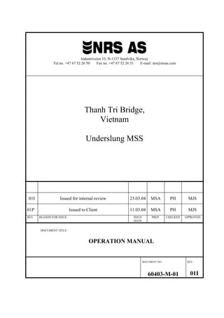
  • 1. Industriveien 33, N-1337 Sandvika, Norway Tel.no. +47 67 52 26 50 Fax no. +47 67 52 26 51 E-mail: nrs@nrsas.com Thanh Tri Bridge, Vietnam Underslung MSS 01I Issued for internal review 23.03.04 MSA PH MJS 01P Issued to Client 11.03.04 MSA PH MJS REV. REASON FOR ISSUE ISSUE DATE PREP. CHECKED APPROVED DOCUMENT TITLE: OPERATION MANUAL DOCUMENT NO.: REV.: 60403-M-01 01I
  • 2. Tel.: + 47 67522650 Fax: + 47 67522651 Underslung MSS for Thanh Tri Bridge Doc.no. 60403-M-01 OPERATION MANUAL Revision 01I Sheet no.: 2 TABLE OF CONTENT 1.0 Introduction .................................................................................................................................... 5 1.1 MAIN TECHNICAL DATA .................................................................................................................... 5 1.2 WIND CRITERIA.................................................................................................................................. 6 2.0 Description of Main Parts.............................................................................................................. 7 2.1 GENERAL............................................................................................................................................ 7 2.2 SUPPORTING BRACKET (SB)............................................................................................................... 7 2.3 LAUNCHING WAGON (LW) .............................................................................................................. 13 2.4 MAIN GIRDER (MG)......................................................................................................................... 15 2.5 NOSES (N)........................................................................................................................................ 16 2.6 TRANSVERSE TRUSS SYSTEM (TT)................................................................................................... 17 2.7 PLATFORMS (P) ................................................................................................................................ 20 2.8 FORMWORK (F) ................................................................................................................................ 21 2.9 SUSPENSION GALLOWS .................................................................................................................... 22 3.0 Assembly and erection................................................................................................................ 23 3.1 GENERAL.......................................................................................................................................... 23 3.2 LIFTING LUGS................................................................................................................................... 23 3.3 SAFETY ............................................................................................................................................ 24 3.4 BOLTED CONNECTIONS .................................................................................................................... 25 3.5 REQUIRED EQUIPMENT AND STORAGE FACILITIES............................................................................. 27 3.6 SUPPORTING BRACKET (SB)............................................................................................................. 28 3.7 PLATFORMS ON THE SUPPORTING BRACKETS:.................................................................................. 30 3.8 LAUNCHING WAGON (LW) .............................................................................................................. 31 3.9 MAIN GIRDER (MG)......................................................................................................................... 32 3.10 PLATFORMS ON MAIN GIRDERS: ...................................................................................................... 33 3.11 TRANSVERSE TRUSS SYSTEM (TT)................................................................................................... 34 3.12 MAIN GIRDER COUNTERWEIGHTS .................................................................................................... 37 3.13 NOSES (N) ....................................................................................................................................... 38 3.14 LONGITUDINAL LAUNCHING DEVICE ............................................................................................... 41 3.15 TRANSVERSE LAUNCHING DEVICE................................................................................................... 42 3.16 POSITIONING OF MSS PRIOR TO CONCRETING .................................................................................. 42 3.17 EXTERNAL FORMWORK (E) ............................................................................................................. 43 3.18 STEP-BY-STEP ASSEMBLY........................................................................................................ 45 4. 0 Preparations for concrete ........................................................................................................... 46 4.1 SAFETY ............................................................................................................................................ 46 4.2 INTRODUCTION................................................................................................................................. 46 4.3 CAMBERING ..................................................................................................................................... 46 5.0 Concrete safety procedures ....................................................................................................... 48 5.1 SAFETY ............................................................................................................................................ 48 5.2 CONCRETING SEQUENCE .................................................................................................................. 48 5.3 CHECK LIST PRIOR TO START CONCRETING ...................................................................................... 50 6.0 Launching safety procedures..................................................................................................... 51 6.1 SAFETY ............................................................................................................................................ 51
  • 3. Tel.: + 47 67522650 Fax: + 47 67522651 Underslung MSS for Thanh Tri Bridge Doc.no. 60403-M-01 OPERATION MANUAL Revision 01I Sheet no.: 3 6.2 SEQUENCES OF LAUNCHING ............................................................................................................. 51 7.0 Dismantling................................................................................................................................... 55 7.1 SAFETY ............................................................................................................................................ 55 7.2 DISMANTLING .................................................................................................................................. 55 8.0 Maintenance of hydraulic equipment......................................................................................... 56 9.0 Enclosures.................................................................................................................................... 57 9.1 DRAWING LIST ................................................................................................................................. 58 9.2 HYDRAULIC EQUIPMENT .................................................................................................................. 59 9.3 GREASE (MOLYCOTE PG-75)........................................................................................................... 60 9.4 PLASTIC GLIDING PLATE (PEHD-1000)........................................................................................... 61 9.5 CONTRACTORS ASSEMBLY DRAWINGS ............................................................................................ 62
  • 4. Tel.: + 47 67522650 Fax: + 47 67522651 Underslung MSS for Thanh Tri Bridge Doc.no. 60403-M-01 OPERATION MANUAL Revision 01I Sheet no.: 4 LIST OF REVISIONS Rev. Title Date: Rev. chapter: Sign- off: 01P Issued to client 11 March 04 - MJS 01I Issued for internal review 23 March 04 MJS
  • 5. Tel.: + 47 67522650 Fax: + 47 67522651 Underslung MSS for Thanh Tri Bridge Doc.no. 60403-M-01 OPERATION MANUAL Revision 01I Sheet no.: 5 1.0 Introduction The MSS has been designed and engineered specifically for this project. However in terms of strength, elements may be reused for other projects with span and superstructure concrete weights as per the Thanh Tri Bridge project. Use in other projects will require redesign and rechecking to verify structural integrity and adequacy. 1.1 Main Technical Data • Overall length – Max Span casting 60 m • Width of superstructure 15.8 m • Weight of superstructure 33.5 t/m • Outer width Main Girders, when concreting 14.5 m • Outer width Main Girders, when launching 22.2 m • Outer width Brackets 23.6 m • Outer width top superstructure, platform 18 m • Configuration height of MSS for concreting 10.200 m (Fixed Dimension) - Centreline of pier soffit to Base plate of Supporting bracket • Pier distance 50 m (Fixed) • Depth of Main Girders 3.6m • Max. Longitudinal Launching slope +/- 1% Total weights approx.: • Main Girders incl. Nose Joint 1 Pc. 300 t • Transverse Beams 52 t • Noses Front and Rear 59 t • Launching Wagon 28 t • Supporting Brackets 124 t • Support Struts 24 t • Platforms 30 t • External Formwork 182 t • Suspension Gallows 12 t • Internal Formwork (by OSJV) TBC TOTAL: 811 t
  • 6. Tel.: + 47 67522650 Fax: + 47 67522651 Underslung MSS for Thanh Tri Bridge Doc.no. 60403-M-01 OPERATION MANUAL Revision 01I Sheet no.: 6 1.2 Wind Criteria The MSS is designed for the following critical wind speed (CWS): • CWS during launching 12 m/s. • CWS during concreting 22 m/s • CWS MSS secured 38 m/sec
  • 7. Tel.: + 47 67522650 Fax: + 47 67522651 Underslung MSS for Thanh Tri Bridge Doc.no. 60403-M-01 OPERATION MANUAL Revision 01I Sheet no.: 7 2.0 Description of Main Parts 2.1 General Some of the parts involved will slide on PEHD-1000, which is similar to PTFE (Teflon). It is therefore extremely important to always store the equipment on wood or similar to avoid direct contact with ground; due to working conditions and time constraints on some previous projects the equipment was not stored properly and this has led to enormous problems because dirty steel parts did not slide as planned. Note, that all main parts are numbered with section nos., e.g. G-1000, N-1003, etc. (G for Main Girder, N for Nose). This reference is used on all drawings. Pre-assembling of connecting parts in the workshop will reduce the time required for assembly of the MSS at the jobsite, where the conditions can never be as good as in the workshop. The availability of tools is rather limited and access more difficult on the site. 2.2 Supporting Bracket (SB) (See drawings 350 - 381 Struts to Ground 360 - 362) The supporting brackets are designed to transfer the load from the main girders to the pile cap. They are located on each side of the pier, and connected together by tension bars. The load is transferred to the pile cap using 2 methods: 1. Struts to the ground interfacing with the SB and pile cap (a plinth is precast at the required level in order to obtain the correct height) 2. Corbel – A precast concrete corbel is located on the pier at a preset height. A third pair of SB is needed for the forward pier during launching. Required force in the tension bars is F=500 KN /bar both for upper (sixteen bars) and lower (two bars). To ease transport and assembling, each bracket is divided into four main parts, which have to be bolted together on site. For set-up of vertical height refer to drawing 101 for details.
  • 8. Tel.: + 47 67522650 Fax: + 47 67522651 Underslung MSS for Thanh Tri Bridge Doc.no. 60403-M-01 OPERATION MANUAL Revision 01I Sheet no.: 8 Figure 2.2a: Support Bracket General View Figure 2.2b: Support Bracket Close Up
  • 9. Tel.: + 47 67522650 Fax: + 47 67522651 Underslung MSS for Thanh Tri Bridge Doc.no. 60403-M-01 OPERATION MANUAL Revision 01I Sheet no.: 9 Figure 2.2c: Support Bracket Main Components Figure 2.2d: Upper section side elevation
  • 10. Tel.: + 47 67522650 Fax: + 47 67522651 Underslung MSS for Thanh Tri Bridge Doc.no. 60403-M-01 OPERATION MANUAL Revision 01I Sheet no.: 10 Figure 2.2e: Upper section plan view The upper section of the supporting bracket makes contact with the pier at two locations. These contact points consist of bolted on steel pedestals machined to the pier profile, refer drawing 350. 20mm thick neoprene shore 60 pads are screwed to the pedestals to prevent damage occurring to the concrete pier. The steel pedestals have to be changed according to the pier type. The 20mm thick neoprene is interchangeable between the different types of pedestal. The upper section of the bracket has been split into three pieces for transportation purposes
  • 11. Tel.: + 47 67522650 Fax: + 47 67522651 Underslung MSS for Thanh Tri Bridge Doc.no. 60403-M-01 OPERATION MANUAL Revision 01I Sheet no.: 11 Figure 2.2f: Supporting Brackets lower section plan view Figure 2.2g Supporting Bracket lower section side view The lower section makes contact with the pier in three places. Two of the contact positions consist of bolt on pedestals similar to the upper section of the bracket. Bolt on pedestals detail can be found on drawing 355. The third contact location consists of 20mm neoprene bolted onto a flat plate; the plate is positioned at the centreline of the pier and so is not affected by a change in radius.
  • 12. Tel.: + 47 67522650 Fax: + 47 67522651 Underslung MSS for Thanh Tri Bridge Doc.no. 60403-M-01 OPERATION MANUAL Revision 01I Sheet no.: 12 Figure 2.2h: Strut to ground front view Figure 2.2i: Strut to ground plan view The struts to ground are secured back to the pier with two tension bars; these tension bars are not stressed, just tightened using a spanner. The plan view, figure 2.2i shows the struts to the pier from the horizontal tie beam. The struts have to be extended with bolt on sections due to the different pier types. Neoprene between the strut and concrete is not required, as the strut is not stressed to the pier.
  • 13. Tel.: + 47 67522650 Fax: + 47 67522651 Underslung MSS for Thanh Tri Bridge Doc.no. 60403-M-01 OPERATION MANUAL Revision 01I Sheet no.: 13 2.3 Launching Wagon (LW) (Refer drawings 300 - 319) The Launching Wagons are the guiding supports for the MSS girders and an essential part of the system. They only carry loads during launching. Counteracting bearings on the outer webs are installed for safety reasons during launching and are generally not under load; the counter acting bearing plates must be removed after Transverse Beams have been connected to each other and prior to raising the Main Girders. With the rails in contact with the sliding pads, the transverse cylinder pulls / pushes the Main Girder transversally in steps of 250 or 500 mm movement. The cylinders for longitudinal launching shall be used at the centre pier. They push the MSS longitudinally in steps of 500 or 1000 mm. They are designed to pull the MSS in the reverse direction when required. Figure 2.3a Launching Wagon General View
  • 14. Tel.: + 47 67522650 Fax: + 47 67522651 Underslung MSS for Thanh Tri Bridge Doc.no. 60403-M-01 OPERATION MANUAL Revision 01I Sheet no.: 14 Figure 2.3b Launching Wagon Front Elevation Figure 2.3c: Outer sliding bearing Figure 2.3d: Inner sliding bearing
  • 15. Tel.: + 47 67522650 Fax: + 47 67522651 Underslung MSS for Thanh Tri Bridge Doc.no. 60403-M-01 OPERATION MANUAL Revision 01I Sheet no.: 15 2.4 Main Girder (MG) (Refer drawings 150 - 199) Two box girders, b = 1.8 m, h = 3.6 m, L = 62.725 m are designed as plate structures. Thickness of the plates varies between 10 and 70 mm. For platforms see chapter 3.6. The Main Girders are fitted with rails under the webs. These rails are designed for launching on sliding pads. At locations where the Main Girders shall be jacked up, the inner web is stiffened with inclined plates. The Main Girders are divided in sections 8.0-12.0m for transport and connected together on site by bolting. The main girder splice joints are designed as friction connections, and shall be pre-stressed according to the turn of the nut method detailed in chapter 3.4 of this manual. At each end a nose joint connection is welded to the Main Girders, allowing adjustment of the horizontal angle between the Main Girder and the Nose. The Main Girders are equipped with lifting lugs designed for 40 t each. When lifting the whole Main Girder, all 4 lifting lugs at the end sections must be used. (One crane at each end) A pushing rail is located at the centre underneath the Main Girder. Ten number nine tonne concrete counter weights are connected to the outer web of each main girder, refer drawing 192; the counter weights balance the MSS during longitudinal launching Figure 2.4 Main Girder
  • 16. Tel.: + 47 67522650 Fax: + 47 67522651 Underslung MSS for Thanh Tri Bridge Doc.no. 60403-M-01 OPERATION MANUAL Revision 01I Sheet no.: 16 2.5 Noses (N) (See also drawings 250 - 299) A nose at both ends extends each Main Girder. The Front and rear nose are built up in 2 sections. The outer dimensions of the noses are equal to the Main Girder’s. The Noses are space trusses built up of H - and angle profiles. They are fitted with only one rail located on the inner chord of the truss. In order to allow some vertical and horizontal movements of the Noses, adjustable bolted joints have been designed, refer drawing 260 for horizontal adjustment, located at the connection with the Main Girder, and drawings 268 & 269 for vertical adjustment, located on the top chord between the two nose elements. Access platforms running the entire length are located inside the noses. One stressing / working platform is located between the two front noses, cantilevering from the first section of each. Figure 2.5 : Front and rear nose
  • 17. Tel.: + 47 67522650 Fax: + 47 67522651 Underslung MSS for Thanh Tri Bridge Doc.no. 60403-M-01 OPERATION MANUAL Revision 01I Sheet no.: 17 2.6 Transverse Truss System (TT) (See also drawings 200 - 204) Eleven transverse beams connect the two main girders together; the beams are positioned 5.5 to 6m apart along the main girder. The transverse beams bolt to upper and lower connection plate on the inner web of each main girder The transverse beams support the external bottom soffit formwork at five locations. The bottom soffit is connected to the transverse beams using screw jacks. These screw jacks allow the level of the bottom soffit panels to be adjusted to the required camber. The jacks only carry the weight of the formwork and are easy to adjust. Each transverse beam is split into three sections refer figure 2.6a. Section 1 is connected to the RHS main girder while section 3 is connected to the LHS main girder. Section 2 and 3 of the transverse beams are connected using a hinged joint, which allows section 2 to be rotated 90 degrees horizontally relative to section 3. A locking system is used to restrain the beam during side shifting when the transverse beams are joined together. Section 2 is joined to section 1 using tension bars. The connection plates are guided together using tapered pins on the top and bottom chord. There are 10 type 1 and 1type 2 Transverse Beams. Type 2 beam is required to fold in the opposite direction to type 1 beam- refer to figure 2.6b. Figure 2.6a: Transverse beam
  • 18. Tel.: + 47 67522650 Fax: + 47 67522651 Underslung MSS for Thanh Tri Bridge Doc.no. 60403-M-01 OPERATION MANUAL Revision 01I Sheet no.: 18 Figure 2.6b: Plan view of TB9 and TB8 Figure 2.6c: Transverse beams split
  • 19. Tel.: + 47 67522650 Fax: + 47 67522651 Underslung MSS for Thanh Tri Bridge Doc.no. 60403-M-01 OPERATION MANUAL Revision 01I Sheet no.: 19 Figure 2.6d: Transverse beams folded
  • 20. Tel.: + 47 67522650 Fax: + 47 67522651 Underslung MSS for Thanh Tri Bridge Doc.no. 60403-M-01 OPERATION MANUAL Revision 01I Sheet no.: 20 2.7 Platforms (P) See also drawings 219 - 220 Ladders on Main Girder 214 - 218 Platforms on Transverse Beam 230 - 231 Platforms on Nose 238 - 239 Bottom slab platforms 371 – 373 Supporting bracket platforms Working Platforms are located on the supporting brackets, inside and between the noses and inside the main girders. Ladders and staircases allow access between various Platforms. Note that installation of Platforms in section 4.2 refers to each unit (Main Girder, Nose, Transverse Trusses, etc.). These platforms give access to all working areas, including all hydraulic equipment.
  • 21. Tel.: + 47 67522650 Fax: + 47 67522651 Underslung MSS for Thanh Tri Bridge Doc.no. 60403-M-01 OPERATION MANUAL Revision 01I Sheet no.: 21 2.8 Formwork (F) The Formwork consists of steel frames covered by steel sheets. 2.8.1 External Formwork Refer drawings 400 - 473 External Formwork includes bottom slab, web and top slab formwork. The bottom slab is split into 3 sections, two side panels, 3510mm and 3198mm wide and a middle panel 3792mm wide. Prior to launching forward the middle section of the bottom slab is folded vertically 90 degrees using a hydraulic jack; the middle section can only be folded after section 2 of the transverse beams has been folded. Adjustment of slope, cross fall and cambering is done by mechanical jacks for the bottom slab panels and by spindles for top and web panels. Figure 2.8.1 External Formwork
  • 22. Tel.: + 47 67522650 Fax: + 47 67522651 Underslung MSS for Thanh Tri Bridge Doc.no. 60403-M-01 OPERATION MANUAL Revision 01I Sheet no.: 22 2.9 Suspension Gallows ( Ref. drwg. -600 to -601 ) The Suspension Gallows consists of a beam supported by the rear main hydraulic jacks, 2 sets of 10 tension bars suspend the main girders during pouring. The beam is supported directly over the webs of the finished bridge superstructure. This system is dependent on a “block out” located in the previously cast section opening in the bridge deck for the sets of bars to be guided through. Fig 2.9.a: Suspension Gallows For easier handling, the Suspension Gallows is equipped with lifting lugs. The Suspension Gallows incl. legs are pre-assembled and will be lifted up in one piece.
  • 23. Tel.: + 47 67522650 Fax: + 47 67522651 Underslung MSS for Thanh Tri Bridge Doc.no. 60403-M-01 OPERATION MANUAL Revision 01I Sheet no.: 23 3.0 Assembly and erection 3.1 General This section covers relevant issues for the assembly and erection of the MSS. The MSS consists of a large number of components, which need to be put together in a predefined order and in accordance with specific requirements. This section describes the necessary steps for assembling the structure. To simplify the assembly, all Sections are marked with section number and weight. Items without any section number are marked with an Item number. Examples of Items are G1, T1, and N701 etc. In this chapter all assembly operations will refer to these numbers. This Chapter of the report is built up as follows: • Lifting Lugs • Safety considerations • Workshop pre-assembly • Site conditions • Bolted connections • Site assembly 3.2 Lifting Lugs Sections are outfitted with lifting lugs whenever this is required for safe handling during assembly. Each lifting lug has a number referring to the lifting drawing 800. This drawing includes information about the lifting capacity, allowed lifting angles and size of shackles. Lifting Lugs on Main Girder Angle Drwg No Tag No SWL (tonne) α1 α2 β1 Shackle SWL (tonne) Purpose Lifting Lugs on Nose Angle Drwg No Tag No SWL (tonne) α1 α2 β1 Shackle SWL (tonne) Purpose Lifting Lugs on Launching Wagon Angle Drwg No Tag No SWL (tonne) α1 α2 β1 Shackle SWL (tonne) Purpose
  • 24. Tel.: + 47 67522650 Fax: + 47 67522651 Underslung MSS for Thanh Tri Bridge Doc.no. 60403-M-01 OPERATION MANUAL Revision 01I Sheet no.: 24 Lifting Lugs on Supporting Bracket Angle Drwg No Tag No SWL (tonne) α1 α2 β1 Shackle SWL (tonne) Purpose 3.3 Safety Safe handling of large steel structures like this MSS often requires detailed analysis of stresses and deflections during various stages of the erection works. Some times special handling equipment must be built and special temporary stiffening and bracing has to be provided during construction. NRS will on request answer questions concerning these items and also - when agreed in advance - carry out needed engineering, design and analysis. As with any specialised equipment, extreme care and constant awareness is required at all times. It is important that personnel responsible for the MSS operation have adequate knowledge and understanding of the system ensuring all operations are correctly executed, preferably with previous experience in operating similar heavy lifting equipment. Checklists are required to be completed for every span to prevent any critical items being overlooked. All operatives should be made fully aware of the possible incidents that can occur due to negligence. If for any reason an unexpected incident occurs, common sense should prevail and operations should STOP until a reasonable explanation is found. Though each project has special features, which shall be taken into consideration in developing the most advantageous erection plan, some typical main procedures are briefly described below. A safety plan for «ERECTION» shall be made in advance, including «hazard analysis» for possible critical issues, in order to secure safe operation. Attention has to be paid to some issues such as temporary access and working platform connections during installation.
  • 25. Tel.: + 47 67522650 Fax: + 47 67522651 Underslung MSS for Thanh Tri Bridge Doc.no. 60403-M-01 OPERATION MANUAL Revision 01I Sheet no.: 25 3.4 Bolted Connections 3.4.1 General All bolted connections shall be in accordance with ENV 1090-1, Chapter 8 - Mechanical Fastening. Deviation from described standard shall be approved in advance by NRS. 3.4.2 Use of Washers For 8.8 bolts a washer shall be used under the bolt head or nut, whichever is to be rotated. For 10.9 bolts a washer shall be used under bolt head and the nut. 3.4.3 Tightening of non-preloaded bolts Each bolt assembly shall be brought to a snug-tight connection without overloading the bolts. Note: The term ”snug-tight” can generally be identified as that achievable by the effort of one man using a normal sized spanner without any extension arm, and be set as the point at which a percussion wrench starts hammering. 3.4.4 Tightening of preloaded bolts Prior to tightening the bolt, the contact surface has to be checked and satisfy classification “A” in accordance to ENV 1090-1, Chapter 8.8. Classification of friction surface: Surface blasted with shot or grit, with any loose rust removed, not pitted. 3.4.5 “Turn-of-the–nut method” The “turn-of-the-nut method” shall be used for tightening bolts requiring pre-load. 1. Each bolt assembly to be brought to a snug-tight connection. 2. The bolt to be finally tightened by applying the required rotation stated in table 5.
  • 26. Tel.: + 47 67522650 Fax: + 47 67522651 Underslung MSS for Thanh Tri Bridge Doc.no. 60403-M-01 OPERATION MANUAL Revision 01I Sheet no.: 26 Table 5 Turn-of-the-nut method: indicative required rotation for final tightening of Grade 8.8 bolts Total nominal thickness of parts to be joined (including all packs and washers) Total angle of rotation to be applied, beyond the ”snug-tight” condition Degrees 120 160 180 210 240 < 2d > 2d but < 4d > 4d but < 6d > 6d but < 8d > 8d but < 10d > 10d No indication Note 1: Where the surface under the bolt head or nut (allowing for tapered washers, if used) is not perpendicular to the bolt axis, the required angle of rotation should be determined by testing. Note 2: Values for grade 10.9 bolts should be determined by testing. 3.4.6 Use of Torque-wrench If torque-wrench is used, the following procedure is to be followed: 1. The first five (5) bolt connections of each separate bolt dimension shall be tightened according to the turn-of-the-nut method. 2. The torque-wrench to be calibrated against the highest value of the five test-bolt connections. 3. All the bolts shall be tightened to the calibrated torque. 3.4.7 Tightening / Checking Procedure The following procedure should be followed for tightening and checking of the bolts: 1. Bring bolts to snug tight fit. 2. Mark the nut and plate with chalk or paint 3. Rotate the nut as specified in table 5. The angle is measured using the mark on the nut and the plate. 4. Tighten all bolts as detailed in stages 1 to 3. 5. Visually inspect 100% of bolts to ensure mark on nut has moved through correct angle. 6. Calibrate torque wrench as detailed in 3.3.6 7. Randomly check 15% of all bolts using calibrated torque wrench. 8. If one bolt fails check an additional 15% of all bolts with the calibrated torque wrench. 9. If another bolt fails check 100% of the bolts with the torque wrench.
  • 27. Tel.: + 47 67522650 Fax: + 47 67522651 Underslung MSS for Thanh Tri Bridge Doc.no. 60403-M-01 OPERATION MANUAL Revision 01I Sheet no.: 27 3.5 Required equipment and storage facilities. 3.5.1 General The MSS structure shall be assembled and erected by companies with the necessary skill and equipment of adequate size and capacity. Skill is to be understood as skill in planning, transportation, handling, assembling, erection, dimensional control and inspection. The workmen shall have passed a qualification test. Workers without formal qualification in this type of structure shall work under supervision of skilled personnel. It is assumed that the Contractor will have available suitable cranes, which are able to lift all modules to the required position on site. Also auxiliary crane(s) must be available for lifting individual sections such as formwork. Furthermore a suitable vehicle must be available for transporting the pre-assembled module from the pre-assembly location to within reach of the cranes. This section describes the following issues related to the site conditions: • Required equipment • Main part storage 3.5.2 Assembly and erection cycle time Estimated assembly schedule: (5) Working days per MG and four (4) days for supporting brackets. Seven (7) working days for transverse beam and bottom slab. Two (2) days per nose. It’s assumed around 30 - 45 working days for the complete assembly of the MSS. 3.5.3 Equipment and Erection Method The outlined assembly and erection method indicated in this manual is based on the availability at site of necessary equipment for storage, temporary supporting and handling of all the MSS parts. Therefore, depending on for example the erector’s preferences, site conditions, the availability of equipment, crane capacity, etc, the method of erection may vary. 3.5.4 Storage of Main Parts If possible the MSS components should be stored in a clean environment and kept as dry as possible. The following items shall be protected: o Main Girder sections shall never be stored directly on the ground in order to keep the rails and other parts clean. o All mechanical items shall be protected from rain, dust, etc. including press-keys, nuts, bolts & washers. o All hydraulic equipment shall be protected for rain, dust, etc. If possible hydraulic hoses should be stored in an air-conditioned container, high heat / humidity will destroy the hose over a period of time.
  • 28. Tel.: + 47 67522650 Fax: + 47 67522651 Underslung MSS for Thanh Tri Bridge Doc.no. 60403-M-01 OPERATION MANUAL Revision 01I Sheet no.: 28 Never store Main Girder, Noses or other equipment directly on the ground in order to keep the rails or other parts clean (INCREASED FRICTION). Protect all hydraulic equipment against rain, dust, etc. Note that humidity and salinity in the air close to the sea is high, and corrosion starts immediately. 3.6 Supporting Bracket (SB) (See drawings 350 – 399) The recommended assembly and erection sequence of the bracket is described below. Due to transportation constraints each side of the supporting brackets are divided into two main sections. The upper section is further divided into 3 parts due to the width of the main transverse beam. Prior to erecting the bracket on the pier the upper section must be completely assembled. Depending on the height of the pier the proper combination of struts to ground must be calculated and erected. The support pad for the struts to ground is a concrete plinth with four cast insitu shear pins. The contractor must determine the level of the concrete plinth. Note: 1 When tightening the bolts connecting B-1001 to B-1002, the required force on each nut is 205 kN for all M24- 8,8 bolts. The two parts of the bracket are now ready to be lifted and connected to the strut to ground, and fixed to the pier. A temporary support system has been provided in the pier when assembling the lower half of the bracket B-1004 on to the struts to ground or the precast corbel, refer figure 3.6a. The two lower tension bars will then be tightened, but not pre-stressed. Lift the upper half of the support bracket and connect to lower half. The contact points between support bracket and pier column consist of bolt on steel plates. Ensure the correct support pads have been connected to the bracket. Note: 2 Both Supporting Brackets will be tightened together by means of 2 x 8 upper, and 2 x 1 lower Tension bars. The required force is F=500 kN /bar, upper & lower bars. The tension bars connecting the struts to ground to each other must not be stressed.
  • 29. Tel.: + 47 67522650 Fax: + 47 67522651 Underslung MSS for Thanh Tri Bridge Doc.no. 60403-M-01 OPERATION MANUAL Revision 01I Sheet no.: 29 If two cranes are available both brackets can be lifted simultaneously. Access for labourers must be planned in advance. Note: 3 The tolerance for installation must be checked: (At tip of long. beam) Direction Tolerance in mm Tolerance in degree Transversally 40 0,15° Vertically 20 0,15° Longitudinally 20 0,15° Figure 3.6.a: Temporary support system for lower section of support bracket Note: 4 Tension bars can be stressed and distressed only 50 times. After 50 times tension bars must be changed. Tension bars that have been bent cannot be used. Never drop tension bars.
  • 30. Tel.: + 47 67522650 Fax: + 47 67522651 Underslung MSS for Thanh Tri Bridge Doc.no. 60403-M-01 OPERATION MANUAL Revision 01I Sheet no.: 30 3.7 Platforms on the Supporting Brackets: Ref. drawings 371 to 373. Figure 3.7a Upper level Platforms on the Supporting Brackets Figure 3.7b Lower level Platforms on the Supporting Brackets
  • 31. Tel.: + 47 67522650 Fax: + 47 67522651 Underslung MSS for Thanh Tri Bridge Doc.no. 60403-M-01 OPERATION MANUAL Revision 01I Sheet no.: 31 3.8 Launching Wagon (LW) All launching cylinders, transverse cylinders, pumps etc. are hydraulically and electrically tested prior to shipment to Vietnam. Prepare plastic gliding plates as well as sliding plates (PEHD-1000), and install according to drawings 300-311. Note: 5 Plastic gliding plates are designed according to certain friction factors. The use of grease, preferably MOLYCOTE PG-75 grease, is required. Apply grease prior to each installation / use / sliding movement. Install hydraulic cylinders for longitudinal and transverse movement, and fix them to the bracket as well as to the Launching Wagon. NB! The cylinder for longitudinal movement shall be installed with the “braking valve” pointing away from the Pier The hydraulic pump to be installed as shown on drawing 300. Check the level of the inner and outer bearing. They should be at the same level. If there is a level difference at this stage of assembly stop and find out why. Any level difference between the inner and outer bearing will affect the level of the main girder and the subsequent transverse beam assembly.
  • 32. Tel.: + 47 67522650 Fax: + 47 67522651 Underslung MSS for Thanh Tri Bridge Doc.no. 60403-M-01 OPERATION MANUAL Revision 01I Sheet no.: 32 3.9 Main Girder (MG) (See also drawings 150 – 209 and 250) Due to limited craneage the contractor has decided to use temporary towers when installing the main girder, refer to the contractors drawings in section 9.5 of this manual. The main girder will be lifted up onto the temporary supports two boxes at a time using only one crane. Main girder installation procedure as follows: 1. Position the first module on temporary supports approximately 1000mm of the ground. 2. Place four 10 tonne bottle jacks beneath the launching rails and close to the splice joints. 3. Adjust the first main girder module to the correct level. 4. Place wedge shaped steel packers between the temporary supports and the launching rail and release the four bottle jacks. 5. Check the level of the first module to ensure the level is still correct. 6. Position the second module on temporary supports 10mm away from the first module. 7. Level the second module using the four bottle jacks and loosely connect the splice plates joining the first module to the second module. 8. Place wedge shaped steel packers between the temporary supports and the launching rail and release bottle jacks. 9. Check level of second module to ensure it is correct relative to the first module. 10. Tighten bolts in the splice plates joining the first module to the second module using turn of the nut method. 11. The two joined boxes are lifted onto the temporary towers, refer drawings contained in section 9.5 of this manual. The levelling procedure just described above (6 to 10) will then have to be followed again before joining each of the double boxes together. 12. The two completed main girders should each be positioned 10mm further away from the span centre line; this will allow temporary installation of fully assembled transverse beam TB1 and TB9. 13. Assemble TB1 and TB9 at ground level and temporarily install on the main girders. 14. Jack main girders up using main jacks. 15. Remove temporary towers and shims on sliding bearings. 16. Lower the main girders back down onto the sliding bearings and connect longitudinal launching device. 17. Check the launching rails for damage. They have to run smooth over the joints due to the sliding plates on the launching wagon. Use grease along the entire length of the rails. 18. Check the level of the main girder; top of inside web and top of outside web should be at the same level. 19. Remove TB1 and TB9. Note: 6 Lifting lugs are designed with SWL (Safe Working Load) = 40 tons*: Ref. drawings 190 and 191 SWL = 40 tons, used 20 times for each girder. *: SWL-capacity is to be marked black on yellow background. For connection of Main Girder elements, see drawings 161 - 163
  • 33. Tel.: + 47 67522650 Fax: + 47 67522651 Underslung MSS for Thanh Tri Bridge Doc.no. 60403-M-01 OPERATION MANUAL Revision 01I Sheet no.: 33 Figure 3.9.a Main Girder on Supporting Brackets Keep the counter acting bearings (item L061- L064) and bolts ready when installing the Main Girder. They must be safely bolted whenever disconnecting transverse beams and during transverse launching. Note: 7 Prior to any longitudinal launching, COUNTER ACTING BEARINGS. refer drwg. 300 & 301 must be installed. Place a warning triangle (∇), informing - IN THE LOCAL LANGUAGE - about the importance of securing these locking plates to the Launching Wagon. 3.10 Platforms on Main Girders: Ref. drawing 214, 215 and 216.
  • 34. Tel.: + 47 67522650 Fax: + 47 67522651 Underslung MSS for Thanh Tri Bridge Doc.no. 60403-M-01 OPERATION MANUAL Revision 01I Sheet no.: 34 3.11 Transverse Truss System (TT) (See also drawings 200 - 211) Correct assembly of the transverse beams is extremely important to ensure a smooth operation when the MSS is split after concreting and rejoined after launching forward. Contractors who do not spend time assembling the transverse beams correctly will pay dearly in terms of time delay. Prior to site erection the transverse beams should have been trial assembled in the workshop. During trial assembly check for misalignment, twist and any distortion. Any errors discovered should be rectified in the workshop. Assembly of the transverse beams should be carried out as follows (dimensions given in this procedure must be checked and verified by the contractor): 1. Carry out a dimensional survey of all transverse beams. 2. Establish the span centre line on the two piers where the MSS is being erected. 3. Extend the centreline onto the forward pier (pier #3). 4. Either string a line between piers or have a surveyor on call during the entire transverse beam assembly. 5. Position inner web of RHS main girder 5443mm from the span centreline; check the transverse beam dimensional survey, if there is a transverse beam which has been fabricated too long then this offset will have to be increased. 6. Off set the centreline 2353mm to the RHS, this now marks the middle of the connection between section 1 and 2 of the transverse beams. 7. Install platforms and jack adapters on section 1 of TB 1, 8 and 11 before being lifted into position. 8. Install section 1of Transverse beam 1, 8 and 11 on the RHS main girder. 9. Ensure the face of the top and bottom connection plates (section 1 to section 2) are in line with the off set line marked on the pier (2353mm from the span centre line); shim the top and bottom connections between the transverse beam and main girder to adjust the position if necessary, refer figure 3.11a. The main girder may need to be side shifted further out if section 1 connection plates passes over the off set line. 10. Check alignment of section 1 (TB 1, 8 and 11) and tighten connection bolts to main girder. 11. Side shift RHS of main girder approximately 200mm away from the span centreline. 12. Position inner web of LHS main girder 5443mm from the span centre line. 13. Assemble section 2 and 3 of transverse beams 1, 8 and 11 on the ground, including platforms and jack adapters. 14. Lock section 2 to 3 of TB1, lift into position and connect to LHS main girder. 15. Ensure the face of the top and bottom connection plates (section 1 to section 2) are in line with the off set line marked on the pier (2353mm from the span centre line); shim the top and bottom connections between the transverse beam and main girder to adjust the position if necessary, refer figure 3.11a. The LHS main girder may need to be side shifted further out if section 1 connection plates passes over the off set line. 16. Side shift RHS main girder 200mm back towards the span centre line and connect transverse beams together. 17. Check that there are no gaps between the top and bottom connection plates of section 1 to 2; shim the top and bottom connections between section 3 transverse beam and LHS main girder to adjust the position if necessary. Tighten connection bolts between section 3 and LHS main girder.
  • 35. Tel.: + 47 67522650 Fax: + 47 67522651 Underslung MSS for Thanh Tri Bridge Doc.no. 60403-M-01 OPERATION MANUAL Revision 01I Sheet no.: 35 18. Side shift RHS main girder 200mm away from span centre line. 19. Install section 1 of TB2, 3, 4, 5, 6, 7, 8 and 10 on the RHS main girder. Line the face of the connection plates by stringing a line between TB1 and TB9. Tighten connection between main girder and section 1. 20. Install section 2 and 3 of TB2, 3, 4, 5, 6, 7, 8 and 10 on the LHS main girder. Line the face of the connection plates by stringing a line between TB1 and TB9. Do not yet tighten section 3 to the main girder. 21. Side shift RHS main girder back towards the span centreline and connect transverse beams together. 22. Check for gaps in the top and bottom connection between section 1 and 2, shim the connection between section 3 and the main girder if necessary to remove gaps. 23. Tighten bolts connecting section 3 to the LHS main girder. 24. Install horizontal bracing and longitudinal platforms. Figure 3.11a: Shim the connection between main girder and transverse truss
  • 36. Tel.: + 47 67522650 Fax: + 47 67522651 Underslung MSS for Thanh Tri Bridge Doc.no. 60403-M-01 OPERATION MANUAL Revision 01I Sheet no.: 36 Note: 8 The required force for bolting the upper part (T23) to the Main Girder is: F = 430 kN (each bolt) and for lower part (T22) F = 300 kN (each bolt). Figure 3.11b: Assembling of Transverse Truss, Jack Adaptor and Platforms on the Ground
  • 37. Tel.: + 47 67522650 Fax: + 47 67522651 Underslung MSS for Thanh Tri Bridge Doc.no. 60403-M-01 OPERATION MANUAL Revision 01I Sheet no.: 37 3.12 Main Girder Counterweights Ref. Drawings 192 and 193. Counterweights shall be connected to the lifting lugs on the top of the main girder by bars through the concrete beam. The counter-weights must be installed before the external formwork is placed on the transverse beams. Figure 4.12.a Main girder counterweights sectional view Figure 4.12.b Main girder counterweights plan view (one side of main girder only)
  • 38. Tel.: + 47 67522650 Fax: + 47 67522651 Underslung MSS for Thanh Tri Bridge Doc.no. 60403-M-01 OPERATION MANUAL Revision 01I Sheet no.: 38 3.13 Noses (N) Figure 3.13a: Plan view of front and rear nose The required lifting capacity for installing element 1, 2 of the rear and front nose is approximately 13.5 tonnes. If each element is lifted separately, the required capacity is approximately 7 tons. Nose installation procedure as follows: 1. Tack weld spacers G663 and G650 to the main girder male clevis, refer drawing 187. 2. Lift section 1 of the nose truss (N-1000 / N-1002) into position. It is easier to use two cranes to install the nose truss as the longitudinal gradient can be easily altered when trying to insert the male clevis into the female clevis. If only lifting with one crane check the longitudinal gradient of the lifted truss matches the main girder. 3. Insert pin bolts connecting the main girder to the top and internal bottom chord of the nose truss. Secure pin bolts in place using plates N202 and N210, refer drawing 258. Figure 3.13b: Plan view of top chord connection To main girder
  • 39. Tel.: + 47 67522650 Fax: + 47 67522651 Underslung MSS for Thanh Tri Bridge Doc.no. 60403-M-01 OPERATION MANUAL Revision 01I Sheet no.: 39 Figure 3.13c: Plan view of bottom chord connection To main girder 4. Install horizontal adjustment device N-1008 refer fig 3.13c. 5. Release section N-1000 / N-1002 from the crane. 6. Lift section 2 of the nose truss (N-1001 / N-1003) into position. 7. Insert the pin bolts connecting the inner and outer bottom chord of section 1 to section 2 refer figure 3.13d. Figure 3.13d: Plan view of bottom chord connection Section 1 to section 2
  • 40. Tel.: + 47 67522650 Fax: + 47 67522651 Underslung MSS for Thanh Tri Bridge Doc.no. 60403-M-01 OPERATION MANUAL Revision 01I Sheet no.: 40 8. While still holding section 2 with the crane assemble the vertical adjustment device N-1009. Insert lining plates into N-1009 until the level at the tip of section 2-nose truss is 150mm higher than the level at the connection between section 1 and section 2. 9. Install the stressing platforms on the front nose truss refer drawing 232 - 234. Note: 10 Steel shim plates of up to 200mm are available thus enabling adjustment of gap in the range + 100 mm. When adjusting, remove / add plates to change angle – vertical position of the end element. Use jack RCH-202 to adjust
  • 41. Tel.: + 47 67522650 Fax: + 47 67522651 Underslung MSS for Thanh Tri Bridge Doc.no. 60403-M-01 OPERATION MANUAL Revision 01I Sheet no.: 41 3.14 Longitudinal Launching Device Ref. Note 7 for counter acting plates. The longitudinal launching device should be installed according to the hydraulic operation manual refer enclosure 9.2. For further reference, see drawings 300, 308 and 309, which detail required position of pin bolts when launching forwards or backwards. Figure 3.14a: Longitudinal Launching device
  • 42. Tel.: + 47 67522650 Fax: + 47 67522651 Underslung MSS for Thanh Tri Bridge Doc.no. 60403-M-01 OPERATION MANUAL Revision 01I Sheet no.: 42 3.15 Transverse Launching Device Each launching wagon can slide transversely on top of the supporting bracket. Between the launching wagon and top of support bracket there are plastic gliding plates. The launching wagons are pushed or pull transversely using two double acting cylinders connected from the support bracket to the launching wagon. It is important to ensure these side shifting jacks have been connected correctly to the pump and that they both push and pull simultaneously. If the jacks have been connected incorrectly and act in opposite directions i.e. one pushes while the other pulls then it is possible to twist the launching wagon off the supporting bracket. Figure 3.15a: Side-Launching Cylinders 3.16 Positioning of MSS prior to concreting Now the MG shall be jacked up. The jacks are placed on the SB, inside the rails of the MG. The counter acting bearing must be removed before jacking. Note that bolts for launching must be removed after the rails have been clearly lifted off the pads (the launching cylinders piston would describe a curve and be pulled out!!). After the main jack piston has moved approx. 10-20 mm, the «cat» hits the lower plate of the jack support, and jacking of the girder starts. The locking collars shall be screwed down for every 30mm for safety reasons in case of a hose bursting or other hydraulic failure.
  • 43. Tel.: + 47 67522650 Fax: + 47 67522651 Underslung MSS for Thanh Tri Bridge Doc.no. 60403-M-01 OPERATION MANUAL Revision 01I Sheet no.: 43 When the correct elevation is reached (approx. 200m higher), the safety nut of the jack must be tightened before the oil pressure is relieved. 3.17 External Formwork (E) Refer drawings 400 - 489 Parts of the bottom slab, web and cantilever panels shall be pre-assembled in accordance with the shop drawings. 3.17.1 Bottom slab Reference is made to drawings 400 - 427. The bottom slab consists of 27 panels (9 x 3= 27) refer figure 3.17a. Figure 3.17a Plan of bottom slab formwork Bottom slab installation procedure as follows: 1. Adjust mechanical screw jacks E-1300 (refer drawing 261) according to camber values detailed in section 4.3 of this manual. Camber values have been given at the span centre line so it will be necessary for the contractors Engineering department to calculate the value at each screw jack. Setting the correct level prior to installation of the bottom panels will save a lot of hard work later on. 2. Erect panel E-1002. This panel can be lifted using a sling around the panel; temporary lifting lugs are not required. 3. Assemble panel E-1020 and E-1011 at ground level according to drawing 447 and attach a temporary strut between both panels. 4. Lift assembled panels E-1020 / E-1011 using the temporary lifting lugs on panel E-1011 and the web panel lugs on panel E-1020. 5. Position panels E-1020 / E-1011 on the mechanical screw jacks and secure. 6. Lock panel E-1011 to E-1002 using one number ∅26.5mm tension bar. 7. Check level of assembled bottom slab panel and adjust if necessary before assembling next set of panels. 8. Continue erecting bottom slab panels working backwards from the forward pier. 9. The cantilever panels E-1001, E-1010 and E-1019 can be erected at any time but must follow the same sequence detailed in 1 to 7. 10. Remove all temporary lifting lugs. 11. Install adjustable support E-1304 refer drawing 462.
  • 44. Tel.: + 47 67522650 Fax: + 47 67522651 Underslung MSS for Thanh Tri Bridge Doc.no. 60403-M-01 OPERATION MANUAL Revision 01I Sheet no.: 44 NOTE: 11 Adjust cambering of bottom slab prior to installing web and deck slab panels, for cambering values refer section 4.3. 3.17.2 Top and web panels Reference is made to drawings 400, 431 – 489. Figure 3.17b Plan of web and wing formwork Assemble the web and wing formwork as follows: 1. Install adjustable supports E-1303 for the standard web / wing panels (E-1034, 1033, 1032, 1030, 1040, 1039, 1038 and 1036). The adjustable supports for these standard panels are pinned to lug L3, which is detailed on drawing 190 section B. 2. Lift the web panels into position; connect the web panel to the lug on the bottom slab formwork and the adjustable supports E-1303. Adjust the angle of the web panel using adjustable support E- 1303. 3. Lift the wing panel into position and bolt to the top of the web panel. Attach adjustable support E- 1303 to the wing panel and release from crane. 4. Adjust the level of the wing panel using adjustable supports E-1303 according to the camber levels detailed in section 4.3 of this manual. 5. Install adjustable supports E-1303 and E-1301 for web panels E-1031 and E-1037 at forward pier. The additional adjustable support E-1301 is required at the pier location as there is no bottom soffit formwork. 6. Install web panels E-1031 and E1037; connect adjustable supports and release from crane. 7. Lift wing panels E-1051 and E-1057 into position and bolt to web panels E-1031 and E-1037; connect adjustable support E-1030 to web panels and release from crane. 8. Adjust level of the wing panels using adjustable supports E-1303 according to the camber levels in section 4.3. 9. Web and wing panel XXXX located at the rear end of the MSS are installed on a sliding wagon. After the span has been concreted these panels are to be slid backwards on to the nose truss to allow the pier segment to be stressed transversely. 10. The sliding arrangement is detailed on drawing XXX and should be installed as follows:
  • 45. Tel.: + 47 67522650 Fax: + 47 67522651 Underslung MSS for Thanh Tri Bridge Doc.no. 60403-M-01 OPERATION MANUAL Revision 01I Sheet no.: 45 1. Bolt sliding rail to nose truss, ensure the correct line and level is achieved such that it matches the rail already welded to the main girder. Level can be adjusted by shimming the vertical support; line can be adjusted as the bolted flange connections have slotted holes. 2. Position the sliding wagon on the rails and clamp in position. 3. Install adjustable supports E-1303, 1302 and 1301 on the sliding wagon. 4. Lift web panels XXX and XXX into position on the sliding wagon, connect to adjustable supports, install cross bracing and release from crane. 5. Lift wing panels into position; connect adjustable supports and release from crane. 3.18 STEP-BY-STEP ASSEMBLY NO.: ACTION: CHAPTER: 1 Erect Supporting Brackets 2 Check tolerances as stated in NOTE – 3 3 Tighten Tension bars as stated in NOTE – 2 4 Install the Platforms (on the Brackets) 5 Erect the Launching Wagon and hydraulic components 6 Erect the Main Girders 7 Install the Counter Acting Bearing Plates, NOTE – 7 8 Install the Transverse Truss - NB: NOTE – 9 9 Assemble Platforms and ladders 10 Launch MSS into correct longitudinal position 11 Move MSS transversely and tighten TB and elevate 12 Erect Noses 13 Install the rest of the platform and ladders 14 Erect counterweights. 15 Install external Formwork Bottom slab first, adjust cambering 16 Install external formwork Web and deck slab, adjust cambering 17 Prepare and Lift up Internal Formwork and adjust 18 Check all installation, required forces on bolts, platforms, and so 19 Execute check according to checklist 6.0 The span is now ready for concreting.
  • 46. Tel.: + 47 67522650 Fax: + 47 67522651 Underslung MSS for Thanh Tri Bridge Doc.no. 60403-M-01 OPERATION MANUAL Revision 01I Sheet no.: 46 4. 0 Preparations for concrete 4.1 Safety A separate safety plan including hazard analysis shall be prepared with respect to all activities during concreting. 4.2 Introduction This procedure applies for concreting a typical span. The (launching and) positioning of the MSS and its formwork is completed. 4.3 Cambering Cambering is done to ensure the correct vertical curvature of the bridge and compensate for elastic deformations of the MSS due to its own weight and the weight of the concrete. This will be achieved by adjusting the height of the jacks below the bottom slab and the adjustable supports for top and web slab. In addition to all loads acting, impacts due to elongation of tension bars and cross-fall has been considered and included. The enclosed tabulated data only considers the deformation of the MSS due to concrete weight of the bridge superstructure. All other weights due to items such as steel structure (MSS self-weight), formwork, equipment, etc. are not included and must be adjusted for based by measurements at site. This means that, following erection of the MSS, the theoretical 0-line must be established by means of site surveyors. Please be aware that the possible interaction effects from concreting in neighbouring spans are not accounted for. This has to be considered by the bridge design engineer. The given cambering values are theoretical values, and should be treated accordingly at the 1st concreting. Eventual deviations should be monitored and implemented for the following on concreting.
  • 47. Tel.: + 47 67522650 Fax: + 47 67522651 Underslung MSS for Thanh Tri Bridge Doc.no. 60403-M-01 OPERATION MANUAL Revision 01I Sheet no.: 47 Note - 12: Values have been obtained assuming the concrete does not have any load carrying capacity during the concreting phase. This is applicable if the concreting operation is concluded in the course of 8-10 hours. Concrete will become self-supporting if the operation times are in excess of 8 - 10 hours. To what extent the concrete becomes self-supporting should be calculated by the bridge engineer, eventual deviations should be included in the cambering table. Vertical displacements due to weight of concrete (mm) c/L bridge Transverse frame No. Start span Typical span 1 2 3 4 5 6 7 8 9 10 11 12 Vertical displacements due to weight of concrete (mm) at Main girder Transverse frame No. Start span Typical span 1 2 3 4 5 6 7 8 9 10 11 12
  • 48. Tel.: + 47 67522650 Fax: + 47 67522651 Underslung MSS for Thanh Tri Bridge Doc.no. 60403-M-01 OPERATION MANUAL Revision 01I Sheet no.: 48 5.0 Concrete safety procedures 5.1 Safety When the survey has been completed, the check before start of concreting can start. The check should be executed and noted in the report (Checklist). A check before start of pouring should begin with a check of safety related items such as ladders, access platforms, safety nets and so on. All hydraulic units, jacks and lines incl. hoses and valves will be checked for leakage and repaired where necessary. A final visual check will represent the end of the check before start of concreting. The enclosed « sign-off » checklist is recommended to guarantee routine checks for each span prior to concreting. 5.2 Concreting Sequence 5.2.1 Longitudinal Direction Cantilever Spans: The concreting should start at the front pier column, continuing with the cantilever sections before concreting from the front pier and backwards to the previously concreted span. 5.2.2 Transverse Direction The concreting works has to be done symmetrically about the bridge centre. The top slab must be cast at side top panels before / at the same time as the web, to avoid uplift of internal formwork.
  • 49. Tel.: + 47 67522650 Fax: + 47 67522651 Underslung MSS for Thanh Tri Bridge Doc.no. 60403-M-01 OPERATION MANUAL Revision 01I Sheet no.: 49 Figure 5.2a: Concreting Sequence
  • 50. Tel.: + 47 67522650 Fax: + 47 67522651 Underslung MSS for Thanh Tri Bridge Doc.no. 60403-M-01 OPERATION MANUAL Revision 01I Sheet no.: 50 5.3 Check List prior to start Concreting SPAN P______ - P______ No. Description of check: Checked by Date Approved by: Date: 1 Safety: Platforms, ladders, safety nets. 2 Hydraulic lines, valves, etc., leakage test. 3 Main jacks: mechanical locking ring installed. 4 Bolts between Main Girders tightened. (Note 1) 5 Bolts between Main Girders and Transverse Beams tightened. (Note 1) 6 Tension bar between Transverse Beams tightened properly. 7 Tension bars fastened properly. 8 Pre-stressed bolts checked / spot-checked. (Note 1) 9 Block-outs installed where tension bars pass concrete later (Suspension Gallows). 10 Transversal jacks pulled inwards for protection. 11 Electric lines checked. 12 Survey of formwork and cambering. 13 Earthquake stays installed properly. 14 Stiffening from Supporting Bracket to the Piers installed properly. Note 1: To be checked every 10th span. EXECUTED BY:..................... DATE:......................... APPROVED BY:..................... DATE:.........................
  • 51. Tel.: + 47 67522650 Fax: + 47 67522651 Underslung MSS for Thanh Tri Bridge Doc.no. 60403-M-01 OPERATION MANUAL Revision 01I Sheet no.: 51 6.0 Launching safety procedures 6.1 Safety A separate safety plan including hazard analysis shall be made with respect to all activities during launching. 6.2 Sequences of Launching All hydraulic components required during the launching process are explained in the hydraulic manual contained in section 9.2 of this manual. 6.2.1 Launching - Relocation of Brackets During the concreting phase of a span, the rear pair of Supporting Brackets shall be dismantled and transferred to the forward pier and reinstalled. Before dismantling, all loose components have to be removed or safely fixed. To reduce the need of adjusting the Main Girders / Transverse Beams when they are connected, it is important, that the Supporting Brackets are placed in a very exact and correct position. See erection of Brackets for detailed information (chapter 4.5 and 8.3). 6.2.2 Launching - Lowering The launching operation is initiated by lowering the Main Girders using the main jacks. The oil pressure of the main jacks, both front and rear, is activated until it is possible to loosen the locking collars. The nuts are screwed up in steps of no more than 30mm – this for safety reasons in case a hose bursts or similar hydraulic failure. Lower the Main Girders (i.e. 30mm at one time front / rear) until the rails almost hit the pads of the rail bed. Connect launching cylinder and continue lowering until hitting the rail sits firmly onto the sliding bearings. The piston rods of the jacks are lowered a little more (falling by self weight), so that the rods become free of the jack-point. Note - 13: Make sure that the counter acting bearing (locking) plate of the Launching Wagon is now placed at the outer webs of the front support. 6.2.3 Side Launching – Outward direction Prior to side launching, the right hand side main girder must be locked in position against the forward and rear pier; The RHS is unstable until the bottom soffit panels have been folded 90 degrees. The stabilizing system is detailed on drawing 171. The side launching procedure is as follows: 1. Ensure screw jacks on RHS main girder are secured against the forward and rear piers. 2. Release the tension bars connecting section 1 to 2 of the Transverse truss.
  • 52. Tel.: + 47 67522650 Fax: + 47 67522651 Underslung MSS for Thanh Tri Bridge Doc.no. 60403-M-01 OPERATION MANUAL Revision 01I Sheet no.: 52 3. Side launch the LEFT HAND SIDE main girder 150mm until the locating pins are free. 4. Fold section 2 of the transverse beams, start at TB9 and work backwards. 5. Fold the bottom slab panels 90 degrees on the RHS main girder using the hydraulic jacks. 6. Continue side launching the LHS main girder until it can pass the forward pier. 7. Release the stabilizing system RHS main girder and side launch until clear of the forward pier. 6.2.4 Longitudinal Launching For longitudinal launching see chapter 11.3, hydraulic equipment. Due to the high capacity of the launching cylinder, the return is strong enough to move the MSS both forward and reverse (push & pull). In order to save time, launching steps of 1000mm are recommended, but steps of 500mm can also be executed. When the front nose is approaching the next pier, there may be need for transverse adjustment of the Launching Wagon to enable the rail to coincide with the guides. If the vertical gap between the rail and wheel is too large or negative, the element 1 (outer) of the Nose can be adjusted by means of the end plates/bolts between the upper flanges of element 1 and element 2. Some lining plates then have to be added or removed. A hydraulic jack must be used for adjusting. The Nose should make contact with the gliding plate on the launching wagon after the tip has been launched approximately 2m past the centre of the Launching Wagon. If this is not the case, adjustments of the nose shall be carried out. When the front of the Main Girder has reached and (somewhat) passed the front Launching Wagon, the counter bearing Locking Plate is installed. Then the counter bearing Locking Plate can be removed from the rear. When launching to the next span ensure the final position has been marked. If the main girder is launched too far it will have to be reverse launched into the correct position. When reverse launching the bolts in the launching device need to be changed. 6.2.5 Side Launching – Inwards Direction Before launching the girders towards each other, their respective position in plan should be carefully checked and adjusted if necessary. The procedure for joining the two sides of the MSS will be as follows: 1. Side launch RHS of MSS into position. 2. Install Stabilizing screw jacks against front and rear pier. 3. Raise the bottom soffit formwork 90 degrees. 4. Swing section 2 of the transverse beams 90 degrees into position and lock. 5. Side shift LHS of MSS until the stabbing cones on section 2 enter the funnel on section 1. 6. Adjust longitudinal position of LHS MSS if necessary to align the transverse beams. 7. Complete side shifting LHS of MSS and tighten tension bars, which connect section 1 to section 2. Do not pre-stress the tension bars. 8. Release stabilizing screw jacks between RHS main girder and the piers.
  • 53. Tel.: + 47 67522650 Fax: + 47 67522651 Underslung MSS for Thanh Tri Bridge Doc.no. 60403-M-01 OPERATION MANUAL Revision 01I Sheet no.: 53 If after side launching there are any gaps between the top or the bottom transverse truss connection plates then slight adjustment is required. Each launching wagon has jacking pedestals positioned on the outer side. When the main girder is to be rotated to close the gap at the top of the transverse beams, jacks will be placed below these pedestals and the launching wagon jacked up. The front and the rear-launching wagon must be jacked up at the same time. If there are gaps at the bottom of the transverse beams then the side shifting jacks can be activated to pull the LHS of the MSS in towards the RHS MSS. 6.2.6 Launching – Vertical Adjustment Remove counter acting bearing locking plates on the Launching wagons. Raise the main girders to the correct elevation using the front and rear main jacks. After the first span has been completed and the MSS launched forward, the Suspension Gallows will be lifted onto the cantilevered section. The supports of the SG are the two (rear) 600 t hydraulic jacks previously used on the rear support bracket for the first span. The tension bars are placed through the holes of the previously completed span and connected to the Main Girder. Connect the tension bars until good support. The jacks under the stressing gallows are raised until the bottom soffit comes into contact with the previously constructed span. Formwork ties are required between the previous concrete and the top and bottom slab panels, refer drawing 473. These formwork ties will prevent gaps from developing between the formwork panels and the previously constructed span during the concrete pour. Prior to loading the rear jacks: Whenever erecting the Suspension Gallows be aware and make sure, that the Suspension Gallows has been installed 100% horizontal. Make sure, that the jacks under the Suspension Gallows are located on steel plates, min. size 400x400x30mm and that these are embedded in high strength mortar, which shall compensate the cross-fall (lateral) in order to make sure that the Suspension Gallows is installed 100 % horizontal. Comment: The base plate dimension is dependent on the vertical force and concrete quality and has to be calculated accordingly. When the correct elevation has been reached ensure the main jack locking collars have been tightened. The oil pressure is relieved. The launching operation is now finished.
  • 54. Tel.: + 47 67522650 Fax: + 47 67522651 Underslung MSS for Thanh Tri Bridge Doc.no. 60403-M-01 OPERATION MANUAL Revision 01I Sheet no.: 54 6.3 Check-List prior to start Longitudinal Launching SPAN P_____ - P_____ No. Description of check: Checked by: Date: Approved: Date: 1 Safety: Platforms, ladders, safety nets. 2 Hydraulic lines, valves, etc., leakage test. 3 Launching Cylinder: bolts mounted and secured. 4 Rear pair of main jacks prepared for transfer to next bracket. 5 Platform on the Nose cleaned; all equipment removed. 6 Ladder (lower part) from Bracket to Main Girder removed? 7 Bolts at counter acting plates checked. 8 Electric lines checked, and length of electric lines satisfactory. 9 Survey of Supporting Brackets OK. 10 Grease (Molycote) applied to transverse sliding plates. (Note 1) 11 Earthquake stays removed. Note 1: To be checked prior to lowering the MSS. EXECUTED BY:..................... DATE:......................... APPROVED BY:..................... DATE:.........................
  • 55. Tel.: + 47 67522650 Fax: + 47 67522651 Underslung MSS for Thanh Tri Bridge Doc.no. 60403-M-01 OPERATION MANUAL Revision 01I Sheet no.: 55 7.0 Dismantling 7.1 Safety A separate safety plan including hazard analysis shall be made especially with respect to all dismantling activities incl. heavy lifts. 7.2 Dismantling Dismantling will happen in the reverse sequence of assembling. If the required crane capacity is on site, the Formwork, and the Main Girders, Transverse Beams & Noses will be lifted down. Finally the Supporting Brackets will be dismantled. If the existing crane does not allow such heavy lifts one or two temporary support(s) in the (middle of the) span may be required. Upon request NRS will assist in order to plan special dismantling procedures Incl. required drawings.
  • 56. Tel.: + 47 67522650 Fax: + 47 67522651 Underslung MSS for Thanh Tri Bridge Doc.no. 60403-M-01 OPERATION MANUAL Revision 01I Sheet no.: 56 8.0 Maintenance of hydraulic equipment Bolts in between the Main Girders and between Main Girders and Main Girder and Transverse Trusses: Checks to be executed (on nuts, not on bolts) before and after first concreting while spot-checks (*) will only be executed for every +/- 10th span. Prior to first concreting and after 1st concreting all pre-stressed bolts shall be checked while these bolts later will only be spot-checked (Note 1) every +/- 10th span. In case of bolts found to be loose or bolted less than required, bolts to be tightened. All electrical lines and connections are subject to a visual check. Hydraulic manuals from supplier is enclosed in Enclosure 9.2. (Note 1) In case of pre-stressed bolts found with less than the required force, all bolts of similar type and required force have to be checked.
  • 57. Tel.: + 47 67522650 Fax: + 47 67522651 Underslung MSS for Thanh Tri Bridge Doc.no. 60403-M-01 OPERATION MANUAL Revision 01I Sheet no.: 57 9.0 Enclosures 9.1 Drawing List 9.2 Hydraulic Equipment & Maintenance 9.3 Grease (MolycotePG-75) 9.4 Plastic Gliding Plate (PEHD-1000) 9.5 Contractors Assembly Drawings
  • 58. Tel.: + 47 67522650 Fax: + 47 67522651 Underslung MSS for Thanh Tri Bridge Doc.no. 60403-M-01 OPERATION MANUAL Revision 01I Sheet no.: 58 9.1 Drawing List
  • 59. Tel.: + 47 67522650 Fax: + 47 67522651 Underslung MSS for Thanh Tri Bridge Doc.no. 60403-M-01 OPERATION MANUAL Revision 01I Sheet no.: 59 9.2 Hydraulic Equipment
  • 60. Tel.: + 47 67522650 Fax: + 47 67522651 Underslung MSS for Thanh Tri Bridge Doc.no. 60403-M-01 OPERATION MANUAL Revision 01I Sheet no.: 60 9.3 Grease (Molycote PG-75)
  • 61. Tel.: + 47 67522650 Fax: + 47 67522651 Underslung MSS for Thanh Tri Bridge Doc.no. 60403-M-01 OPERATION MANUAL Revision 01I Sheet no.: 61 9.4 Plastic Gliding Plate (PEHD-1000)
  • 62. Tel.: + 47 67522650 Fax: + 47 67522651 Underslung MSS for Thanh Tri Bridge Doc.no. 60403-M-01 OPERATION MANUAL Revision 01I Sheet no.: 62 9.5 Contractors Assembly Drawings