SlideShare a Scribd company logo
1 of 30
Download to read offline
2023
Abdul Majid
(S32002006W)
College of Aerospace and
Civil Engineering
4/6/2023
Structural Health Monitoring of a Cable-Supported
Zhejiang Bridge
Structure Mechanical Performance Evaluation & Health
Monitoring
1
Table of Contents
Table of Figures............................................................................................................................................2
Table of Tables .............................................................................................................................................3
Abstract.........................................................................................................................................................4
1. Introduction...........................................................................................................................................4
2. Bridge Description................................................................................................................................5
3. Bridge Monitoring System....................................................................................................................6
3.1 Design and Implementation of the IAS.........................................................................................7
3.1.1 Sensor Systems .....................................................................................................................7
3.1.2 Data Acquisition and Transmission Module.......................................................................19
3.1.3 Software System .................................................................................................................20
3.2 Design and Implementation of the DMS ....................................................................................23
3.3 Design and Implementation of the EDS......................................................................................23
3.3.1 Data Processing Module .....................................................................................................23
3.3.2 Status Evaluation Module...................................................................................................24
3.4 Design and Implementation of the ASS......................................................................................24
4. Conclusions.........................................................................................................................................25
5. Future Trends......................................................................................................................................26
References...................................................................................................................................................28
2
Table of Figures
Figure 1Photograph of Zhijiang Bridge........................................................................................................5
Figure 2Overall workflow of the system ......................................................................................................7
Figure 3Layout of sensors on Zhijiang Bridge. ............................................................................................8
Figure 4Meteorological station.....................................................................................................................9
Figure 5Hygrothermograph ........................................................................................................................10
Figure 6GPS sensor.....................................................................................................................................11
Figure 7Wind and Structural Monitoring....................................................................................................12
Figure 8Hydrostatic level gauge .................................................................................................................13
Figure 9Stress and fatigue monitoring points on the box girder.................................................................14
Figure 10Welding crack monitoring points on the box girder....................................................................14
Figure 11Stress and fatigue monitoring points on the steel tower..............................................................15
Figure 12Strain gauges ...............................................................................................................................16
Figure 13Vibration sensor...........................................................................................................................18
Figure 14Acceleration sensor......................................................................................................................19
Figure 15Flowchart of data acquisition and transmission...........................................................................20
Figure 16External environment of the bridge.............................................................................................21
Figure 17Vibration of 4# tower and T7 box girder.....................................................................................21
Figure 18Displacement changes in the box girder......................................................................................22
Figure 19Tower shift...................................................................................................................................22
Figure 20Cable force...................................................................................................................................22
Figure 21Function and composition of the DMS........................................................................................23
Figure 22Flowchart during bridge condition evaluation.............................................................................24
3
Table of Tables
Table 1Meteorological station technical specifications. ...............................................................................8
Table 2Hygrothermograph technical specifications......................................................................................9
Table 3Weigh-in-Motion system technical specifications..........................................................................10
Table 4Technical specifications of the GPS sensors...................................................................................11
Table 5Technical specifications of the hydrostatic level gauge..................................................................12
Table 6Strain sensor arrangement...............................................................................................................15
Table 7Technical specifications of the strain sensor...................................................................................16
Table 8Position and number of temperature monitoring points..................................................................16
Table 9Layout of the vibration sensors.......................................................................................................17
Table 10Positions and numbers of acceleration sensors.............................................................................18
4
Structural Health Monitoring of a Cable-
Supported Zhejiang Bridge
Abstract
The Zhijiang Bridge is a cable-stayed bridge built recently over the Hangzhou Qiantang River. It
has an arched twin-tower space and a twin-cable plane structure. The integrated system of
structural health monitoring and intelligent management for Zhijiang Bridge includes an
information acquisition system, data management system, evaluation and decision-making system,
and application service system. The monitoring components include the working environment of
the bridge and various factors that affect bridge safety. The integrated system also includes a
forecasting and decision-making module for real-time online evaluation, which provides warnings
and makes decisions based on the monitoring information. The monitoring information, evaluation
results, maintenance decisions, and warning information can be input simultaneously into the
bridge monitoring center and traffic emergency center to share the monitoring data. The
installation of long-term structural health monitoring (SHM) systems to long-span cable-supported
bridges has become a trend to monitor loading conditions, assess performance, detect damage, and
guide maintenance. SHM systems can be used to investigate highway loading, railway loading,
wind characteristics, and temperature effects.
Keywords
Cable-Stayed Bridge; Structural Health Monitoring; Intelligent Devices; Monitoring Method
1. Introduction
In recent years, bridge designs have become more flexible and complex, making it important to
guarantee the safety of these structures. Structural health monitoring (SHM) techniques are
becoming increasingly important for guaranteeing the safety of bridge structures, especially for
large-span bridges. SHM techniques have been developed extensively and various mature
technologies are in use in large-span bridges, making them key research areas in the academic and
engineering domains, including the Hakucho Bridge in Japan [2], Bill Emerson Memorial Bridge
in the USA [3], Jindo Bridge in South Korea [4], Tsing Ma Bridge and Ting Kau Bridge in Hong
Kong [5], and Sutong Bridge and Jiangyin Changjiang River Bridge in China. These systems
guarantee the safe operation of the bridge and the life spans of bridges are extended using various
methods [6–9]. At the same time, through finding the damages of bridge timely, the cost of
maintenance can be reduced considerably and the losses due to traffic closures during active
maintenance can also be avoided [10]. In recent years, the application of devices such as wireless
sensors and GPS [11, 12] to large-span bridge health monitoring has addressed the problem of
inconvenient wired sensor placement and facilitated the construction of SHM systems and the
long-term monitoring of large-span bridges [13–16]. The globalization of the world economy has
increased competition for construction industries, leading to the construction of innovative long-
span cable-supported bridges. SHM technology provides a better solution to bridge problems,
5
based on a comprehensive sensory system and data processing system. Its main objectives are to
monitor loading conditions, assess performance, verify design rules, detect damage, and guide
inspection and maintenance. SHM system is used to investigate highway loading, railway loading,
strong wind characteristics, and temperature effects, and to identify time-varying natural
frequencies and modal damping ratio.
A long suspension bridge built in a wind-prone region will suffer buffeting-induced vibration
which can cause fatigue damage to steel structural members. A systematic framework for assessing
buffeting-induced fatigue damage is proposed using the SHM system and integrating
wind/structural components with the continuum damage mechanics (CDM)-based fatigue damage
assessment method.
This study examines the integrated system of structural health monitoring and intelligent
management of Zhijiang Bridge in Hangzhou City, China. It illustrates the four functional sub-
systems used in a SHM: an information acquisition system (IAS), data management system
(DMS), evaluation and decision making system (EDS) and application service system (ASS). This
study provides a reference to facilitate the construction of SHM systems for other bridges.
2. Bridge Description
Zhijiang Bridge is located in Hangzhou, China, and is a two-arched tower and twin-plane cable-
stayed bridge with a combined span of 478 m. The bridge structure employs a half-floated system,
with the tower being an arched steel structure with an elliptical curve, the central axis having an
elliptical curve, the height of the tower is 90.5 m, the central width of the tower is 44.4 m, and the
width of the pylon in the lateral direction is 3.6 m. The pylon exhibits linear variation up and down
in the vertical direction, with the width at the top of the tower being 4.0 m and the width at the
bottom of the tower being 6.0 m. The beam of the main bridge is a streamlined steel box girder,
with the two sides comprising wind fairs and sideways, the height of the beam is 3.5 m, the full
width is 41.36 m, and the thickness of the top slab is 16 mm. There were 88 cables in the bridge,
which consisted.
Figure 1Photograph of Zhijiang Bridge
6
3. Bridge Monitoring System
Zhijiang Bridge is a two-arched tower and cable-stayed bridge with the largest span, highest steel
arch tower, and widest bridge floor of this type of bridge. It was necessary to build a SHM system
to meet the operational management needs, improve the level of prealarm security, enhance the
efficiency of maintenance management, and facilitate scientific and effective operational
management. The core tasks of the SHM system are to determine the environmental load,
structural response, partial damage, and other information, as well as to obtain security state
information for the traffic and structure based on a comprehensive assessment of this information,
ensuring structural safety and efficient and economic operational decision-making.
The integrated system of structural health monitoring and intelligent management used by Zhijiang
Bridge comprises four functional sub-systems: IAS, DMS, EDS, and ASS. IAS is a lower level
system that includes a data monitoring subsystem and maintenance management subsystem, while
DMS and EDS are middle level systems that include a data management subsystem and a structural
state evaluation subsystem. ASS is the upper level system that includes a user interface subsystem.
Using wired fiber communication and direct inputs, the IAS exchanges data with the DMS
according to acquisition rules. The DMS also provides necessary data support for the EDS, as well
as providing data queries for the ASS. The structural state evaluation subsystem of the EDS
provides analytical results that facilitate decision making and prealarming maintenance
management, while the security prealarming subsystem feeds back to the ASS.
An SHM system was designed to monitor the structural health, safety, and performance of the
bridge. Two categories of phenomena were measured: load-effect monitoring and response
monitoring. An anemoscope and temperature sensors were installed to validate wind parameters
and provide wind load information. Global dynamic properties were determined to calibrate the
bridge theoretical model.
Figure 2 shows the integrated system of Zhijiang Bridge uses the DMS and EDS to interface with
the Expressway Monitoring Advisory System (EMAS) of Hangzhou City. Monitoring
information, evaluation results, maintenance decisions, and warning information related to the
bridge can be input into the monitoring center and Traffic Emergency Command Center of
Hangzhou City, sharing the monitoring data and decisions generated by the system.
7
Figure 2Overall workflow of the system
3.1 Design and Implementation of the IAS
3.1.1 Sensor Systems
The sensor module design of the SHM system used by Zhijiang Bridge includes work environment
monitoring, structure spatial deformation monitoring, bridge alignment monitoring, section stress
monitoring, fatigue and welding crack monitoring, and vibration monitoring in the steel arch tower
and steel box girder, impact force monitoring in the bridge pier, earthquake response monitoring,
cable force monitoring, and anchor force monitoring in the steel-concrete joint segment. The
numbers of sensors and their layout are shown in Figure 3.
8
Figure 3Layout of sensors on Zhijiang Bridge.
Work Environment Monitoring
1) The middle span of Zhijiang Bridge is affected by the wind, so there are monitoring points
for wind load, environmental temperature, humidity, rainfall, and visibility. The monitoring
instrument is fixed to the bridge floor of the steel box girder on the downstream side of the
main span of the main bridge via a stainless steel column located on the outside of a side
guardrail. The SHM system installed in the bridge enabled wind data to be analyzed and
wind characteristics such as mean wind speed, direction, turbulence components, intensities,
integral scales and wind spectra were obtained.
A professional meteorological station (Lufft) is used to monitor atmospheric temperature,
humidity, visibility, wind speed and direction, and rainfall. Figure 4 and Table 1 show
images and technical specifications.
Table 1Meteorological station technical specifications.
Parameter Technical specifications
Wind speed Measurement range: 0–60 m/s; resolution: 0.1 m/s; precision: ±0.3 m/s
Wind direction Measurement range: 0–359°; resolution: 1°; measurement accuracy: < ±3°
Temperature Measurement range: −20°C to 70°C; measurement accuracy: < ±0.2°C
Relative humidity Measurement range: 0–100% RH; measurement accuracy: < ±2% RH
Rainfall Measurable raindrop size range: 0.3–5 mm; resolution: 0.01 mm
9
Visibility Measurement range: 10–20000 m; resolution: 0.1 m; precision: +2%
Figure 4Meteorological station.
2) The structural components of the main Zhijiang Bridge are steel box girders and steel arch
towers. A ventilation and dehumidification system is present inside the steel structure,
which can control the temperature and relative humidity inside the steel box girder and steel
arch tower. However, in extreme high temperature or extreme high humidity weather
conditions, or during sudden power failures, the humidity will increase inside the steel
structure, which will affect the durability of the steel structure. Therefore, a temperature and
humidity sensor is placed in an appropriate position inside the steel box girders and steel
arch towers, which monitors the changes in temperature and humidity. Two sections of steel
box girder and four sections of steel arch tower at the junction of steel box girder and steel
arch tower have a hygrothermograph. A networked-edition DSR temperature and humidity
recorder is used to monitor the temperature and humidity of the steel box girder and steel
arch tower, a photograph of which is shown in Figure 5 and the main technical specifications
are presented in Table 2.
Table 2Hygrothermograph technical specifications.
Project Technical specifications
Temperature Measurement range: −20°C to 70°C;
measurement accuracy: < ±0.2°C
Relative humidity Measurement range: 0–100% RH;
measurement accuracy: < ±2% RH
10
Figure 5Hygrothermograph
3) The Weigh-in-Motion system is used to monitor vehicle load in real-time and accurately
determine axle loads of passing vehicles. This includes calculating the vehicle weight and
obtaining license plate numbers of overweight vehicles. The bridge is bidirectional with six
lanes, so the system needs to monitor six points in total. WIM stations use two bending path
pads and two magnetic loop detectors to measure vehicle weight and axle numbers.
TDC Systems (UK) manufactures the Weigh-in-Motion system to monitor traffic load, with
the main instrument parameters shown in Table 3.
Table 3Weigh-in-Motion system technical specifications.
Parameter Technical specifications
Speed range 0~180 km/h
Traffic counting accuracy ±0.1%
Average speed accuracy ±1.5%
Gross vehicle weight accuracy ±3%
Spatial Structure Deformation Monitoring
Finite elements analysis of Zhijiang Bridge showed that the spatial deformation in the top of the
steel arch tower and steel box girder in the middle main span was the largest with different load
combinations. Therefore, a Global Position System (GPS) is used to monitor the spatial
11
deformation at these sites. Two GPS sensors are positioned at the top of the east and west steel
towers, and two sensors are located upstream and downstream of the steel box girder in the middle
main span. The same brand of GPS sensor is used to monitor a number of major projects in China,
such as Hangzhou Bay Bridge. The main technical specifications of the GPS sensors are shown in
Table 4.
Table 4Technical specifications of the GPS sensors.
Parameter Technical specifications
Static long baseline solution
precision
Horizontal: 3 mm + 0.5 ppm
Vertical: 6 mm + 1 ppm
Fast static baseline solution
precision
Horizontal: 5 mm + 0.5 ppm
Vertical: 10 mm + 1 ppm
Dynamic point baseline solution
precision
Horizontal: 10 mm + 1 ppm
Vertical: 20 mm + 2 ppm
Control function
Real-time RTK function, with a maximum sampling
frequency of ≥5 Hz
Transmission performance Real-time automatic collection, 24 h without exception
Working environment
Receiver and terminal: −20°C to 50°C; antenna: −40°C to
50°C
Figure 6GPS sensor.
12
Figure 7Wind and Structural Monitoring
Bridge Alignment Monitoring
The positions with the maximum variation in the displacement of the main beam with various load
combinations are the middle main span and the middle side span, and the variation in the
displacement of the quarter-point of the main span is also high. Subsidence points on the pier tops
are also monitored in addition to monitoring the alignment of the main bridge network. The east
approach of Zhijiang Bridge is a continuous beam of 60 + 11 86 + 60 m, and a three-span structure
of the main bridge on the Dongfei navigation channel is used as the key monitoring point. A
hydrostatic level gauge is used for alignment monitoring, and its technical specification is shown
in Table 5.
Table 5Technical specifications of the hydrostatic level gauge.
Parameter Technical specifications
Measurement range ±300 mm
Measurement accuracy ±0.5% FS
Sensitivity 0.05 FS
Operating temperature −20°C to 80°C
13
Protection class IP67
Figure 8Hydrostatic level gauge
Stress, Fatigue, and Welding Crack Monitoring
The high-stress sections on the steel box girders of double-towered, cable-stayed bridges are
generally present in the middle of each span, the juncture of a box girder and a cable tower, and
the load-bearing position. The high-stress sections of the cable tower are generally present at the
bottom of the cable tower and the juncture of the cable tower and steel box girder. The sections in
the middle of each span of the main bridge, the quarter-point of the main span, and the pier tops
are used to monitor the steel box girder stress, fatigue, and welding cracks. The sections at T0, T1,
and T7, the top of the tower, and the steel horizontal beam of the steel arch tower were selected to
monitor stress and welding cracks in the steel arch tower.
14
Figure 9Stress and fatigue monitoring points on the box girder.
Figure 10Welding crack monitoring points on the box girder.
15
Figure 11Stress and fatigue monitoring points on the steel tower.
The stress on the box girder top slab in the lateral direction is relatively high at the longitudinal
diaphragm and that in the longitudinal direction is relatively high at the web. Monitoring points
were selected based on the layout of the bridge to ensure continuous monitoring. Strain gauges are
used to monitor Strain, the number of sensors in each monitoring position is shown in Table 6 and
the specifications are shown in Table 7.
Table 6Strain sensor arrangement.
Monitoring position Number
Midsection of the main span 12
1/4, 3/4 section of main span 24
Midsection of the side span 24
Section of steel box girder at each pier top 16
T0, T1, and T7 and top section of steel arch tower 56
Section of the lateral steel beam 16
Section of the approach 100
16
Table 7Technical specifications of the strain sensor.
Parameter Technical specifications
Measurement range ±2000 μ ε
Resolution ±1 μ ε
Measurement accuracy ±2-3 μ ε
Strain sensitivity 1.18–1.22 pm/μ ε
Figure 12Strain gauges
Structural Temperature Monitoring
Structural temperature monitoring is used to facilitate temperature compensation during stress
monitoring and determine the temperature ranges of key sections. Optical fiber grating temperature
sensors are used, with a measurement range of 20°C to 70°C and a precision of less than 0.2°C.
The positions and number of monitoring points are shown in Table 8. Temperature variations cause
long suspension bridges to expand and contract in the longitudinal direction and bend in the
vertical plane, causing large forces to develop. This section introduces temperature effects on
displacement responses and provides a basis for real-time monitoring. Temperature sensors
measure ambient and bridge member temperatures along the bridge longitudinal axis.
Table 8Position and number of temperature monitoring points.
Monitoring position Sensor type Number
Midsection of the main span Temperature sensor 2
1/4, 3/4 section of main span Temperature sensor 4
Midsection of the side span Temperature sensor 4
Section of the steel box girder at each pier top Temperature sensor 8
17
T0, T1, and T7, and top section of steel arch tower Temperature sensor 32
Section of the lateral steel beam Temperature sensor 4
Section of the approach Temperature sensor 14
Structural Vibration Monitoring
Structural vibration monitoring involves monitoring vibrations in the steel arch tower and the steel
box girder, as well as the impact force on the bridge pier and earthquake responses. Vibration
sensors are positioned in the middle of each span, the quarter-point of the main span, and the pier
tops on both sides of the main span of the steel box girder. To monitor the impact force on the
bridge pier, the top of the pile cap of each navigable span is used as a vibration monitoring point.
Additionally, a vertical vibration sensor is placed at the same position to monitor the impact force
and earthquake responses. The vibration sensor is shown in Figure 12 and the sensor layout is
shown in Table 9.
Cable-supported bridges are susceptible to vibration caused by wind, rain and support motion. This
can cause undue stresses and fatigue in the cables and in the connections with bridge deck and
towers, and can lead to public confidence in the bridges. To suppress harmful vibration, passive
viscous and viscoelastic dampers have been used.
Table 9Layout of the vibration sensors.
Monitoring position Sensor type Number
T0, T7, and top section of tower
Vibration
sensor
10
Top of the pile cap of each navigable span
Vibration
sensor
8
1/4, 1/2 section of the main-span, 1/2 section of the side-span, and
section of the pier top
Vibration
sensor
8
18
Figure 13Vibration sensor
Acceleration sensors are used to monitor vibrations, impact forces, and earthquake responses. They
have a measurement range of 2 g, a frequency response of zero to 100 Hz, a dynamic range of
>120 dB, and a working temperature range of 20°C to 80°C.
Cable Force Monitoring
The cable is the main component of a cable-stayed bridge, which transfers the weight of the main
girder and the live load on the deck to the main tower. It is important to enhance cable force
monitoring to evaluate the working status of the cable and analyze the stress state of a cable-stayed
bridge. Amplitude monitoring must form the basis of cable tension monitoring, and cables with
the maximum stress under different load combinations and the maximum variation in stress under
live loadings are used for cable tension monitoring.
Acceleration sensors are used to monitor the tension of stayed cables, with a measurement range
of 10 g, a frequency response of zero to 100 Hz, a dynamic range of >80 dB, and a work
temperature of 20°C to 80°C. The positions and numbers of sensors are shown in Table 10.
Table 10Positions and numbers of acceleration sensors.
Monitoring positions Number
1, 1, 11# cables in the side-spans of the east and west sides 12
1, 7, 11# cables in the main-span of the east and west sides 12
19
Figure 14Acceleration sensor.
Anchor Force Monitoring
The reliability of the juncture of the steel tower, concrete bearing, and foundation is key to
guaranteeing the structural safety of the whole bridge. This is because the static disequilibrium of
the steel tower in a horizontal direction, the dynamic response to wind load and earthquake, and
the connection between the steel tower and the bearing would be damaged by a major horizontal
force and bending moment. An anchor is used to connect the main tower and the cap of Zhijiang
Bridge, and the pretightening force of the anchor directly reflects the operational status of the
juncture segment of steel and concrete. It is necessary to monitor the variation in the anchor force
in real-time.
To guarantee the stability and durability of anchor force monitoring at the juncture of steel and
concrete, fiber grating strain sensors are used and the total number of monitoring points is 32.
3.1.2 Data Acquisition and Transmission Module
The data acquisition and transmission module is composed of an acquisition facility, transmission
facility, and data preprocessing and temporary storage facility. The data transmission modes
between the sensor and acquisition facility and the low-level instrument are wireless and wired.
To improve the stability of the data transmission, wired data transmission is used between the
sensor and acquisition facility and the low-level instrument. Two low-level instruments are
positioned in the steel box girder section at the junctures of two steel arch towers and the steel box
girders on the main bridge. Data is transferred between the low-level instruments and the
monitoring center via an embedded optical communication cable.
Figure 14 shows the function flow during data acquisition and transmission. All of the sensors are
connected via an anti-interference shielding line and the corresponding acquisition facility. The
acquisition facilities for stress, temperature, and vibration are integrated into the steel box girder
20
section under the two main towers of the bridge. To ensure highly synchronized vibration
acquisition, the GPS clock is used for clock synchronization between the two acquisition stations
for the stress, temperature, and vibration sensors. The transmission distance is longer than 200 m,
so the GPS clock is used for clock synchronization between the two acquisition stations for the
stress, temperature, and vibration sensors.
Figure 15Flowchart of data acquisition and transmission.
3.1.3 Software System
The design of the system software must meet the needs for data acquisition and transmission
control, maintenance checking data management, data comprehensive management, data analysis
and status evaluation, maintenance decision and safety prealarming, and user management. The
software is divided into data acquisition and transmission software, maintenance management
software, center database software, structural status evaluation software, maintenance decision and
safety prealarming software, user interface software, and other components. The data acquisition
and transmission software includes an acquisition instruction module, parameter setting module,
data preprocessing module, abnormal event log module, software self-repair module, graph display
module, and other components. The system runs on a network and some examples of the results
obtained are shown in Figures 15, 16, 17, 18, and 19.
21
Figure 16External environment of the bridge.
Figure 17Vibration of 4# tower and T7 box girder.
22
Figure 18Displacement changes in the box girder.
Figure 19Tower shift.
Figure 20Cable force.
23
3.2 Design and Implementation of the DMS
The SHM system of Zhijiang Bridge uses a data management subsystem to acquire data from the
health monitoring subsystem, maintain data from the maintenance management subsystem,
monitor data from the road floor status, and collect, file, inquire, store, and manage monitored
prestress data.
Figure 21Function and composition of the DMS.
3.3 Design and Implementation of the EDS
The structural status evaluation subsystem is the core of the integrated system. It executes various
operations such as calculation analysis, statistics, historical alignment, analysis and trend
forecasting, and fetches key indices that reflect variations in the structural status. The overall data
is integrated to facilitate a comprehensive evaluation of the status of the bridge structure and its
key components.
The structural status evaluation subsystem is divided into two modules: data processing and status
evaluation, which perform the same functions.
1) The data processing module is responsible for filtering, classification, collection, and
statistical analysis of the data, and for fetching the key indices.
2) The status evaluation module is responsible for real-time analysis and evaluating the
structural status.
3.3.1 Data Processing Module
The volume of bridge monitoring data is massive, so they must be finely analyzed in detail to
obtain useful key information. The functions of the data processing module are as follows.
1) The original test values from each sensor are integrated to obtain the primary status of the
bridge health monitoring data.
2) Filtering, classification, collection, and statistical analyses of the monitoring data are
performed to obtain an eigenvalue database of the monitoring data.
3) Based on the monitoring results and comparisons with the values in the design document,
the experimental bridge loading values, modified values from simulation calculations, and
24
the extreme values during the operational process, the variations in the rates of the values
that reflect the structural status can be obtained, which can be analyzed to identify trends
using mathematical model fitting.
4) The degree of deviation and rate of development are calculated based on comparisons with
the threshold values of all the bridge safety prealarming levels.
3.3.2 Status Evaluation Module
The status evaluation module is responsible for damage identification and status evaluation. It
identifies the position, degree, and rate of development of structural damage based on abnormal
data, then evaluates the effects of damage by combining bridge maintenance checking data with
scientific monitoring data. If the user state exceeds the critical condition, the evaluation
information is passed to the maintenance decision and safety prealarming subsystem. The flow
during status evaluation is shown in Figure 21.
Figure 22Flowchart during bridge condition evaluation.
Methods such as module modification, structural fatigue analysis, primary fingerprint comparison,
trends analysis, model state analysis, parameter identification, and reliability evaluation are used
to localize, quantify, and identify damage by monitoring trends and evaluating their effects. These
methods satisfy the structural type, materials, and work environment of Zhijiang Bridge.
3.4 Design and Implementation of the ASS
The ASS used by the SHM system of Zhijiang Bridge is an interactive system for bridge
maintenance management users. It provides functions such as monitoring point information
display, monitoring results graphical display, report management, background management, and
user management. The comprehensive management software implemented in the system provides
many functions, such as information management and querying of monitoring points, monitoring
and maintenance of data queries, graphical displays, state evaluation result querying, report
25
management and inquiry, prealarming information management and inquiry, background
management, and user management.
4. Conclusions
The core problems and final aims of SHM systems for cable-stayed bridges are damage
identification, module modification, structural safety evaluation, and maintenance decision
making. This study used the integrated system of structural health monitoring and intelligent
management of Zhijiang Bridge as an example to provide a detailed explanation of the components
and model functions employed by a large-scale bridge SHM system. This SHM system generates
time-specific status information such as bridge vibrations, providing data support for bridge
maintenance and decision making. The application of SHM systems to large-scale Chinese bridges
is in the early stage, and new technology and new methods will be beneficial to improving SHM
systems. Wireless communication technology such as microwaves may be an important method in
SHM system networks for bridge structures, which could be applied broadly to health monitoring
and the measurement of bridge structures.
The use of advanced SHM systems allows continuous monitoring and effective management of
large civil engineering structures, such as long span bridges, high-rise buildings, underground
tunnels, high speed railway lines and buried water mains. These monitoring systems include the
wind and SHM system, wireless sensing networks, acoustic emissions and fiber optic sensing
systems. Local monitoring techniques are more likely to locate structural damage in local regions,
while global monitoring methods should be combined with the use of local monitoring techniques
to obtain a better understanding of structural damage. When long-term monitoring data of both
structural responses and operational factors (e.g. loads, temperature, wind, etc.) are available, it is
possible to quantitatively assess the current condition and even predict the future performance of
the existing civil engineering structures using the continuous measurements. For civil engineering
structures, continuous structural monitoring requires the use of robust sensors that can withstand
the damaging effects of the aggressive environments.
These sensors are expected to operate for the service life of the structures, which is often over 50
years. The density of sensors on a civil structure should be sufficient to make an effective global
monitoring approach on a large scale. The structural monitoring systems need to be inexpensive
and easy to deploy, so that the systems can be attached to existing civil structures with little effort.
Further works on SHM of large civil engineering structures are needed, such as advanced sensing
systems with improved and optimized placement of networkable sensors, reliable wireless sensors
and data transmission systems, advanced signal processing techniques, software and hardware
integration, effective methods for data interpretations and damage feature extractions, predictive
damage model for a structure and its components, and reliability based and monitoring informed
optimal maintenance strategies.
Sensors are essential elements of structural health monitoring systems. Optical fiber sensors
provide superior structural health monitoring capabilities for civil structures. The primary
advantage of optical fiber sensors is their geometric conformity and capability for sensing of a
variety of perturbations. This article provides a summary of basic principles pertaining to the
26
structural health monitoring of civil engineering structures with optical fiber sensors. It is possible
to design optical fiber systems for measurements of myriads of perturbations, including strain,
cracks, deformations, accelerations, cable dynamics, etc. Other issues include protection of fibers
against damage by design of proper sensor packaging systems.
5. Future Trends
Science and technology are driving the development of SHM analysis for condition assessment
and damage detection of cables. However, key challenges remain for further application, such as
the difficulty of estimating cable damage due to health condition and uncertainties such as traffic.
Future trends include data acquisition, development of new monitoring equipment, and recognition
of uncertainties in real bridges. These targets affect the stability of stay cables in the long run.
SHM is becoming increasingly important in civil infrastructure, but there is a lack of understanding
of the needs for a viable system. To address this, steps are suggested to design and implement
vibration-based health monitoring systems for highway bridges:
1) The target structure should be surveyed and studied carefully to establish its baseline
structural and response characteristics. Dynamic responses should be measured at
appropriate locations on the structure during its typical operational conditions. Mobile
instrumentation should be used to investigate as many locations as possible. Acceleration
is usually the preferred type of measurement in terms of dynamic response. The magnitude
and frequency content of the acceleration collected during typical operation conditions will
dictate the type and parameters of the sensors to be used in the health monitoring system.
Capacitive or resistive accelerometers are more suitable for such types of applications. In
cases where the health monitoring system is expected to collect data during extreme events,
predicted response based on finite element models of the structure and past knowledge of
the excitation due to extreme events can be used in place of this data.
2) Modal analysis should be performed to identify the initial modal parameters. Operational
modal analysis can be used for identification when responses caused by ambient excitation
are used. Forced excitation sources such as impact hammers or electromagnetic shakers
can also be utilized. The characteristics of the identified dominant modes should be studied
carefully to determine the number and location of sensors needed to effectively
characterize them. The minimum number of sensors needed to successfully identify a mode
can be determined by Shannon's sampling theorem, but the density of the sensor network
will also be determined by the intended spatial resolution of the damage localization.
3) The data acquisition, transmission and archiving system must be designed to accommodate
the type, number and location of the sensors in the sensing system. The sampling rate
should be determined by the frequency range of interest identified in the second step. The
Nyquist frequency should be at least two times the highest frequency of interest. The
amount of data collected is directly proportional to the sample rate and the number of
sensors or channels simultaneously measured. For large civil engineering structures, tens
of thousands of samples may be recorded every second.
4) A baseline finite element model should be updated using modal parameters identified using
sensitivity analysis. The model can represent the pristine state of the structure or its state
27
at a selected point in time, depending on the modal parameter used. The model updating
process can also be augmented by static response measured during load tests.
5) Operational modal analysis can be used to extract modal parameters from measured
structural response using algorithms.
6) Damage localization should be performed using modal parameters and techniques, and the
baseline finite element model should be updated to record changes in the actual structure.
7) The SHM system can be used to accurately estimate the structural capacity and remaining
life of a structure, making it more effective.
Operational modal analysis is a mature technology, but there is still much work to be done to verify
assumptions, evaluate statistical properties, and compare methods.
Future research should lead to the integration of a statistical framework into the damage
identification process, with operational variability quantified and confidence bounds given, using
extreme value statistics and Bayesian statistical models.
Finite element model updating is an efficient technique for damage diagnostics, but there are
challenges such as non-uniqueness, ill-conditioning, and numerical convergence. Techniques such
as dense sensor networks, dynamic properties, and globally robust optimization algorithms can
help solve or alleviate these issues.
A new multi-level structural health monitoring system integrating global- and local-level
diagnostics is needed to satisfy all end users' requirements. Mission-tailored sensor technologies
such as piezoelectric and fiber-optic sensors with wireless communication capabilities are essential
to reduce system cost and improve efficiency.
28
References
[1] L. I. Hong-Nan, Y. I. Ting-Hua, R. E. N. Liang, L. I. Dong-Sheng, and H. U. O. Lin-Shen,
“Reviews on innovations and applications in structural health monitoring for
infrastructures,” Monitoring and Maintenance, vol. 1, no. 1, pp. 1–45, 2014.
[2] M. Abe, Y. Fujino, M. Yanagihara, and M. Sato, “Monitoring of Hakucho Suspension
Bridge by ambient vibration measurement,” in Nondestructive Evaluation of Highways ,
Utilities, and Pipelines IV, Proceedings of SPIE, pp. 237–244, Newport Beach, Calif, USA,
March 2000.
[3] M. Çelebi, R. Purvis, B. Hartnagel et al., “Seismic instrumentation of the Bill Emerson
Memorial Mississippi River Bridge at Cape Girardeau (MO): a cooperative effort,” in
Proceedings of the 4th International Seismic Highway Conference, Memphis, Tenn, USA,
2004.
[4] S. H. Sim, J. Li, H. Jo et al., “Wireless smart sensor network for automated monitoring of
cable tension,” Smart Materials and Structures, vol. 23, no. 2, 2014.
[5] K. Y. Wong, “Instrumentation and health monitoring of cable-supported bridges,”
Structural Control and Health Monitoring, vol. 11, no. 2, pp. 91–124, 2004.
[6] S. S. Kessler, S. M. Spearing, and C. Soutis, “Damage detection in composite materials
using lamb wave methods,” in Proceedings of the American Society for Composites,
Blacksburg, Va, USA, September 2001.
[7] J. Ma and D. Pines, “The concept of dereverberation and its application to damage
detection in civil structures,” in 7th International Symposium on Smart Structures and
Materials, Proceedings of SPIE, March 2000.
[8] F. K. Chang, “Built-in diagnostic for structural health monitoring,” in Proceedings of the
Grantees Meeting, USJapan Urban Earthquake Disaster Mitigation Research Initiative,
Sonoma, Calif, USA, 1999.
[9] M. W. Lin, A. O. Abatan, and Y. Zhou, “Transverse shear response monitoring of concrete
cylinder using embedded high-sensitivity ETDR sensor,” in Smart Structures and Materials
2000: Smart Systems for Bridges, Structures, and Highways, vol. 3988 of Proceedings of
SPIE, pp. 319–328, Newport Beach, Calif, USA, March 2000.
[10] T.-H. Yi, H.-N. Li, and M. Gu, “Optimal sensor placement for structural health monitoring
based on multiple optimization strategies,” The Structural Design of Tall and Special
Buildings, vol. 20, no. 7, pp. 881–900, 2011.
[11] T.-H. Yi, H.-N. Li, and M. Gu, “Full-scale measurement of dynamic response of a
suspension bridge subjected to environmental loads using GPS technology,” Science
China: Technological Sciences, vol. 53, no. 2, pp. 469–479, 2010.
[12] T.-H. Yi, H.-N. Li, and M. Gu, “Experimental assessment of high-rate GPS receivers for
deformation monitoring of bridge,” Measurement, vol. 46, no. 1, pp. 420–432, 2013.
[13] J. P. Lynch, Y. Wang, K. J. Loh, J. H. Yi, and C. B. Yun, “Performance monitoring of the
geumdang bridge using a dense network of high-resolution wireless sensors,” Smart
Materials and Structures, vol. 15, no. 6, article 008, pp. 1561–1575, 2006.
[14] T. Nagayama and B. F. Spencer Jr., “Structural health monitoring using smart sensors,”
Newmark Structural Engineering Laboratory Report Series 001, 2007,
http://hdl.handle.net/2142/3521.
29
[15] S. Kim, S. Pakzad, D. Culler et al., “Health monitoring of civil infrastructures using
wireless sensor networks,” in Proceedings of the 6th International Symposium on
Information Processing in Sensor Networks (IPSN '07), pp. 254–263, April 2007.
[16] S. Jang, J. A. Rice, J. Li, H. Jo, B. F. Spencer Jr., and Z. Wang, “Structural monitoring of
a historic truss bridge using a wireless sensor network,” in Proceedings of the Asia-Pacific
Workshop on Structural Health Monitoring, 2009.

More Related Content

Similar to Structural Health Monitoring of a Cable-Supported Zhejiang Bridge

D ch58
D ch58D ch58
D ch58rodolv
 
2010 life cycle assessment pastpresent and future
2010 life cycle assessment pastpresent and future2010 life cycle assessment pastpresent and future
2010 life cycle assessment pastpresent and futureHIMANSHU VERMA
 
GauravGururajShenoy_Dissert_Final
GauravGururajShenoy_Dissert_FinalGauravGururajShenoy_Dissert_Final
GauravGururajShenoy_Dissert_FinalGaurav Shenoy
 
Supercoducting Cables in Grid
Supercoducting Cables in GridSupercoducting Cables in Grid
Supercoducting Cables in Gridprajesh88
 
Ergonomic design of navigation bridges
Ergonomic design of navigation bridgesErgonomic design of navigation bridges
Ergonomic design of navigation bridgesDePaulaMoreira
 
Maxim_Clarke_Thesis_Submission
Maxim_Clarke_Thesis_SubmissionMaxim_Clarke_Thesis_Submission
Maxim_Clarke_Thesis_SubmissionMaxim Clarke
 
Dissertation. Undergrad
Dissertation. UndergradDissertation. Undergrad
Dissertation. UndergradAniket Gohil
 
High Voltage DC Surge Arresters for Railway Industry - Overvoltage Protection...
High Voltage DC Surge Arresters for Railway Industry - Overvoltage Protection...High Voltage DC Surge Arresters for Railway Industry - Overvoltage Protection...
High Voltage DC Surge Arresters for Railway Industry - Overvoltage Protection...Thorne & Derrick International
 
Combined heat and power design guide by ASHRAE
Combined heat and power design guide by ASHRAECombined heat and power design guide by ASHRAE
Combined heat and power design guide by ASHRAEAli Hasimi Pane
 
Asme b30 2-2011 ok
Asme b30 2-2011 okAsme b30 2-2011 ok
Asme b30 2-2011 okSIGPROMAP
 
Engineering symbology-prints-and-drawings-1
Engineering symbology-prints-and-drawings-1Engineering symbology-prints-and-drawings-1
Engineering symbology-prints-and-drawings-1Souvik Dutta
 
AASHTO Steel Bridge Design Handbook Volume 04
AASHTO Steel Bridge Design Handbook Volume 04AASHTO Steel Bridge Design Handbook Volume 04
AASHTO Steel Bridge Design Handbook Volume 04Walid Alaywan
 

Similar to Structural Health Monitoring of a Cable-Supported Zhejiang Bridge (20)

Future Inspection of Overhead Transmission Lines
 Future Inspection of Overhead Transmission Lines Future Inspection of Overhead Transmission Lines
Future Inspection of Overhead Transmission Lines
 
D ch58
D ch58D ch58
D ch58
 
2010 life cycle assessment pastpresent and future
2010 life cycle assessment pastpresent and future2010 life cycle assessment pastpresent and future
2010 life cycle assessment pastpresent and future
 
GauravGururajShenoy_Dissert_Final
GauravGururajShenoy_Dissert_FinalGauravGururajShenoy_Dissert_Final
GauravGururajShenoy_Dissert_Final
 
Supercoducting Cables in Grid
Supercoducting Cables in GridSupercoducting Cables in Grid
Supercoducting Cables in Grid
 
Ergonomic design of navigation bridges
Ergonomic design of navigation bridgesErgonomic design of navigation bridges
Ergonomic design of navigation bridges
 
Maxim_Clarke_Thesis_Submission
Maxim_Clarke_Thesis_SubmissionMaxim_Clarke_Thesis_Submission
Maxim_Clarke_Thesis_Submission
 
DISEÑO DE PLACAS DE CONCRETO ARMADO
DISEÑO DE PLACAS DE CONCRETO ARMADODISEÑO DE PLACAS DE CONCRETO ARMADO
DISEÑO DE PLACAS DE CONCRETO ARMADO
 
Modu part 6_e-jan12
Modu part 6_e-jan12Modu part 6_e-jan12
Modu part 6_e-jan12
 
MEng Dissertation. Ju
MEng Dissertation. JuMEng Dissertation. Ju
MEng Dissertation. Ju
 
Dissertation. Undergrad
Dissertation. UndergradDissertation. Undergrad
Dissertation. Undergrad
 
Tc aisc 358-16
Tc aisc 358-16Tc aisc 358-16
Tc aisc 358-16
 
High Voltage DC Surge Arresters for Railway Industry - Overvoltage Protection...
High Voltage DC Surge Arresters for Railway Industry - Overvoltage Protection...High Voltage DC Surge Arresters for Railway Industry - Overvoltage Protection...
High Voltage DC Surge Arresters for Railway Industry - Overvoltage Protection...
 
Asme b30.7-2011
Asme b30.7-2011Asme b30.7-2011
Asme b30.7-2011
 
Combined heat and power design guide by ASHRAE
Combined heat and power design guide by ASHRAECombined heat and power design guide by ASHRAE
Combined heat and power design guide by ASHRAE
 
Journal-ert
Journal-ertJournal-ert
Journal-ert
 
Asme b30 2-2011 ok
Asme b30 2-2011 okAsme b30 2-2011 ok
Asme b30 2-2011 ok
 
Engineering symbology-prints-and-drawings-1
Engineering symbology-prints-and-drawings-1Engineering symbology-prints-and-drawings-1
Engineering symbology-prints-and-drawings-1
 
AASHTO Steel Bridge Design Handbook Volume 04
AASHTO Steel Bridge Design Handbook Volume 04AASHTO Steel Bridge Design Handbook Volume 04
AASHTO Steel Bridge Design Handbook Volume 04
 
Technical Portfolio_2010 to 2017
Technical Portfolio_2010 to 2017Technical Portfolio_2010 to 2017
Technical Portfolio_2010 to 2017
 

More from Abdul Majid

DEVELOPMENT OF FATIGUE TESTING TECHNOLOGY FOR A FATIGUE ISSUE
DEVELOPMENT OF FATIGUE TESTING TECHNOLOGY FOR A FATIGUE ISSUEDEVELOPMENT OF FATIGUE TESTING TECHNOLOGY FOR A FATIGUE ISSUE
DEVELOPMENT OF FATIGUE TESTING TECHNOLOGY FOR A FATIGUE ISSUEAbdul Majid
 
Ultra High Performance Concrete(UHPC)
Ultra High Performance Concrete(UHPC)Ultra High Performance Concrete(UHPC)
Ultra High Performance Concrete(UHPC)Abdul Majid
 
Structural Dynamics
Structural DynamicsStructural Dynamics
Structural DynamicsAbdul Majid
 
Serviceability Limit State of Two-way Reinforced Concrete Slab Strengthened ...
Serviceability Limit State of Two-way Reinforced Concrete Slab  Strengthened ...Serviceability Limit State of Two-way Reinforced Concrete Slab  Strengthened ...
Serviceability Limit State of Two-way Reinforced Concrete Slab Strengthened ...Abdul Majid
 
Structural Health Monitoring of a Cable-Supported Zhejiang Bridge
Structural Health Monitoring of a Cable-Supported Zhejiang BridgeStructural Health Monitoring of a Cable-Supported Zhejiang Bridge
Structural Health Monitoring of a Cable-Supported Zhejiang BridgeAbdul Majid
 
A presentation on concrete-Concrete Technology
A presentation on concrete-Concrete TechnologyA presentation on concrete-Concrete Technology
A presentation on concrete-Concrete TechnologyAbdul Majid
 
Survey Camp 2016-A Journey of Engineering
Survey Camp 2016-A Journey of EngineeringSurvey Camp 2016-A Journey of Engineering
Survey Camp 2016-A Journey of EngineeringAbdul Majid
 
Indirect Speech-English Grammar
Indirect Speech-English GrammarIndirect Speech-English Grammar
Indirect Speech-English GrammarAbdul Majid
 
Solid waste disposal and treatment
Solid waste disposal and treatmentSolid waste disposal and treatment
Solid waste disposal and treatmentAbdul Majid
 
Stresses and Factor of Safety
Stresses and Factor of SafetyStresses and Factor of Safety
Stresses and Factor of SafetyAbdul Majid
 
Hydrometer Analysis for Soil (Sedimentation)
Hydrometer Analysis for Soil (Sedimentation)Hydrometer Analysis for Soil (Sedimentation)
Hydrometer Analysis for Soil (Sedimentation)Abdul Majid
 
Shear Force and Bending Moment
Shear Force and Bending MomentShear Force and Bending Moment
Shear Force and Bending MomentAbdul Majid
 

More from Abdul Majid (12)

DEVELOPMENT OF FATIGUE TESTING TECHNOLOGY FOR A FATIGUE ISSUE
DEVELOPMENT OF FATIGUE TESTING TECHNOLOGY FOR A FATIGUE ISSUEDEVELOPMENT OF FATIGUE TESTING TECHNOLOGY FOR A FATIGUE ISSUE
DEVELOPMENT OF FATIGUE TESTING TECHNOLOGY FOR A FATIGUE ISSUE
 
Ultra High Performance Concrete(UHPC)
Ultra High Performance Concrete(UHPC)Ultra High Performance Concrete(UHPC)
Ultra High Performance Concrete(UHPC)
 
Structural Dynamics
Structural DynamicsStructural Dynamics
Structural Dynamics
 
Serviceability Limit State of Two-way Reinforced Concrete Slab Strengthened ...
Serviceability Limit State of Two-way Reinforced Concrete Slab  Strengthened ...Serviceability Limit State of Two-way Reinforced Concrete Slab  Strengthened ...
Serviceability Limit State of Two-way Reinforced Concrete Slab Strengthened ...
 
Structural Health Monitoring of a Cable-Supported Zhejiang Bridge
Structural Health Monitoring of a Cable-Supported Zhejiang BridgeStructural Health Monitoring of a Cable-Supported Zhejiang Bridge
Structural Health Monitoring of a Cable-Supported Zhejiang Bridge
 
A presentation on concrete-Concrete Technology
A presentation on concrete-Concrete TechnologyA presentation on concrete-Concrete Technology
A presentation on concrete-Concrete Technology
 
Survey Camp 2016-A Journey of Engineering
Survey Camp 2016-A Journey of EngineeringSurvey Camp 2016-A Journey of Engineering
Survey Camp 2016-A Journey of Engineering
 
Indirect Speech-English Grammar
Indirect Speech-English GrammarIndirect Speech-English Grammar
Indirect Speech-English Grammar
 
Solid waste disposal and treatment
Solid waste disposal and treatmentSolid waste disposal and treatment
Solid waste disposal and treatment
 
Stresses and Factor of Safety
Stresses and Factor of SafetyStresses and Factor of Safety
Stresses and Factor of Safety
 
Hydrometer Analysis for Soil (Sedimentation)
Hydrometer Analysis for Soil (Sedimentation)Hydrometer Analysis for Soil (Sedimentation)
Hydrometer Analysis for Soil (Sedimentation)
 
Shear Force and Bending Moment
Shear Force and Bending MomentShear Force and Bending Moment
Shear Force and Bending Moment
 

Recently uploaded

HARMONY IN THE HUMAN BEING - Unit-II UHV-2
HARMONY IN THE HUMAN BEING - Unit-II UHV-2HARMONY IN THE HUMAN BEING - Unit-II UHV-2
HARMONY IN THE HUMAN BEING - Unit-II UHV-2RajaP95
 
VICTOR MAESTRE RAMIREZ - Planetary Defender on NASA's Double Asteroid Redirec...
VICTOR MAESTRE RAMIREZ - Planetary Defender on NASA's Double Asteroid Redirec...VICTOR MAESTRE RAMIREZ - Planetary Defender on NASA's Double Asteroid Redirec...
VICTOR MAESTRE RAMIREZ - Planetary Defender on NASA's Double Asteroid Redirec...VICTOR MAESTRE RAMIREZ
 
Current Transformer Drawing and GTP for MSETCL
Current Transformer Drawing and GTP for MSETCLCurrent Transformer Drawing and GTP for MSETCL
Current Transformer Drawing and GTP for MSETCLDeelipZope
 
Internship report on mechanical engineering
Internship report on mechanical engineeringInternship report on mechanical engineering
Internship report on mechanical engineeringmalavadedarshan25
 
Application of Residue Theorem to evaluate real integrations.pptx
Application of Residue Theorem to evaluate real integrations.pptxApplication of Residue Theorem to evaluate real integrations.pptx
Application of Residue Theorem to evaluate real integrations.pptx959SahilShah
 
Introduction to Microprocesso programming and interfacing.pptx
Introduction to Microprocesso programming and interfacing.pptxIntroduction to Microprocesso programming and interfacing.pptx
Introduction to Microprocesso programming and interfacing.pptxvipinkmenon1
 
Electronically Controlled suspensions system .pdf
Electronically Controlled suspensions system .pdfElectronically Controlled suspensions system .pdf
Electronically Controlled suspensions system .pdfme23b1001
 
HARMONY IN THE NATURE AND EXISTENCE - Unit-IV
HARMONY IN THE NATURE AND EXISTENCE - Unit-IVHARMONY IN THE NATURE AND EXISTENCE - Unit-IV
HARMONY IN THE NATURE AND EXISTENCE - Unit-IVRajaP95
 
Decoding Kotlin - Your guide to solving the mysterious in Kotlin.pptx
Decoding Kotlin - Your guide to solving the mysterious in Kotlin.pptxDecoding Kotlin - Your guide to solving the mysterious in Kotlin.pptx
Decoding Kotlin - Your guide to solving the mysterious in Kotlin.pptxJoão Esperancinha
 
Past, Present and Future of Generative AI
Past, Present and Future of Generative AIPast, Present and Future of Generative AI
Past, Present and Future of Generative AIabhishek36461
 
SPICE PARK APR2024 ( 6,793 SPICE Models )
SPICE PARK APR2024 ( 6,793 SPICE Models )SPICE PARK APR2024 ( 6,793 SPICE Models )
SPICE PARK APR2024 ( 6,793 SPICE Models )Tsuyoshi Horigome
 
CCS355 Neural Network & Deep Learning Unit II Notes with Question bank .pdf
CCS355 Neural Network & Deep Learning Unit II Notes with Question bank .pdfCCS355 Neural Network & Deep Learning Unit II Notes with Question bank .pdf
CCS355 Neural Network & Deep Learning Unit II Notes with Question bank .pdfAsst.prof M.Gokilavani
 
Call Girls Delhi {Jodhpur} 9711199012 high profile service
Call Girls Delhi {Jodhpur} 9711199012 high profile serviceCall Girls Delhi {Jodhpur} 9711199012 high profile service
Call Girls Delhi {Jodhpur} 9711199012 high profile servicerehmti665
 
Churning of Butter, Factors affecting .
Churning of Butter, Factors affecting  .Churning of Butter, Factors affecting  .
Churning of Butter, Factors affecting .Satyam Kumar
 
IVE Industry Focused Event - Defence Sector 2024
IVE Industry Focused Event - Defence Sector 2024IVE Industry Focused Event - Defence Sector 2024
IVE Industry Focused Event - Defence Sector 2024Mark Billinghurst
 
Concrete Mix Design - IS 10262-2019 - .pptx
Concrete Mix Design - IS 10262-2019 - .pptxConcrete Mix Design - IS 10262-2019 - .pptx
Concrete Mix Design - IS 10262-2019 - .pptxKartikeyaDwivedi3
 
main PPT.pptx of girls hostel security using rfid
main PPT.pptx of girls hostel security using rfidmain PPT.pptx of girls hostel security using rfid
main PPT.pptx of girls hostel security using rfidNikhilNagaraju
 

Recently uploaded (20)

HARMONY IN THE HUMAN BEING - Unit-II UHV-2
HARMONY IN THE HUMAN BEING - Unit-II UHV-2HARMONY IN THE HUMAN BEING - Unit-II UHV-2
HARMONY IN THE HUMAN BEING - Unit-II UHV-2
 
VICTOR MAESTRE RAMIREZ - Planetary Defender on NASA's Double Asteroid Redirec...
VICTOR MAESTRE RAMIREZ - Planetary Defender on NASA's Double Asteroid Redirec...VICTOR MAESTRE RAMIREZ - Planetary Defender on NASA's Double Asteroid Redirec...
VICTOR MAESTRE RAMIREZ - Planetary Defender on NASA's Double Asteroid Redirec...
 
Current Transformer Drawing and GTP for MSETCL
Current Transformer Drawing and GTP for MSETCLCurrent Transformer Drawing and GTP for MSETCL
Current Transformer Drawing and GTP for MSETCL
 
young call girls in Rajiv Chowk🔝 9953056974 🔝 Delhi escort Service
young call girls in Rajiv Chowk🔝 9953056974 🔝 Delhi escort Serviceyoung call girls in Rajiv Chowk🔝 9953056974 🔝 Delhi escort Service
young call girls in Rajiv Chowk🔝 9953056974 🔝 Delhi escort Service
 
Internship report on mechanical engineering
Internship report on mechanical engineeringInternship report on mechanical engineering
Internship report on mechanical engineering
 
Application of Residue Theorem to evaluate real integrations.pptx
Application of Residue Theorem to evaluate real integrations.pptxApplication of Residue Theorem to evaluate real integrations.pptx
Application of Residue Theorem to evaluate real integrations.pptx
 
Introduction to Microprocesso programming and interfacing.pptx
Introduction to Microprocesso programming and interfacing.pptxIntroduction to Microprocesso programming and interfacing.pptx
Introduction to Microprocesso programming and interfacing.pptx
 
Electronically Controlled suspensions system .pdf
Electronically Controlled suspensions system .pdfElectronically Controlled suspensions system .pdf
Electronically Controlled suspensions system .pdf
 
HARMONY IN THE NATURE AND EXISTENCE - Unit-IV
HARMONY IN THE NATURE AND EXISTENCE - Unit-IVHARMONY IN THE NATURE AND EXISTENCE - Unit-IV
HARMONY IN THE NATURE AND EXISTENCE - Unit-IV
 
Decoding Kotlin - Your guide to solving the mysterious in Kotlin.pptx
Decoding Kotlin - Your guide to solving the mysterious in Kotlin.pptxDecoding Kotlin - Your guide to solving the mysterious in Kotlin.pptx
Decoding Kotlin - Your guide to solving the mysterious in Kotlin.pptx
 
Exploring_Network_Security_with_JA3_by_Rakesh Seal.pptx
Exploring_Network_Security_with_JA3_by_Rakesh Seal.pptxExploring_Network_Security_with_JA3_by_Rakesh Seal.pptx
Exploring_Network_Security_with_JA3_by_Rakesh Seal.pptx
 
Past, Present and Future of Generative AI
Past, Present and Future of Generative AIPast, Present and Future of Generative AI
Past, Present and Future of Generative AI
 
SPICE PARK APR2024 ( 6,793 SPICE Models )
SPICE PARK APR2024 ( 6,793 SPICE Models )SPICE PARK APR2024 ( 6,793 SPICE Models )
SPICE PARK APR2024 ( 6,793 SPICE Models )
 
CCS355 Neural Network & Deep Learning Unit II Notes with Question bank .pdf
CCS355 Neural Network & Deep Learning Unit II Notes with Question bank .pdfCCS355 Neural Network & Deep Learning Unit II Notes with Question bank .pdf
CCS355 Neural Network & Deep Learning Unit II Notes with Question bank .pdf
 
Call Girls Delhi {Jodhpur} 9711199012 high profile service
Call Girls Delhi {Jodhpur} 9711199012 high profile serviceCall Girls Delhi {Jodhpur} 9711199012 high profile service
Call Girls Delhi {Jodhpur} 9711199012 high profile service
 
Churning of Butter, Factors affecting .
Churning of Butter, Factors affecting  .Churning of Butter, Factors affecting  .
Churning of Butter, Factors affecting .
 
IVE Industry Focused Event - Defence Sector 2024
IVE Industry Focused Event - Defence Sector 2024IVE Industry Focused Event - Defence Sector 2024
IVE Industry Focused Event - Defence Sector 2024
 
★ CALL US 9953330565 ( HOT Young Call Girls In Badarpur delhi NCR
★ CALL US 9953330565 ( HOT Young Call Girls In Badarpur delhi NCR★ CALL US 9953330565 ( HOT Young Call Girls In Badarpur delhi NCR
★ CALL US 9953330565 ( HOT Young Call Girls In Badarpur delhi NCR
 
Concrete Mix Design - IS 10262-2019 - .pptx
Concrete Mix Design - IS 10262-2019 - .pptxConcrete Mix Design - IS 10262-2019 - .pptx
Concrete Mix Design - IS 10262-2019 - .pptx
 
main PPT.pptx of girls hostel security using rfid
main PPT.pptx of girls hostel security using rfidmain PPT.pptx of girls hostel security using rfid
main PPT.pptx of girls hostel security using rfid
 

Structural Health Monitoring of a Cable-Supported Zhejiang Bridge

  • 1. 2023 Abdul Majid (S32002006W) College of Aerospace and Civil Engineering 4/6/2023 Structural Health Monitoring of a Cable-Supported Zhejiang Bridge Structure Mechanical Performance Evaluation & Health Monitoring
  • 2. 1 Table of Contents Table of Figures............................................................................................................................................2 Table of Tables .............................................................................................................................................3 Abstract.........................................................................................................................................................4 1. Introduction...........................................................................................................................................4 2. Bridge Description................................................................................................................................5 3. Bridge Monitoring System....................................................................................................................6 3.1 Design and Implementation of the IAS.........................................................................................7 3.1.1 Sensor Systems .....................................................................................................................7 3.1.2 Data Acquisition and Transmission Module.......................................................................19 3.1.3 Software System .................................................................................................................20 3.2 Design and Implementation of the DMS ....................................................................................23 3.3 Design and Implementation of the EDS......................................................................................23 3.3.1 Data Processing Module .....................................................................................................23 3.3.2 Status Evaluation Module...................................................................................................24 3.4 Design and Implementation of the ASS......................................................................................24 4. Conclusions.........................................................................................................................................25 5. Future Trends......................................................................................................................................26 References...................................................................................................................................................28
  • 3. 2 Table of Figures Figure 1Photograph of Zhijiang Bridge........................................................................................................5 Figure 2Overall workflow of the system ......................................................................................................7 Figure 3Layout of sensors on Zhijiang Bridge. ............................................................................................8 Figure 4Meteorological station.....................................................................................................................9 Figure 5Hygrothermograph ........................................................................................................................10 Figure 6GPS sensor.....................................................................................................................................11 Figure 7Wind and Structural Monitoring....................................................................................................12 Figure 8Hydrostatic level gauge .................................................................................................................13 Figure 9Stress and fatigue monitoring points on the box girder.................................................................14 Figure 10Welding crack monitoring points on the box girder....................................................................14 Figure 11Stress and fatigue monitoring points on the steel tower..............................................................15 Figure 12Strain gauges ...............................................................................................................................16 Figure 13Vibration sensor...........................................................................................................................18 Figure 14Acceleration sensor......................................................................................................................19 Figure 15Flowchart of data acquisition and transmission...........................................................................20 Figure 16External environment of the bridge.............................................................................................21 Figure 17Vibration of 4# tower and T7 box girder.....................................................................................21 Figure 18Displacement changes in the box girder......................................................................................22 Figure 19Tower shift...................................................................................................................................22 Figure 20Cable force...................................................................................................................................22 Figure 21Function and composition of the DMS........................................................................................23 Figure 22Flowchart during bridge condition evaluation.............................................................................24
  • 4. 3 Table of Tables Table 1Meteorological station technical specifications. ...............................................................................8 Table 2Hygrothermograph technical specifications......................................................................................9 Table 3Weigh-in-Motion system technical specifications..........................................................................10 Table 4Technical specifications of the GPS sensors...................................................................................11 Table 5Technical specifications of the hydrostatic level gauge..................................................................12 Table 6Strain sensor arrangement...............................................................................................................15 Table 7Technical specifications of the strain sensor...................................................................................16 Table 8Position and number of temperature monitoring points..................................................................16 Table 9Layout of the vibration sensors.......................................................................................................17 Table 10Positions and numbers of acceleration sensors.............................................................................18
  • 5. 4 Structural Health Monitoring of a Cable- Supported Zhejiang Bridge Abstract The Zhijiang Bridge is a cable-stayed bridge built recently over the Hangzhou Qiantang River. It has an arched twin-tower space and a twin-cable plane structure. The integrated system of structural health monitoring and intelligent management for Zhijiang Bridge includes an information acquisition system, data management system, evaluation and decision-making system, and application service system. The monitoring components include the working environment of the bridge and various factors that affect bridge safety. The integrated system also includes a forecasting and decision-making module for real-time online evaluation, which provides warnings and makes decisions based on the monitoring information. The monitoring information, evaluation results, maintenance decisions, and warning information can be input simultaneously into the bridge monitoring center and traffic emergency center to share the monitoring data. The installation of long-term structural health monitoring (SHM) systems to long-span cable-supported bridges has become a trend to monitor loading conditions, assess performance, detect damage, and guide maintenance. SHM systems can be used to investigate highway loading, railway loading, wind characteristics, and temperature effects. Keywords Cable-Stayed Bridge; Structural Health Monitoring; Intelligent Devices; Monitoring Method 1. Introduction In recent years, bridge designs have become more flexible and complex, making it important to guarantee the safety of these structures. Structural health monitoring (SHM) techniques are becoming increasingly important for guaranteeing the safety of bridge structures, especially for large-span bridges. SHM techniques have been developed extensively and various mature technologies are in use in large-span bridges, making them key research areas in the academic and engineering domains, including the Hakucho Bridge in Japan [2], Bill Emerson Memorial Bridge in the USA [3], Jindo Bridge in South Korea [4], Tsing Ma Bridge and Ting Kau Bridge in Hong Kong [5], and Sutong Bridge and Jiangyin Changjiang River Bridge in China. These systems guarantee the safe operation of the bridge and the life spans of bridges are extended using various methods [6–9]. At the same time, through finding the damages of bridge timely, the cost of maintenance can be reduced considerably and the losses due to traffic closures during active maintenance can also be avoided [10]. In recent years, the application of devices such as wireless sensors and GPS [11, 12] to large-span bridge health monitoring has addressed the problem of inconvenient wired sensor placement and facilitated the construction of SHM systems and the long-term monitoring of large-span bridges [13–16]. The globalization of the world economy has increased competition for construction industries, leading to the construction of innovative long- span cable-supported bridges. SHM technology provides a better solution to bridge problems,
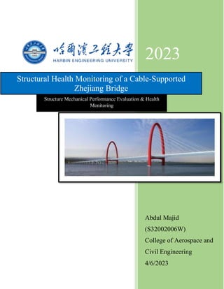
  • 6. 5 based on a comprehensive sensory system and data processing system. Its main objectives are to monitor loading conditions, assess performance, verify design rules, detect damage, and guide inspection and maintenance. SHM system is used to investigate highway loading, railway loading, strong wind characteristics, and temperature effects, and to identify time-varying natural frequencies and modal damping ratio. A long suspension bridge built in a wind-prone region will suffer buffeting-induced vibration which can cause fatigue damage to steel structural members. A systematic framework for assessing buffeting-induced fatigue damage is proposed using the SHM system and integrating wind/structural components with the continuum damage mechanics (CDM)-based fatigue damage assessment method. This study examines the integrated system of structural health monitoring and intelligent management of Zhijiang Bridge in Hangzhou City, China. It illustrates the four functional sub- systems used in a SHM: an information acquisition system (IAS), data management system (DMS), evaluation and decision making system (EDS) and application service system (ASS). This study provides a reference to facilitate the construction of SHM systems for other bridges. 2. Bridge Description Zhijiang Bridge is located in Hangzhou, China, and is a two-arched tower and twin-plane cable- stayed bridge with a combined span of 478 m. The bridge structure employs a half-floated system, with the tower being an arched steel structure with an elliptical curve, the central axis having an elliptical curve, the height of the tower is 90.5 m, the central width of the tower is 44.4 m, and the width of the pylon in the lateral direction is 3.6 m. The pylon exhibits linear variation up and down in the vertical direction, with the width at the top of the tower being 4.0 m and the width at the bottom of the tower being 6.0 m. The beam of the main bridge is a streamlined steel box girder, with the two sides comprising wind fairs and sideways, the height of the beam is 3.5 m, the full width is 41.36 m, and the thickness of the top slab is 16 mm. There were 88 cables in the bridge, which consisted. Figure 1Photograph of Zhijiang Bridge
  • 7. 6 3. Bridge Monitoring System Zhijiang Bridge is a two-arched tower and cable-stayed bridge with the largest span, highest steel arch tower, and widest bridge floor of this type of bridge. It was necessary to build a SHM system to meet the operational management needs, improve the level of prealarm security, enhance the efficiency of maintenance management, and facilitate scientific and effective operational management. The core tasks of the SHM system are to determine the environmental load, structural response, partial damage, and other information, as well as to obtain security state information for the traffic and structure based on a comprehensive assessment of this information, ensuring structural safety and efficient and economic operational decision-making. The integrated system of structural health monitoring and intelligent management used by Zhijiang Bridge comprises four functional sub-systems: IAS, DMS, EDS, and ASS. IAS is a lower level system that includes a data monitoring subsystem and maintenance management subsystem, while DMS and EDS are middle level systems that include a data management subsystem and a structural state evaluation subsystem. ASS is the upper level system that includes a user interface subsystem. Using wired fiber communication and direct inputs, the IAS exchanges data with the DMS according to acquisition rules. The DMS also provides necessary data support for the EDS, as well as providing data queries for the ASS. The structural state evaluation subsystem of the EDS provides analytical results that facilitate decision making and prealarming maintenance management, while the security prealarming subsystem feeds back to the ASS. An SHM system was designed to monitor the structural health, safety, and performance of the bridge. Two categories of phenomena were measured: load-effect monitoring and response monitoring. An anemoscope and temperature sensors were installed to validate wind parameters and provide wind load information. Global dynamic properties were determined to calibrate the bridge theoretical model. Figure 2 shows the integrated system of Zhijiang Bridge uses the DMS and EDS to interface with the Expressway Monitoring Advisory System (EMAS) of Hangzhou City. Monitoring information, evaluation results, maintenance decisions, and warning information related to the bridge can be input into the monitoring center and Traffic Emergency Command Center of Hangzhou City, sharing the monitoring data and decisions generated by the system.
  • 8. 7 Figure 2Overall workflow of the system 3.1 Design and Implementation of the IAS 3.1.1 Sensor Systems The sensor module design of the SHM system used by Zhijiang Bridge includes work environment monitoring, structure spatial deformation monitoring, bridge alignment monitoring, section stress monitoring, fatigue and welding crack monitoring, and vibration monitoring in the steel arch tower and steel box girder, impact force monitoring in the bridge pier, earthquake response monitoring, cable force monitoring, and anchor force monitoring in the steel-concrete joint segment. The numbers of sensors and their layout are shown in Figure 3.
  • 9. 8 Figure 3Layout of sensors on Zhijiang Bridge. Work Environment Monitoring 1) The middle span of Zhijiang Bridge is affected by the wind, so there are monitoring points for wind load, environmental temperature, humidity, rainfall, and visibility. The monitoring instrument is fixed to the bridge floor of the steel box girder on the downstream side of the main span of the main bridge via a stainless steel column located on the outside of a side guardrail. The SHM system installed in the bridge enabled wind data to be analyzed and wind characteristics such as mean wind speed, direction, turbulence components, intensities, integral scales and wind spectra were obtained. A professional meteorological station (Lufft) is used to monitor atmospheric temperature, humidity, visibility, wind speed and direction, and rainfall. Figure 4 and Table 1 show images and technical specifications. Table 1Meteorological station technical specifications. Parameter Technical specifications Wind speed Measurement range: 0–60 m/s; resolution: 0.1 m/s; precision: ±0.3 m/s Wind direction Measurement range: 0–359°; resolution: 1°; measurement accuracy: < ±3° Temperature Measurement range: −20°C to 70°C; measurement accuracy: < ±0.2°C Relative humidity Measurement range: 0–100% RH; measurement accuracy: < ±2% RH Rainfall Measurable raindrop size range: 0.3–5 mm; resolution: 0.01 mm
  • 10. 9 Visibility Measurement range: 10–20000 m; resolution: 0.1 m; precision: +2% Figure 4Meteorological station. 2) The structural components of the main Zhijiang Bridge are steel box girders and steel arch towers. A ventilation and dehumidification system is present inside the steel structure, which can control the temperature and relative humidity inside the steel box girder and steel arch tower. However, in extreme high temperature or extreme high humidity weather conditions, or during sudden power failures, the humidity will increase inside the steel structure, which will affect the durability of the steel structure. Therefore, a temperature and humidity sensor is placed in an appropriate position inside the steel box girders and steel arch towers, which monitors the changes in temperature and humidity. Two sections of steel box girder and four sections of steel arch tower at the junction of steel box girder and steel arch tower have a hygrothermograph. A networked-edition DSR temperature and humidity recorder is used to monitor the temperature and humidity of the steel box girder and steel arch tower, a photograph of which is shown in Figure 5 and the main technical specifications are presented in Table 2. Table 2Hygrothermograph technical specifications. Project Technical specifications Temperature Measurement range: −20°C to 70°C; measurement accuracy: < ±0.2°C Relative humidity Measurement range: 0–100% RH; measurement accuracy: < ±2% RH
  • 11. 10 Figure 5Hygrothermograph 3) The Weigh-in-Motion system is used to monitor vehicle load in real-time and accurately determine axle loads of passing vehicles. This includes calculating the vehicle weight and obtaining license plate numbers of overweight vehicles. The bridge is bidirectional with six lanes, so the system needs to monitor six points in total. WIM stations use two bending path pads and two magnetic loop detectors to measure vehicle weight and axle numbers. TDC Systems (UK) manufactures the Weigh-in-Motion system to monitor traffic load, with the main instrument parameters shown in Table 3. Table 3Weigh-in-Motion system technical specifications. Parameter Technical specifications Speed range 0~180 km/h Traffic counting accuracy ±0.1% Average speed accuracy ±1.5% Gross vehicle weight accuracy ±3% Spatial Structure Deformation Monitoring Finite elements analysis of Zhijiang Bridge showed that the spatial deformation in the top of the steel arch tower and steel box girder in the middle main span was the largest with different load combinations. Therefore, a Global Position System (GPS) is used to monitor the spatial
  • 12. 11 deformation at these sites. Two GPS sensors are positioned at the top of the east and west steel towers, and two sensors are located upstream and downstream of the steel box girder in the middle main span. The same brand of GPS sensor is used to monitor a number of major projects in China, such as Hangzhou Bay Bridge. The main technical specifications of the GPS sensors are shown in Table 4. Table 4Technical specifications of the GPS sensors. Parameter Technical specifications Static long baseline solution precision Horizontal: 3 mm + 0.5 ppm Vertical: 6 mm + 1 ppm Fast static baseline solution precision Horizontal: 5 mm + 0.5 ppm Vertical: 10 mm + 1 ppm Dynamic point baseline solution precision Horizontal: 10 mm + 1 ppm Vertical: 20 mm + 2 ppm Control function Real-time RTK function, with a maximum sampling frequency of ≥5 Hz Transmission performance Real-time automatic collection, 24 h without exception Working environment Receiver and terminal: −20°C to 50°C; antenna: −40°C to 50°C Figure 6GPS sensor.
  • 13. 12 Figure 7Wind and Structural Monitoring Bridge Alignment Monitoring The positions with the maximum variation in the displacement of the main beam with various load combinations are the middle main span and the middle side span, and the variation in the displacement of the quarter-point of the main span is also high. Subsidence points on the pier tops are also monitored in addition to monitoring the alignment of the main bridge network. The east approach of Zhijiang Bridge is a continuous beam of 60 + 11 86 + 60 m, and a three-span structure of the main bridge on the Dongfei navigation channel is used as the key monitoring point. A hydrostatic level gauge is used for alignment monitoring, and its technical specification is shown in Table 5. Table 5Technical specifications of the hydrostatic level gauge. Parameter Technical specifications Measurement range ±300 mm Measurement accuracy ±0.5% FS Sensitivity 0.05 FS Operating temperature −20°C to 80°C
  • 14. 13 Protection class IP67 Figure 8Hydrostatic level gauge Stress, Fatigue, and Welding Crack Monitoring The high-stress sections on the steel box girders of double-towered, cable-stayed bridges are generally present in the middle of each span, the juncture of a box girder and a cable tower, and the load-bearing position. The high-stress sections of the cable tower are generally present at the bottom of the cable tower and the juncture of the cable tower and steel box girder. The sections in the middle of each span of the main bridge, the quarter-point of the main span, and the pier tops are used to monitor the steel box girder stress, fatigue, and welding cracks. The sections at T0, T1, and T7, the top of the tower, and the steel horizontal beam of the steel arch tower were selected to monitor stress and welding cracks in the steel arch tower.
  • 15. 14 Figure 9Stress and fatigue monitoring points on the box girder. Figure 10Welding crack monitoring points on the box girder.
  • 16. 15 Figure 11Stress and fatigue monitoring points on the steel tower. The stress on the box girder top slab in the lateral direction is relatively high at the longitudinal diaphragm and that in the longitudinal direction is relatively high at the web. Monitoring points were selected based on the layout of the bridge to ensure continuous monitoring. Strain gauges are used to monitor Strain, the number of sensors in each monitoring position is shown in Table 6 and the specifications are shown in Table 7. Table 6Strain sensor arrangement. Monitoring position Number Midsection of the main span 12 1/4, 3/4 section of main span 24 Midsection of the side span 24 Section of steel box girder at each pier top 16 T0, T1, and T7 and top section of steel arch tower 56 Section of the lateral steel beam 16 Section of the approach 100
  • 17. 16 Table 7Technical specifications of the strain sensor. Parameter Technical specifications Measurement range ±2000 μ ε Resolution ±1 μ ε Measurement accuracy ±2-3 μ ε Strain sensitivity 1.18–1.22 pm/μ ε Figure 12Strain gauges Structural Temperature Monitoring Structural temperature monitoring is used to facilitate temperature compensation during stress monitoring and determine the temperature ranges of key sections. Optical fiber grating temperature sensors are used, with a measurement range of 20°C to 70°C and a precision of less than 0.2°C. The positions and number of monitoring points are shown in Table 8. Temperature variations cause long suspension bridges to expand and contract in the longitudinal direction and bend in the vertical plane, causing large forces to develop. This section introduces temperature effects on displacement responses and provides a basis for real-time monitoring. Temperature sensors measure ambient and bridge member temperatures along the bridge longitudinal axis. Table 8Position and number of temperature monitoring points. Monitoring position Sensor type Number Midsection of the main span Temperature sensor 2 1/4, 3/4 section of main span Temperature sensor 4 Midsection of the side span Temperature sensor 4 Section of the steel box girder at each pier top Temperature sensor 8
  • 18. 17 T0, T1, and T7, and top section of steel arch tower Temperature sensor 32 Section of the lateral steel beam Temperature sensor 4 Section of the approach Temperature sensor 14 Structural Vibration Monitoring Structural vibration monitoring involves monitoring vibrations in the steel arch tower and the steel box girder, as well as the impact force on the bridge pier and earthquake responses. Vibration sensors are positioned in the middle of each span, the quarter-point of the main span, and the pier tops on both sides of the main span of the steel box girder. To monitor the impact force on the bridge pier, the top of the pile cap of each navigable span is used as a vibration monitoring point. Additionally, a vertical vibration sensor is placed at the same position to monitor the impact force and earthquake responses. The vibration sensor is shown in Figure 12 and the sensor layout is shown in Table 9. Cable-supported bridges are susceptible to vibration caused by wind, rain and support motion. This can cause undue stresses and fatigue in the cables and in the connections with bridge deck and towers, and can lead to public confidence in the bridges. To suppress harmful vibration, passive viscous and viscoelastic dampers have been used. Table 9Layout of the vibration sensors. Monitoring position Sensor type Number T0, T7, and top section of tower Vibration sensor 10 Top of the pile cap of each navigable span Vibration sensor 8 1/4, 1/2 section of the main-span, 1/2 section of the side-span, and section of the pier top Vibration sensor 8
  • 19. 18 Figure 13Vibration sensor Acceleration sensors are used to monitor vibrations, impact forces, and earthquake responses. They have a measurement range of 2 g, a frequency response of zero to 100 Hz, a dynamic range of >120 dB, and a working temperature range of 20°C to 80°C. Cable Force Monitoring The cable is the main component of a cable-stayed bridge, which transfers the weight of the main girder and the live load on the deck to the main tower. It is important to enhance cable force monitoring to evaluate the working status of the cable and analyze the stress state of a cable-stayed bridge. Amplitude monitoring must form the basis of cable tension monitoring, and cables with the maximum stress under different load combinations and the maximum variation in stress under live loadings are used for cable tension monitoring. Acceleration sensors are used to monitor the tension of stayed cables, with a measurement range of 10 g, a frequency response of zero to 100 Hz, a dynamic range of >80 dB, and a work temperature of 20°C to 80°C. The positions and numbers of sensors are shown in Table 10. Table 10Positions and numbers of acceleration sensors. Monitoring positions Number 1, 1, 11# cables in the side-spans of the east and west sides 12 1, 7, 11# cables in the main-span of the east and west sides 12
  • 20. 19 Figure 14Acceleration sensor. Anchor Force Monitoring The reliability of the juncture of the steel tower, concrete bearing, and foundation is key to guaranteeing the structural safety of the whole bridge. This is because the static disequilibrium of the steel tower in a horizontal direction, the dynamic response to wind load and earthquake, and the connection between the steel tower and the bearing would be damaged by a major horizontal force and bending moment. An anchor is used to connect the main tower and the cap of Zhijiang Bridge, and the pretightening force of the anchor directly reflects the operational status of the juncture segment of steel and concrete. It is necessary to monitor the variation in the anchor force in real-time. To guarantee the stability and durability of anchor force monitoring at the juncture of steel and concrete, fiber grating strain sensors are used and the total number of monitoring points is 32. 3.1.2 Data Acquisition and Transmission Module The data acquisition and transmission module is composed of an acquisition facility, transmission facility, and data preprocessing and temporary storage facility. The data transmission modes between the sensor and acquisition facility and the low-level instrument are wireless and wired. To improve the stability of the data transmission, wired data transmission is used between the sensor and acquisition facility and the low-level instrument. Two low-level instruments are positioned in the steel box girder section at the junctures of two steel arch towers and the steel box girders on the main bridge. Data is transferred between the low-level instruments and the monitoring center via an embedded optical communication cable. Figure 14 shows the function flow during data acquisition and transmission. All of the sensors are connected via an anti-interference shielding line and the corresponding acquisition facility. The acquisition facilities for stress, temperature, and vibration are integrated into the steel box girder
  • 21. 20 section under the two main towers of the bridge. To ensure highly synchronized vibration acquisition, the GPS clock is used for clock synchronization between the two acquisition stations for the stress, temperature, and vibration sensors. The transmission distance is longer than 200 m, so the GPS clock is used for clock synchronization between the two acquisition stations for the stress, temperature, and vibration sensors. Figure 15Flowchart of data acquisition and transmission. 3.1.3 Software System The design of the system software must meet the needs for data acquisition and transmission control, maintenance checking data management, data comprehensive management, data analysis and status evaluation, maintenance decision and safety prealarming, and user management. The software is divided into data acquisition and transmission software, maintenance management software, center database software, structural status evaluation software, maintenance decision and safety prealarming software, user interface software, and other components. The data acquisition and transmission software includes an acquisition instruction module, parameter setting module, data preprocessing module, abnormal event log module, software self-repair module, graph display module, and other components. The system runs on a network and some examples of the results obtained are shown in Figures 15, 16, 17, 18, and 19.
  • 22. 21 Figure 16External environment of the bridge. Figure 17Vibration of 4# tower and T7 box girder.
  • 23. 22 Figure 18Displacement changes in the box girder. Figure 19Tower shift. Figure 20Cable force.
  • 24. 23 3.2 Design and Implementation of the DMS The SHM system of Zhijiang Bridge uses a data management subsystem to acquire data from the health monitoring subsystem, maintain data from the maintenance management subsystem, monitor data from the road floor status, and collect, file, inquire, store, and manage monitored prestress data. Figure 21Function and composition of the DMS. 3.3 Design and Implementation of the EDS The structural status evaluation subsystem is the core of the integrated system. It executes various operations such as calculation analysis, statistics, historical alignment, analysis and trend forecasting, and fetches key indices that reflect variations in the structural status. The overall data is integrated to facilitate a comprehensive evaluation of the status of the bridge structure and its key components. The structural status evaluation subsystem is divided into two modules: data processing and status evaluation, which perform the same functions. 1) The data processing module is responsible for filtering, classification, collection, and statistical analysis of the data, and for fetching the key indices. 2) The status evaluation module is responsible for real-time analysis and evaluating the structural status. 3.3.1 Data Processing Module The volume of bridge monitoring data is massive, so they must be finely analyzed in detail to obtain useful key information. The functions of the data processing module are as follows. 1) The original test values from each sensor are integrated to obtain the primary status of the bridge health monitoring data. 2) Filtering, classification, collection, and statistical analyses of the monitoring data are performed to obtain an eigenvalue database of the monitoring data. 3) Based on the monitoring results and comparisons with the values in the design document, the experimental bridge loading values, modified values from simulation calculations, and
  • 25. 24 the extreme values during the operational process, the variations in the rates of the values that reflect the structural status can be obtained, which can be analyzed to identify trends using mathematical model fitting. 4) The degree of deviation and rate of development are calculated based on comparisons with the threshold values of all the bridge safety prealarming levels. 3.3.2 Status Evaluation Module The status evaluation module is responsible for damage identification and status evaluation. It identifies the position, degree, and rate of development of structural damage based on abnormal data, then evaluates the effects of damage by combining bridge maintenance checking data with scientific monitoring data. If the user state exceeds the critical condition, the evaluation information is passed to the maintenance decision and safety prealarming subsystem. The flow during status evaluation is shown in Figure 21. Figure 22Flowchart during bridge condition evaluation. Methods such as module modification, structural fatigue analysis, primary fingerprint comparison, trends analysis, model state analysis, parameter identification, and reliability evaluation are used to localize, quantify, and identify damage by monitoring trends and evaluating their effects. These methods satisfy the structural type, materials, and work environment of Zhijiang Bridge. 3.4 Design and Implementation of the ASS The ASS used by the SHM system of Zhijiang Bridge is an interactive system for bridge maintenance management users. It provides functions such as monitoring point information display, monitoring results graphical display, report management, background management, and user management. The comprehensive management software implemented in the system provides many functions, such as information management and querying of monitoring points, monitoring and maintenance of data queries, graphical displays, state evaluation result querying, report
  • 26. 25 management and inquiry, prealarming information management and inquiry, background management, and user management. 4. Conclusions The core problems and final aims of SHM systems for cable-stayed bridges are damage identification, module modification, structural safety evaluation, and maintenance decision making. This study used the integrated system of structural health monitoring and intelligent management of Zhijiang Bridge as an example to provide a detailed explanation of the components and model functions employed by a large-scale bridge SHM system. This SHM system generates time-specific status information such as bridge vibrations, providing data support for bridge maintenance and decision making. The application of SHM systems to large-scale Chinese bridges is in the early stage, and new technology and new methods will be beneficial to improving SHM systems. Wireless communication technology such as microwaves may be an important method in SHM system networks for bridge structures, which could be applied broadly to health monitoring and the measurement of bridge structures. The use of advanced SHM systems allows continuous monitoring and effective management of large civil engineering structures, such as long span bridges, high-rise buildings, underground tunnels, high speed railway lines and buried water mains. These monitoring systems include the wind and SHM system, wireless sensing networks, acoustic emissions and fiber optic sensing systems. Local monitoring techniques are more likely to locate structural damage in local regions, while global monitoring methods should be combined with the use of local monitoring techniques to obtain a better understanding of structural damage. When long-term monitoring data of both structural responses and operational factors (e.g. loads, temperature, wind, etc.) are available, it is possible to quantitatively assess the current condition and even predict the future performance of the existing civil engineering structures using the continuous measurements. For civil engineering structures, continuous structural monitoring requires the use of robust sensors that can withstand the damaging effects of the aggressive environments. These sensors are expected to operate for the service life of the structures, which is often over 50 years. The density of sensors on a civil structure should be sufficient to make an effective global monitoring approach on a large scale. The structural monitoring systems need to be inexpensive and easy to deploy, so that the systems can be attached to existing civil structures with little effort. Further works on SHM of large civil engineering structures are needed, such as advanced sensing systems with improved and optimized placement of networkable sensors, reliable wireless sensors and data transmission systems, advanced signal processing techniques, software and hardware integration, effective methods for data interpretations and damage feature extractions, predictive damage model for a structure and its components, and reliability based and monitoring informed optimal maintenance strategies. Sensors are essential elements of structural health monitoring systems. Optical fiber sensors provide superior structural health monitoring capabilities for civil structures. The primary advantage of optical fiber sensors is their geometric conformity and capability for sensing of a variety of perturbations. This article provides a summary of basic principles pertaining to the
  • 27. 26 structural health monitoring of civil engineering structures with optical fiber sensors. It is possible to design optical fiber systems for measurements of myriads of perturbations, including strain, cracks, deformations, accelerations, cable dynamics, etc. Other issues include protection of fibers against damage by design of proper sensor packaging systems. 5. Future Trends Science and technology are driving the development of SHM analysis for condition assessment and damage detection of cables. However, key challenges remain for further application, such as the difficulty of estimating cable damage due to health condition and uncertainties such as traffic. Future trends include data acquisition, development of new monitoring equipment, and recognition of uncertainties in real bridges. These targets affect the stability of stay cables in the long run. SHM is becoming increasingly important in civil infrastructure, but there is a lack of understanding of the needs for a viable system. To address this, steps are suggested to design and implement vibration-based health monitoring systems for highway bridges: 1) The target structure should be surveyed and studied carefully to establish its baseline structural and response characteristics. Dynamic responses should be measured at appropriate locations on the structure during its typical operational conditions. Mobile instrumentation should be used to investigate as many locations as possible. Acceleration is usually the preferred type of measurement in terms of dynamic response. The magnitude and frequency content of the acceleration collected during typical operation conditions will dictate the type and parameters of the sensors to be used in the health monitoring system. Capacitive or resistive accelerometers are more suitable for such types of applications. In cases where the health monitoring system is expected to collect data during extreme events, predicted response based on finite element models of the structure and past knowledge of the excitation due to extreme events can be used in place of this data. 2) Modal analysis should be performed to identify the initial modal parameters. Operational modal analysis can be used for identification when responses caused by ambient excitation are used. Forced excitation sources such as impact hammers or electromagnetic shakers can also be utilized. The characteristics of the identified dominant modes should be studied carefully to determine the number and location of sensors needed to effectively characterize them. The minimum number of sensors needed to successfully identify a mode can be determined by Shannon's sampling theorem, but the density of the sensor network will also be determined by the intended spatial resolution of the damage localization. 3) The data acquisition, transmission and archiving system must be designed to accommodate the type, number and location of the sensors in the sensing system. The sampling rate should be determined by the frequency range of interest identified in the second step. The Nyquist frequency should be at least two times the highest frequency of interest. The amount of data collected is directly proportional to the sample rate and the number of sensors or channels simultaneously measured. For large civil engineering structures, tens of thousands of samples may be recorded every second. 4) A baseline finite element model should be updated using modal parameters identified using sensitivity analysis. The model can represent the pristine state of the structure or its state
  • 28. 27 at a selected point in time, depending on the modal parameter used. The model updating process can also be augmented by static response measured during load tests. 5) Operational modal analysis can be used to extract modal parameters from measured structural response using algorithms. 6) Damage localization should be performed using modal parameters and techniques, and the baseline finite element model should be updated to record changes in the actual structure. 7) The SHM system can be used to accurately estimate the structural capacity and remaining life of a structure, making it more effective. Operational modal analysis is a mature technology, but there is still much work to be done to verify assumptions, evaluate statistical properties, and compare methods. Future research should lead to the integration of a statistical framework into the damage identification process, with operational variability quantified and confidence bounds given, using extreme value statistics and Bayesian statistical models. Finite element model updating is an efficient technique for damage diagnostics, but there are challenges such as non-uniqueness, ill-conditioning, and numerical convergence. Techniques such as dense sensor networks, dynamic properties, and globally robust optimization algorithms can help solve or alleviate these issues. A new multi-level structural health monitoring system integrating global- and local-level diagnostics is needed to satisfy all end users' requirements. Mission-tailored sensor technologies such as piezoelectric and fiber-optic sensors with wireless communication capabilities are essential to reduce system cost and improve efficiency.
  • 29. 28 References [1] L. I. Hong-Nan, Y. I. Ting-Hua, R. E. N. Liang, L. I. Dong-Sheng, and H. U. O. Lin-Shen, “Reviews on innovations and applications in structural health monitoring for infrastructures,” Monitoring and Maintenance, vol. 1, no. 1, pp. 1–45, 2014. [2] M. Abe, Y. Fujino, M. Yanagihara, and M. Sato, “Monitoring of Hakucho Suspension Bridge by ambient vibration measurement,” in Nondestructive Evaluation of Highways , Utilities, and Pipelines IV, Proceedings of SPIE, pp. 237–244, Newport Beach, Calif, USA, March 2000. [3] M. Çelebi, R. Purvis, B. Hartnagel et al., “Seismic instrumentation of the Bill Emerson Memorial Mississippi River Bridge at Cape Girardeau (MO): a cooperative effort,” in Proceedings of the 4th International Seismic Highway Conference, Memphis, Tenn, USA, 2004. [4] S. H. Sim, J. Li, H. Jo et al., “Wireless smart sensor network for automated monitoring of cable tension,” Smart Materials and Structures, vol. 23, no. 2, 2014. [5] K. Y. Wong, “Instrumentation and health monitoring of cable-supported bridges,” Structural Control and Health Monitoring, vol. 11, no. 2, pp. 91–124, 2004. [6] S. S. Kessler, S. M. Spearing, and C. Soutis, “Damage detection in composite materials using lamb wave methods,” in Proceedings of the American Society for Composites, Blacksburg, Va, USA, September 2001. [7] J. Ma and D. Pines, “The concept of dereverberation and its application to damage detection in civil structures,” in 7th International Symposium on Smart Structures and Materials, Proceedings of SPIE, March 2000. [8] F. K. Chang, “Built-in diagnostic for structural health monitoring,” in Proceedings of the Grantees Meeting, USJapan Urban Earthquake Disaster Mitigation Research Initiative, Sonoma, Calif, USA, 1999. [9] M. W. Lin, A. O. Abatan, and Y. Zhou, “Transverse shear response monitoring of concrete cylinder using embedded high-sensitivity ETDR sensor,” in Smart Structures and Materials 2000: Smart Systems for Bridges, Structures, and Highways, vol. 3988 of Proceedings of SPIE, pp. 319–328, Newport Beach, Calif, USA, March 2000. [10] T.-H. Yi, H.-N. Li, and M. Gu, “Optimal sensor placement for structural health monitoring based on multiple optimization strategies,” The Structural Design of Tall and Special Buildings, vol. 20, no. 7, pp. 881–900, 2011. [11] T.-H. Yi, H.-N. Li, and M. Gu, “Full-scale measurement of dynamic response of a suspension bridge subjected to environmental loads using GPS technology,” Science China: Technological Sciences, vol. 53, no. 2, pp. 469–479, 2010. [12] T.-H. Yi, H.-N. Li, and M. Gu, “Experimental assessment of high-rate GPS receivers for deformation monitoring of bridge,” Measurement, vol. 46, no. 1, pp. 420–432, 2013. [13] J. P. Lynch, Y. Wang, K. J. Loh, J. H. Yi, and C. B. Yun, “Performance monitoring of the geumdang bridge using a dense network of high-resolution wireless sensors,” Smart Materials and Structures, vol. 15, no. 6, article 008, pp. 1561–1575, 2006. [14] T. Nagayama and B. F. Spencer Jr., “Structural health monitoring using smart sensors,” Newmark Structural Engineering Laboratory Report Series 001, 2007, http://hdl.handle.net/2142/3521.
  • 30. 29 [15] S. Kim, S. Pakzad, D. Culler et al., “Health monitoring of civil infrastructures using wireless sensor networks,” in Proceedings of the 6th International Symposium on Information Processing in Sensor Networks (IPSN '07), pp. 254–263, April 2007. [16] S. Jang, J. A. Rice, J. Li, H. Jo, B. F. Spencer Jr., and Z. Wang, “Structural monitoring of a historic truss bridge using a wireless sensor network,” in Proceedings of the Asia-Pacific Workshop on Structural Health Monitoring, 2009.