
Recommended
More Related Content
What's hot
What's hot (20)
Similar to DESIGN AND ANALYSIS OF CONVERGENT DIVERGENT NOZZLE USING CFD
Similar to DESIGN AND ANALYSIS OF CONVERGENT DIVERGENT NOZZLE USING CFD (20)
Recently uploaded
Recently uploaded (20)
DESIGN AND ANALYSIS OF CONVERGENT DIVERGENT NOZZLE USING CFD
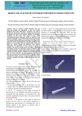
- 1. IN(Online): 4142-3453 February 2017 Issue DESIGNANDANALYSISOFCONVERGENTDIVERGENT NOZZLE USINGCFD Rama Thulasi1 , N. Jashuva 2 1 M.Tech (MECH)., Dept of Mech., Global College Of Engineering and Technology, Kadapa, Andhra Pradesh. 2 Assistant Professor, Dept of Mech, Global College Of Engineering and Technology, Kadapa, Andhra Pradesh. Abstract- CFD is a branch of fluid mechanics that uses numerical methods and algorithms to solve and analyze problems that involve fluid flows. Computers are used to perform the calculations required to simulate the interaction of liquids and gases with surfaces defined by boundary conditions. In this thesis, CFD analysis of flow within Convergent-Divergent supersonic nozzle of different cross sections rectangular, square and circular has been performed. The analysis has been performed according to the shape of the supersonic nozzle and keeping the same input conditions. Our objective is to investigate the best suited nozzle which gives high exit velocity among the different cross sections considered. The application of these nozzles is mainly in torpedos. The work is carried out in two stages: 1.Modeling and analysis of flow for supersonic nozzles of different cross sections.2.Prediction of best suited nozzle among the nozzles considered. In this, initially modeling of the nozzles has been done in CATIA and later on mesh generation and analysis have been carried out in ANSYS FLUENT 14.5 and various contours like velocity, pressure, temperature have been taken and their variation according to different nozzles has been studied. 1.INTRODUCTION A nozzle is a device that is used to increase the velocity of a flowing fluid. It does this by reducing the pressure. CONVERGENT-DIVERGENT nozzle is designed for attaining speeds that are greater than speed of sound. the design of this nozzle came from the area-velocity relation (dA/dV)=-(A/V)(1-M^2) M is the Mach number ( which means ratio of local speed of flow to the local speed of sound) A is area and V is velocity The following information can be derived from the area- velocity relation - 1. For incompressible flow limit, i.e. for M tends to zero, AV = constant. This is the famous volume conservation equation or continuity equation for incompressible flow. 2. For M < 1, a decrease in area results in increase of velocity and vice vera. Therefore, the velocity increases in a convergent duct and decreases in a Divergent duct. This result for compressible subsonic flows is the same as that for incompressible flow. 3. For M > 1, an increase in area results in increase of velocity and vice versa, i.e. the velocity increases in a divergent duct and decreases in a convergent duct. This is directly opposite to the behavior of subsonic flow in divergent and convergent ducts. 4. For M = 1, dA/A = 0, which implies that the location where the Mach number is unity, the area of the passage is either minimum or maximum. We can easily show that the minimum in area is the only physically realistic solution. One important point is that to attain supersonic speeds we have to maintain favorable pressure ratios across the nozzle. Taking the rectangular bent nozzle as reference and keeping the inlet, throat and exit areas and the axis length constant, three dimensional rectangular, square and circular straight nozzles geometries were generated. 1.Square Shape: 2.Circular Shape:
- 2. IN(Online): 4142-3453 February 2017 Issue 3.Rectangular Shape II LITERATURE SURVEY JET ENGINE A jet engine is a system for turning fuel into thrust (ahead motion). The thrust is produced with the aid of action and reaction a bit of physics additionally known as Newton’s 0.33 law of movement The pressure (movement) of the exhaust gases pushing backward produces an same and opposite force (response) known as thrust that powers the automobile ahead. exactly the same principle pushes a skateboard ahead when you kick backward along with your foot. In a jet engine, it's the exhaust gas that gives the "kick". Jet engine designs are regularly modified for non-aircraft programs, as business gas turbines. these are utilized in electric electricity generation, for powering water, natural gasoline, or oil pumps, and supplying propulsion for ships and locomotives. industrial gasoline turbines can create as much as 50,000 shaft horsepower. Precept of jet engine The gasoline turbine operates on the Brayton cycle in which the working fluid is a non-stop drift of air ingested into the engine’s inlet. The air is first compressed by way of a compressor (duct chamber) to a strain ratio of normally 10 to forty instances the strain of the inlet airstream. It then flows into a combustion chamber, where a steady move of the hydrocarbon gas, in the shape of liquid spray droplets and vapor or both, is added and burned at approximately consistent strain. This offers rise to a continuous stream of high-stress combustion products whose common temperature is normally from 980 to at least one,540 °C or higher. This movement of gases flows via a exhaust nozzle, that is connected by means of a compressor and combustion chamber which extracts strength from the gasoline circulation to produce thrust. due to the fact heat has been brought to the working fluid at excessive pressure, the gasoline move that exits nozzle is excessive. The primary JET ENGINE-quick history OF EARLY JET ENGINES SIR ISAAC NEWTON within the 18th century changed into the first to theorize that a rearward-channeled explosion could propel a gadget forward at a splendid price of speed. This concept changed into primarily based on his third law of motion. As the hot air blasts backwards via the nozzle the aircraft moves forward. HENRI GIFFORD constructed an airship which turned into powered by way of the primary aircraft engine, a 3-horse electricity steam engine. It changed into very heavy, too heavy to fly. In 1874, FELIX DE TEMPLE built a monoplane that flew only a short hop down a hill with the assist of a coal fired steam engine. OTTO DAIMLER, within the overdue 1800's invented the first fuel engine. In 1894, American HIRAM MAXIM attempted to strength his triple biplane with two coal fired steam engines. It best flew for some seconds. The early steam engines had been powered by way of heated coal and have been normally an awful lot too heavy for flight. American SAMUEL LANGLEY made model airplanes that have been powered by way of steam engines. In 1896, he was successful in flying an unmanned plane with a steam-powered engine, referred to as the Aerodrome. It flew approximately 1 mile earlier than it ran out of steam. He then tried to construct a full sized plane, the Aerodrome A, with a gasoline powered engine. In 1903, it crashed at once after being launched from a residence boat. STYLES OF JET ENGINES There are a huge range of different kinds of jet engines, all of which acquire ahead thrust from the precept of jet propulsion. reaching a excessive propulsive efficiency for a jet engine is dependent on designing it in order that the exiting jet pace is not significantly in excess of the flight speed. at the same time, the amount of thrust generated is proportional to that very identical speed extra that have to be minimized. This set of restrictive requirements has caused the evolution of a big quantity of specialized variations of the fundamental turbojet engine, every tailored to reap a balance of suitable gas efficiency, low weight, and compact size for responsibility in some band of the flight pace altitude challenge spectrum. There are two fundamental fashionable features characteristic of all the one-of-a-kind engine sorts, however. First, so as to obtain a excessive propulsive performance, the jet pace, or the rate of the fuel circulate exiting the propulsion, is matched to the flight pace of the plane slow aircraft have engines with low jet velocities and fast aircraft have engines with excessive jet velocities. 2nd, because of designing the jet velocity to match the flight pace, the size of the propulsion varies inversely with the flight speed of the aircraft slow plane have very large propulsors, as, as an instance, the helicopter rotor and the relative length of the propulsor decreases with growing design flight pace turboprop propellers are fantastically small and turbofan enthusiasts even smaller. The primary idea of the turbojet engine is easy. Air taken in from a gap within the the front of the engine is compressed to a few to 12 instances its unique strain in compressor. gasoline is added to the air and burned in a combustion chamber to raise the temperature of the fluid aggregate to about 1,a hundred°F to at least one,three hundred° F. The resulting hot air is handed via a turbine, which drives the compressor. If the turbine and compressor are green, the pressure on the turbine discharge can be nearly two times the atmospheric strain, and this excess stress is sent to the nozzle to provide a excessive- pace flow of gas which produces a thrust. full-size will increase in thrust can be received by way of employing an afterburner. it's miles a second combustion chamber placed after the turbine and earlier than the nozzle. tremendous increases in thrust may be received by way of using an afterburner. it is a 2nd combustion chamber placed after the turbine and before the nozzle. The afterburner will increase the temperature of the gasoline in advance of the nozzle. The end result of this increase in temperature is an growth of about 40 percent in thrust at takeoff and a much larger percent at excessive speeds once the aircraft is inside
- 3. IN(Online): 4142-3453 February 2017 Issue the air. Fig 4: Turbojet engine A turbofan engine has a big fan on the front, which sucks in air. most of the air flows around the out of doors of the engine, making it quieter and giving greater thrust at low speeds. maximum of state-of-the-art airliners are powered by means of turbofans. In a turbojet all the air getting into the intake passes via the gasoline generator, which is composed of the compressor, combustion chamber, and turbine. In a turbofan engine simplest a portion of the incoming air goes into the combustion chamber. The remainder passes thru a fan, or low-pressure compressor, and is ejected directly as a "bloodless" jet or combined with the gas-generator exhaust to produce a "hot" jet. The objective of this type of bypass system is to boom thrust without growing gas consumption. It achieves this with the aid of increasing the entire air-mass drift and lowering the rate within the identical general strength deliver. A turboprop engine is a jet engine connected to a propeller. The turbine on the again is became by using the new gases, and this turns a shaft that drives the propeller. a few small airliners and transport plane are powered by means of turboprops. like the turbojet, the turboprop engine includes a compressor, combustion chamber, and turbine, the air and gasoline pressure is used to run the turbine, which then creates strength to drive the compressor. as compared with a turbojet engine, the turboprop has better propulsion efficiency at flight speeds below approximately 500 miles per hour. current turboprop engines are ready with propellers that have a smaller diameter but a bigger range of blades for efficient operation at a great deal better flight speeds. to house the higher flight speeds, the blades are scimitar-shaped with swept-returned main edges at the blade tips. Engines providing such propellers are called prop fanatics. Max Mueller designed the first turboprop engine that went into production in 1942. Fig 5: Turbo prop engine A ram jet engine is a tool from which beneficial thrust may be obtained through growing a pace difference between the atmosphere getting into the ram jet body and the identical amount of air leaving the ram jet body. This speed distinction among entrance and go out air is achieved via the addition of heat to that part of the airstream flowing thru the ram jet frame. Ramjets can not produce thrust at zero airspeed; they can not move an aircraft from a standstill. A ramjet powered car, consequently, calls for an assisted take-off like a rocket assist to accelerate it to a pace wherein it begins to supply thrust. Ramjets work most efficiently at supersonic speeds around Mach 3 (2,284 mph; 3,675 km/h). This sort of engine can function as much as speeds of Mach 6 (2,041.7 m/s; 7,350 km/h). they have got also been used successfully, although now not efficiently, as tip jets on the stop of helicopter rotors. Ramjets haven't any moving elements just like a valve less pulsejet but they perform with non-stop combustion in place of the collection of explosions that supply a pulsejet its feature noise. Fig 6: Ramjet engine III. SHOCKWAVES Whilst some thing reasons a noise, together with a door lamming or a firecracker popping, it causes a pressure wave to transport via the air, whilst this wave reaches us our ears translate the sudden pressure change into the sound we listen. The stress wave is honestly just air molecules bumping in opposition to every different. The molecules normally simply flow around randomly, moving this manner and that. while the firecracker pops it releases excessive stress gasses that rush outward, pushing in opposition to the air molecules. these molecules in flip circulate outward and encounter others, pushing them along to come upon yet more air molecules. think of a bunch of balls lined up on a pool table. The cue ball moves the first, inflicting it to transport and strike the second. while it does the electricity of motion is transferred to the second ball and the primary ball stops. Likewise, the second ball moves the third, transfers power to it, and forestalls. on this way the electricity passes from one ball to the alternative, and this energy "wave" flows down the road of balls from the primary to the closing. despite the fact that the gap from the primary to closing ball can be high-quality, not one of the individual balls movements very some distance. This is how the pressure wave moves through the air, passing from molecule to molecule. The wave is simply quite a few
- 4. IN(Online): 4142-3453 February 2017 Issue molecules that are no longer shifting randomly, but are all shifting within the identical direction on the identical time till they stumble upon every other air molecule and pass electricity to it. After the wave passes the air molecules cross returned to randomly bumping into every other. As an item actions via the air it pushes apart the air in its route. The transferring air forms a stress wave that moves outward at the velocity of sound. in the image beneath the arrow categorised "pace of sound" represents the gap sound travels at some point of the time of flight of the missiles. Fig 7: Object moves through the air The missile at the left is moving at 1/2 the rate of sound (Mach zero.five). The stress waves created as it movements via the ecosystem are transferring twice as rapid as the missile and use up in all instructions. In all cases the stress waves race in advance of the missile. every semicircle suggests how some distance the sound wave has traveled since the missile surpassed the numbered positions. notice that the space between waves is shorter in front of the missile than off to the aspect of the missile - the waves are compressed ahead of the missile. but, they do not overlap to generate a shock wave. in the center photograph the missile is moving at the speed of sound. The pressure waves make bigger outward at the speed of sound however they can not pass beforehand of the missile. on the main tip of the missile all waves are compressed so that they overlap, however they use up commonly some other place so a surprise wave is not propagated. within the proper hand image the missile is moving quicker than the speed of sound. The strain wave can't move as speedy as the missile so the missile races beforehand of the strain waves. consequently all waves moving outward from the missile's course combine to create a excessive pressure conical "surprise wave" emanating from the nose of the missile, moving outward thru the air at the velocity of sound, like the wake of a ship moving thru water. whilst this surprise wave reaches our ears we hear a "sonic increase." Simple Ramjets It’s far this supersonic surprise wave that is essential to ramjet air consumption functioning, and it turned into the purpose of main complications within the layout of ramjets that could work reliably. it's miles critical to understand that the air molecules in this wave are shifting at the speed of sound, and no faster. The handiest air consumption design is only a hole tube with a circular starting - a pipe. consider a pipe fixed to a supersonic plane or rocket. whilst the pipe is propelled via the air at supersonic speeds the threshold of the opening pushes air molecules out of the manner, forming a shock wave. at the out of doors fringe of the pipe the surprise wave actions outwardly similar to it does around the nose of a supersonic bullet. but, at the inside of the tube the surprise waves from all around the starting converge, as proven by way of the dashed strains. The air molecules moving far from the internal fringe of the outlet run into different molecules moving inward and the stress wave can move no farther. pressure builds up at the back of the shock wave, compressing the air within the tube and slowing the fee at which it flows thru the tube. Fig 8: Shock waves in simple ramjet Now we want to reconsider the relative motions of the tube and the atmosphere. it's far the tube that is shifting faster than the speed of sound, and the air is standing nonetheless. however, the idea of relativity permits us to consider the situation as if the tube become status still and the air was rushing by using at supersonic speeds. As stress rises in the tube air temperature also rises. for the reason that inner walls of the tube save you outward growth of the air in the tube, and the air speeding in the the front prevents get away that way, the hot high pressure gasses can break out most effective from the rear wherein they extend unexpectedly and return to the temperature and pressure of the encircling air. however, this occurs handiest while the tube is shifting through the air very unexpectedly. whilst the new gasses get away at the rear of the tube they may be accelerated as the stress drops. you see the same component whilst water escapes via the quit of your garden hose. The better the water stress inside the hose the faster the water flows from the hose. The higher the stress in the ramjet tube, the quicker the gasses break out on the rear. because the gasses are heated as they may be compressed into the tube, the stress increases even more and that they get away the rear even quicker.
- 5. IN(Online): 4142-3453 February 2017 Issue IV. RESULTS Fig 21: High pressure in combustion chamber Fig 37: Meshed model of rectangular shaped convergent- divergent nozzle Fig 38: Pressure distribution on rectangular shaped convergent-divergent nozzle Fig 39: Velocity distribution on rectangular shaped convergent-divergent nozzle V.CONCLUSION After successfully completing this simulation of a layout created, the decisions have been subsequently restricted into the following factors. FLUENT evaluation has been done on Convergent- Divergent nozzles of different pass sections like square, square and rectangle for Ram Jet Engine by way of using ANSYS 14.5. In parent 31, 35 and 39 speed distribution of round, square and rectangular formed nozzles are shown respectively. As the speed and mass go with the flow fee of air will increase earlier than the diffuser the speed of the jet also will increase It's miles sincerely visible the rate is increasing along with the duration of the nozzle. Because of stunning within the nozzle, the speed reduced for some time however later started out to growth because the fluid accelerated via the divergent component. Stress gradually reduced along the duration of the nozzle except a moderate upward thrust for the duration of the stunning. however, the rise changed into now not huge comparing to the total fall in strain. consistent with Bernoulli’s equation, pressure lower as pace boom alongside growth sector. In discern 32, 36 and 40 represents temperature distribution in C-D nozzle of Ram Jet engine. Right here, the most temperature acquired at the quit of the nozzle and at the throat phase we are able to examine the variation of temperature. REFERENCE 1. HeaticTM Heat Exchanger, http://www.heatric.com (Access on 30 May 2015). 2. Hesselgreaves, J.E., Compact Heat Exchangers, Pergamon Press, New York: NY, 2001. 3. Yunus, A. Çengel. "Heat and Mass Transfer." McGrawHill, New York (2007). 4. Tuckerman D.B., and Pease R.F., 1981, High-performance heat sinking for VLSI, IEEE Electron Device Letters, IEEE, 2(5), pp. 126-129. 5. Ravigururajan, T. S., Cuta, J., McDonald, C. E., & Drost, M. K. (1996). Singlephase flow thermal performance characteristics of a parallel micro-channel heat exchanger (No. CONF-960815). American Society of Mechanical Engineers, New York, NY (United States). 6. Hasan, M. I., Rageb, A. A., Yaghoubi, M., & Homayoni, H. (2009). Influence of channel geometry on the performance of a counter flow microchannel heat exchanger. International Journal of Thermal Sciences, 48(8), 1607-1618 7. Moharana, M. K., & Khandekar, S. (2012). Effect of channel shape on axial back conduction in the solid substrate of microchannels, 3rd European Conference on Microfluidics - Microfluidics 2012 - Heidelberg, December 3-5, 2012. 8. Moharana, M. K., & Khandekar, S. (2012). Numerical study of axial back conduction in microtube, 39th National Conference on Fluid Mechanics and Fluid Power (FMFP2012), 13-15 December 2012, Surat, India. 9. Moharana, M. K., & Khandekar, S. (2013). Effect of the aspect ratio of rectangular microchannels on the axial back conduction in its solid substrate. International Journal of Micro scale and Nanoscale Thermal and Fluid Transport Phenomena, 4(3-4), 1-19.
- 6. IN(Online): 4142-3453 February 2017 Issue 10. Kumar, M., & Moharana, M. K. (2013). Axial Wall Conduction in Partially Heated Microtubes, Proceedings of the 22nd National and 11th International ISHMTASME Heat and Mass Transfer Conference, December 28-31, 2013, IIT Kharagpur, India. 11. Yadav, A., Tiwari, N., Moharana, M. K., & Sarangi, S. K. (2014). Axial wall conduction in cryogenic fluid microtube, 5th International and 41st National Conference on Fluid mechanics and Fluid Power (FMFP-2014), 12-14 December 2014, IIT Kanpur, India. 12. Kim, D. E., Kim, M. H., Cha, J. E., & Kim, S. O. (2008). Numerical investigation on thermal–hydraulic performance of new printed circuit heat exchanger model. Nuclear Engineering and Design, 238(12), 3269-3276. 13. Tsuzuki, Nobuyoshi, Yasuyoshi Kato, and Takao Ishiduka. "High performance printed circuit heat exchanger." Applied Thermal Engineering 27, no. 10 (2007): 1702-1707. 14. Mylavarapu, S., Sun, X., Figley, J., Needler, N., & Christensen, R. (2009). Investigation of high-temperature printed circuit heat exchangers for very hightemperature reactors. Journal of Engineering for Gas Turbines and Power, 131(6), 062905. 15. Kim, J. H., Baek, S., Jeong, S., & Jung, J. (2010). Hydraulic performance of a microchannel PCHE. Applied Thermal Engineering, 30(14), 2157-2162. 16. Kim, I. H., & No, H. C. (2011). Thermal hydraulic performance analysis of a printed circuit heat exchanger using a helium–water test loop and numerical simulations. Applied Thermal Engineering, 31(17), 4064-4073. 17. Baek, S., Kim, J. H., Jeong, S., & Jung, J. (2012). Development of highly effective cryogenic printed circuit heat exchanger (PCHE) with low axial conduction. Cryogenics, 52(7), 366-374. 18. Baek, S., Lee, C., & Jeong, S. (2014). Effect of flow maldistribution and axial conduction on compact microchannel heat exchanger. Cryogenics, 60, 49-61. 19. Lee, S. M., & Kim, K. Y. (2014). A parametric study of the thermal-hydraulic performance of a zigzag printed circuit heat exchanger. Heat Transfer Engineering, 35(13), 1192- 1200. 20. Yaws C.L., 1999, Chemical Properties Handbook, McGraw-Hill, New York.. 21. Kroeger, P. G. (1967). Performance deterioration in high effectiveness heat exchangers due to axial heat conduction effects. In Advances in Cryogenic Engineering (pp. 363- 372). Springer US. 22. Shah, Ramesh K., and Dusan P. Sekulic. Fundamentals of heat exchanger design. John Wiley & Sons, 2003. 1. Matsubara, Y. "Future trend of pulse tube cryocooler research." Proceedings of the twentieth international cryogenic engineering conference, Beijing, China. 2004. 2. Radebaugh, Ray. "Development of the pulse tube refrigerator as an efficient and reliable cryocooler." Proc. institute of refrigeration, London (2000). 3. Gifford, William E., and R. C. Longsworth. "Pulse-tube refrigeration." Journal of Manufacturing Science and Engineering 86.3 (1964): 264-268. 4. Gifford, W. Ev, and R. C. Longsworth. "Surface heat pumping." Advances in cryogenic engineering. Springer US, 1966. 171-179. 5. Gifford, W.E. and Longsworth, R.C. Pulse tube refrigeration progress, Advances in cryogenic engineering 3B (1964), pp.69-79. 6. Gifford, W. E., and G. H. Kyanka. "Reversible pulse tube refrigeration."Advances in cryogenic engineering. Springer US, 1967. 619-630. 7. De Boer, P. C. T. "Thermodynamic analysis of the basic pulse-tube refrigerator." Cryogenics 34.9 (1994): 699-711. 8. De Boer, P. C. T. "Analysis of basic pulse-tube refrigerator with regenerator."Cryogenics 35.9 (1995): 547-553. 9. Jeong, Eun Soo. "Secondary flow in basic pulse tube refrigerators." Cryogenics36.5 (1996): 317-323. 10. Longsworth, R. C. "An experimental investigation of pulse tube refrigeration heat pumping rates." Advances in Cryogenic Engineering. Springer US, 1967. 608-618. 11. Flake, Barrett, and Arsalan Razani. "Modeling pulse tube cryocoolers with CFD." Advances in cryogenic engineering: Transactions of the Cryogenic Engineering Conference-CEC. Vol. 710. No. 1. AIP Publishing, 2004. 12. Jiao, Anjun, Sangkwon Jeong, and H. B. Ma. "Heat transfer characteristics of cryogenic helium gas through aminiature tube with a large temperature difference." Cryogenics 44.12 (2004): 859-866. 13. Ashwin, T. R., G. S. V. L. Narasimham, and Subhash Jacob. "CFD analysis of high frequency miniature pulse tube refrigerators for space applications with thermal non- equilibrium model." Applied Thermal Engineering 30.2 (2010): 152-166. 14. Wu, P. Y., and S. W. Zhu. "Mechanism and numerical analysis of orifice pulse tube refrigerator with a valveless compressor." Cryogenics and Refrigeration—Proceedings of International Conference, International Academic Publishers. 1989. 15. Richardson, R. N. "Valved pulse tube refrigerator development." Cryogenics29.8 (1989): 850-853. AUTHORS PROFILE RAMA THULASI he is pursuing M.Tech (Mechnical) at Global College Of Engineering and Technology, Kadapa, Andhra Pradesh.. Mr. N. Jashuva,M.Tech. Assistant Professor at Global College Of Engineering and Technology, Kadapa, Andhra Pradesh.