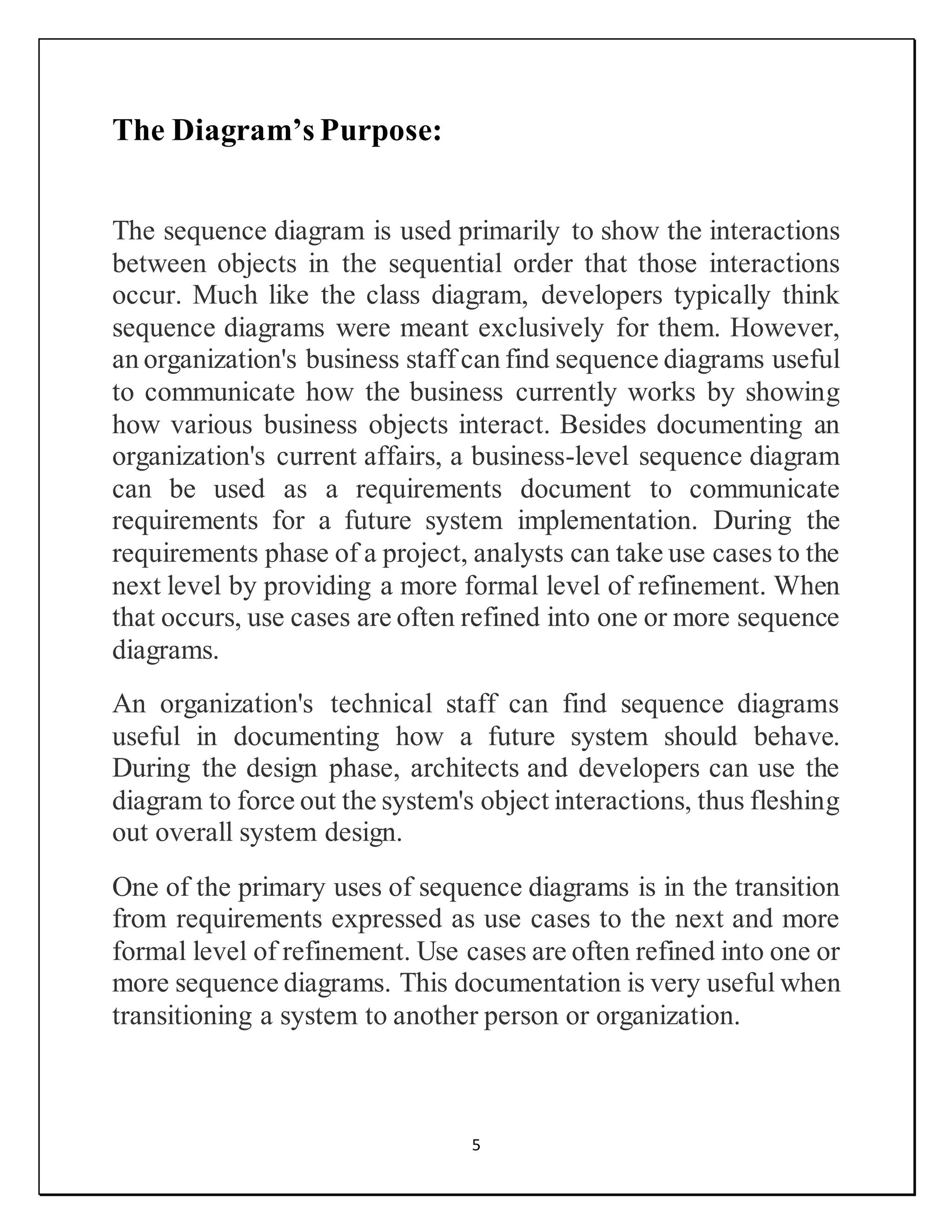
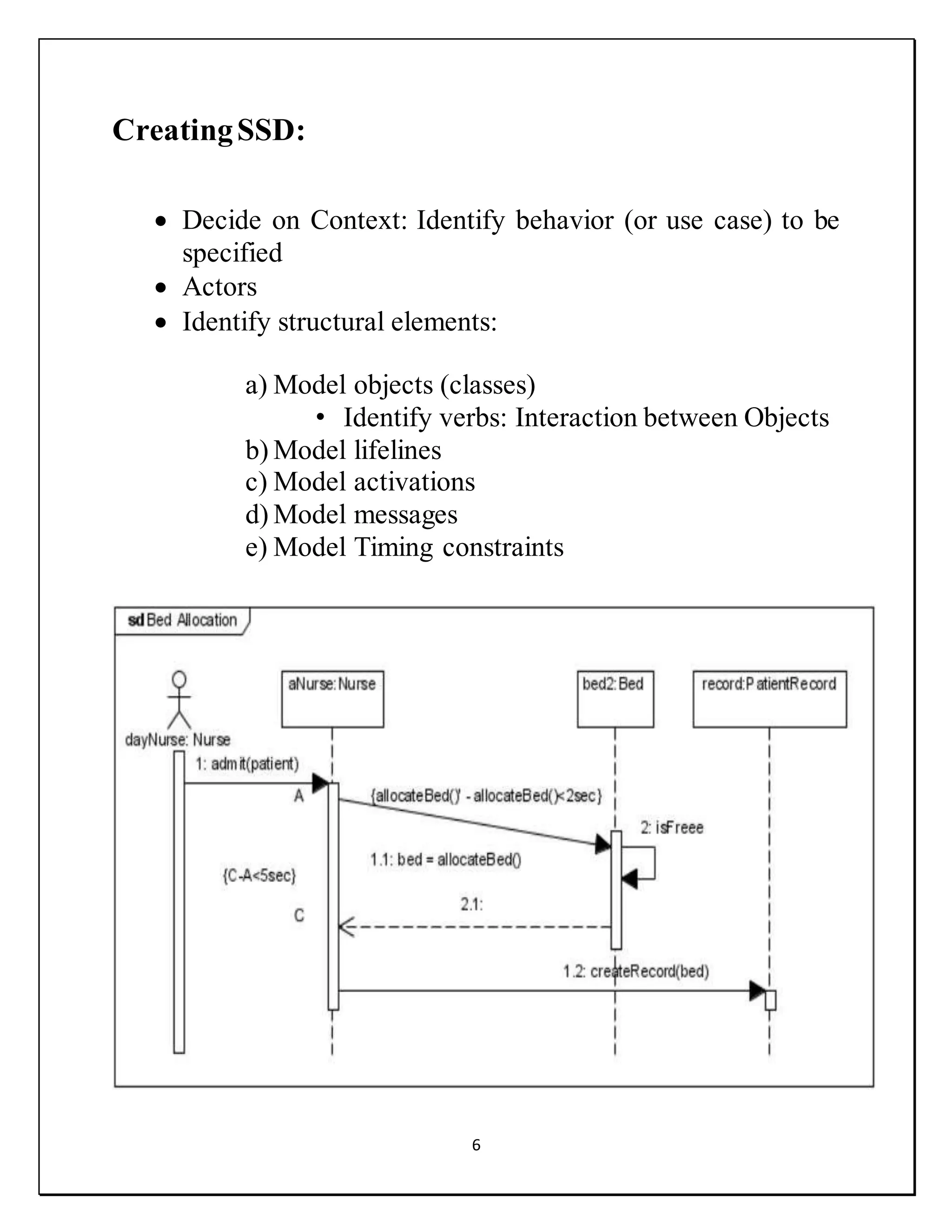
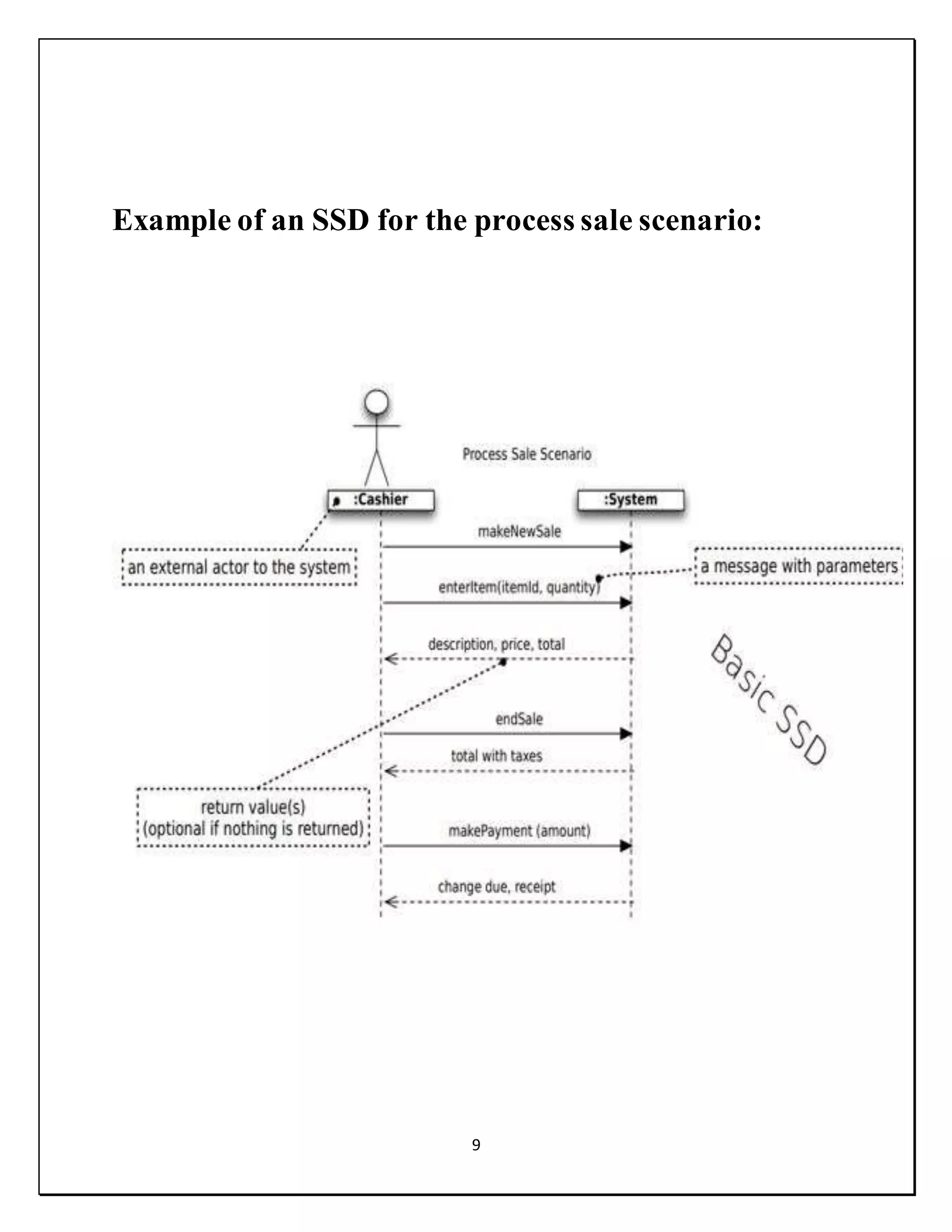
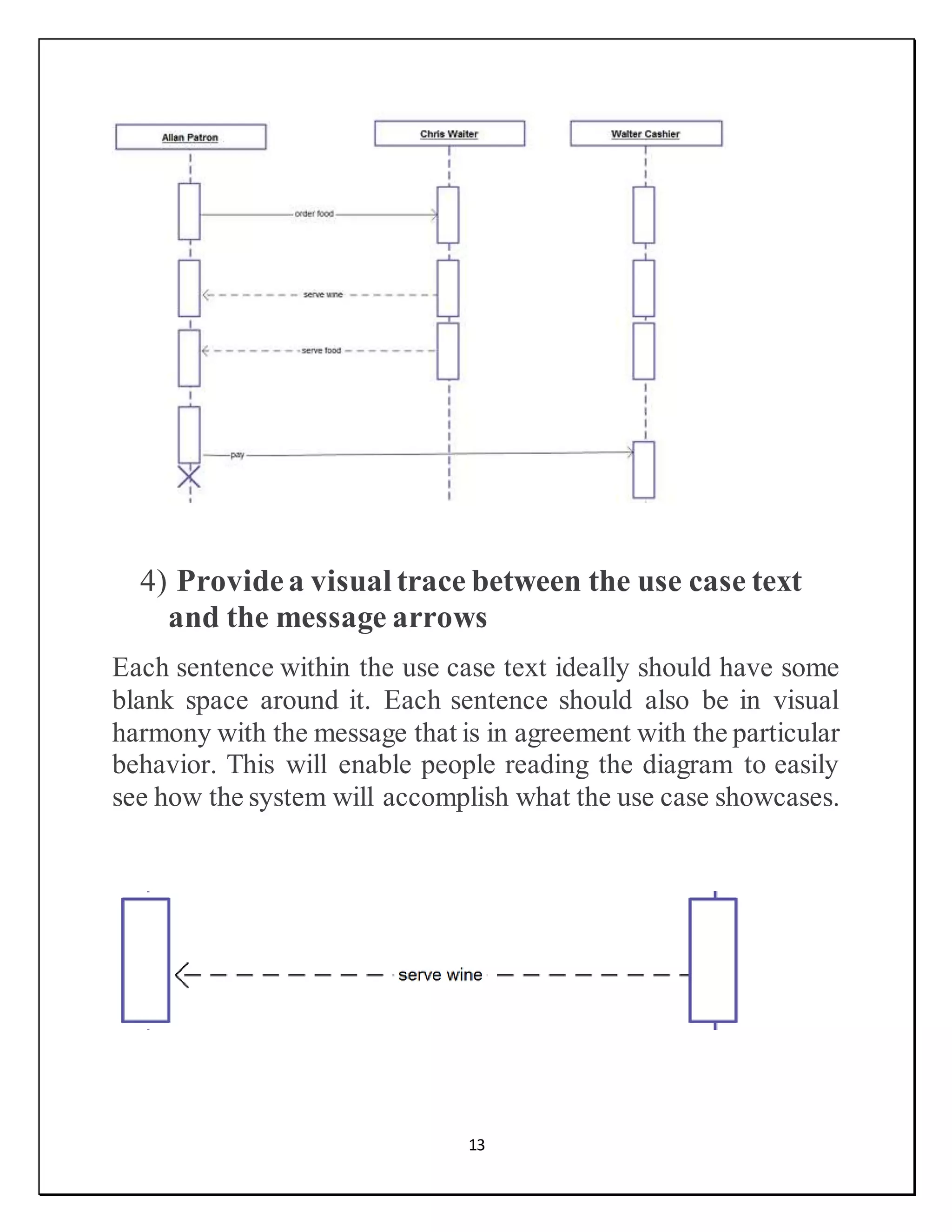
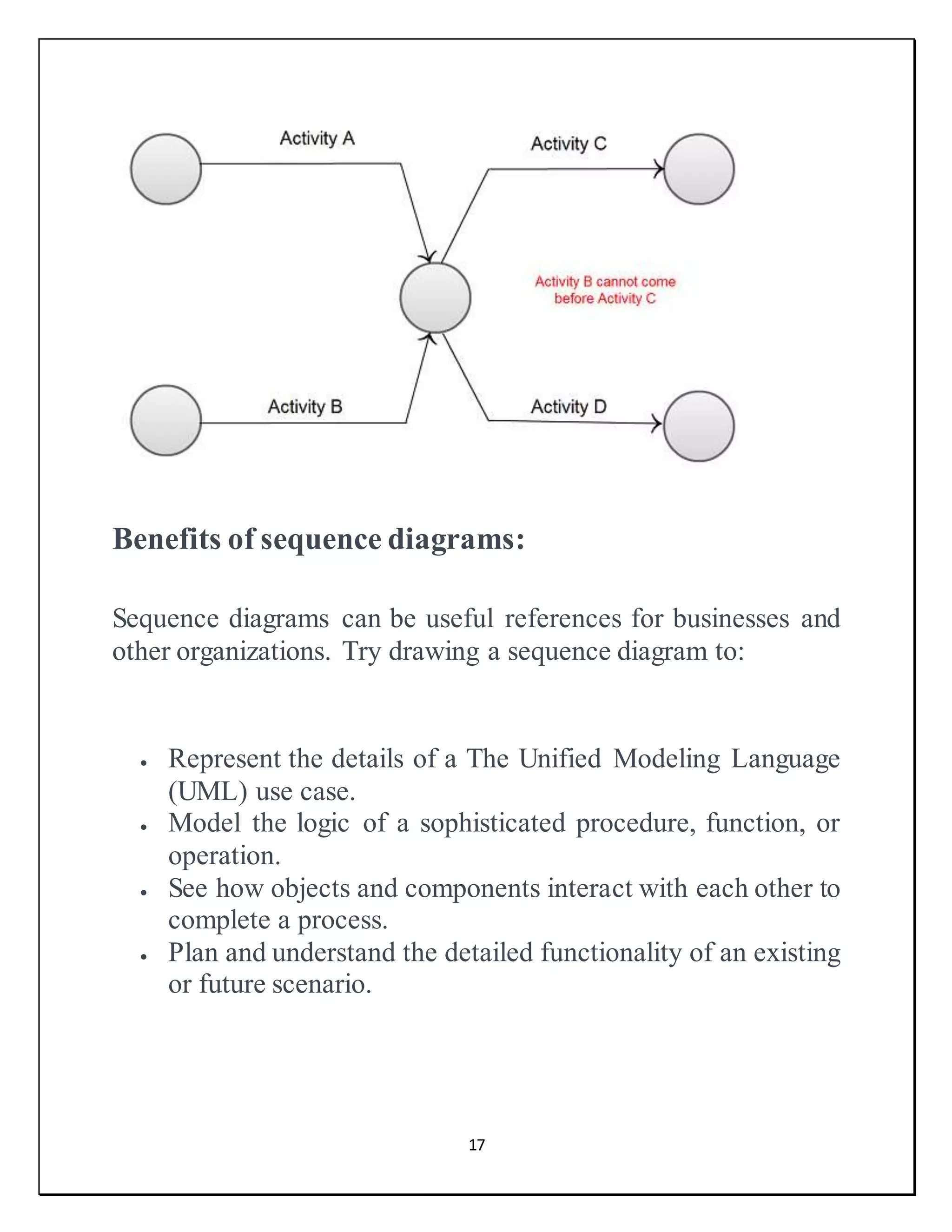
3. 3
Acknowledgements:
All praises are for Allah Almighty that has bestowed upon being
the crown of creation and has endowed him with knowledge and
wisdom. After Allah, the last Prophet Mohammad (PBUH) Who
brought for us revelation and unlimited knowledge and civilized
the barbarian human beings. Our very sincere acknowledgements
are of Ms. Faiza Ijaz, our instructor of Project Management. It is
because of her guidance we were able to learn so much from this
project and also gave us the opportunity to experience the best
report ever. We are proud to present on SSD behalf and we learn
our mistakes, from our efficiencies and from our respected
Ma’am.
4. 4
Introduction:
In software engineering, a system sequence diagram (SSD) is
a sequence diagram that shows, for a particular scenario of a use
case, the events that external actors generate, their order, and
possible inter-system events.
System sequence diagrams are visual summaries of the individual
use cases.
An SSD shows – for one particular scenario of a use case –
• The events that external actors generate,
• Their order, and
• Inter-system events
SSDs are derived from use cases; SSDs are often drawn for
the main success scenarios of each use case and frequent or
complex alternative scenarios
SSDs are used as input for object design.
5. 5
The Diagram’s Purpose:
The sequence diagram is used primarily to show the interactions
between objects in the sequential order that those interactions
occur. Much like the class diagram, developers typically think
sequence diagrams were meant exclusively for them. However,
an organization's business staff can find sequence diagrams useful
to communicate how the business currently works by showing
how various business objects interact. Besides documenting an
organization's current affairs, a business-level sequence diagram
can be used as a requirements document to communicate
requirements for a future system implementation. During the
requirements phase of a project, analysts can take use cases to the
next level by providing a more formal level of refinement. When
that occurs, use cases are often refined into one or more sequence
diagrams.
An organization's technical staff can find sequence diagrams
useful in documenting how a future system should behave.
During the design phase, architects and developers can use the
diagram to force out the system's object interactions, thus fleshing
out overall system design.
One of the primary uses of sequence diagrams is in the transition
from requirements expressed as use cases to the next and more
formal level of refinement. Use cases are often refined into one or
more sequence diagrams. This documentation is very useful when
transitioning a system to another person or organization.
6. 6
CreatingSSD:
Decide on Context: Identify behavior (or use case) to be
specified
Actors
Identify structural elements:
a) Model objects (classes)
• Identify verbs: Interaction between Objects
b) Model lifelines
c) Model activations
d) Model messages
e) Model Timing constraints
7. 7
Basicsymbols and components:
To understand what a sequence diagram is, you should be familiar
with its symbols and components. Sequence diagrams are made
up of the following icons and elements:
10. 10
Another example of ATM:
Example of an SSD for the
Process Sale Scenario:
Use Case: Process Sale Scenario - Main
Success Story
1. Cashier starts new sale
2. Cashier enters item identifier
3. System records sale line item and presents item description, price and running
total Steps 2 and 3 are repeated until all items are processed.
4. System presents total with taxes calculated
5. Cashier tells Customer the total and asks for payment
6. Customer pays and System handles payment
11. 11
Evaluation:
1) Get rid of unnecessarydetail
A typical mistake that software diagrammers usually make is
adding too much detail when working with sequence diagrams.
Say your code has quite a few branches in a particular method;
this does not mean that you should include each one within the
same diagram using block or scenario elements. The issue is that
adding too much detail ends up with too much clutter thereby
making the diagrams more difficult to read and comprehend. The
same could be said when it comes to sequence diagrams at the
system level. Main thing is to keep all your diagrams clutter-free,
as shown below.
2) Messages should(more often than not) run from
left to right
When it comes to sequence diagrams, the message flow should
start from the top left corner. Since it’s a practice in western
12. 12
culture to read from the left to the right, all classifiers such as
actors, classes, objects and use cases, should follow this route.
However, there are certain exceptions when it comes to this
logical flow, for example, when objects pairs invoke operations
on each other.
3) Avoid sequencediagrams if you are dealingwith
simple logic
One of the most common mistakes that most of us do is waste
precious time doing too many sequence diagrams for every single
use case, one for the basic course of action and one for each
alternate course. It is best to design a sequence diagram only
when you have complex logic that you have to deal with. If the
logic is simple and easy to assimilate, having a sequence diagram
would not really add any value.
13. 13
4) Providea visual trace between the use case text
and the message arrows
Each sentence within the use case text ideally should have some
blank space around it. Each sentence should also be in visual
harmony with the message that is in agreement with the particular
behavior. This will enable people reading the diagram to easily
see how the system will accomplish what the use case showcases.
14. 14
5) Keep your sequence diagrams abstractwithout
the need for plumbing
When it comes to robustness diagrams, there really is no need to
show plumbing, since these diagrams reflect a design view that is
preliminary. Having said that it is pertinent to highlight the real
design in detail since sequence diagrams are the last stop before
coding.
6) Include the use case text on the sequence diagram
Writing the text for the use case in the margin of the sequence
diagram provides a trace from the design back to your
requirements. In short, the diagram should match the narrative
flow of the associated use case.
15. 15
7) Followthe basics when it comes to allocating
behaviorby using message arrows
An object ideally should only possess a single personality. What
this means is thata class should ideally focus on a set of behaviors
that are strongly related. In other words, state objects need to be
cohesive and coupled loosely. Other aspects that you need to
concentrate on include things like reusability. What this means is
that when you have objects and classes that are general, you could
reuse them for other projects. Also remember that methods are
assigned to objects, make sure you make it a habit to ask whether
there is a decent fit between the method and object.
16. 16
8) Considerthe origins of the message arrows
carefully
This is a no brainer. You do have to see which object is in control
at whatever time so that it is easy to see the flow of control. While
the arrows are certainly important when it comes to robustness
diagrams, they are more important when it comes to sequence
diagrams. Remember that the messages that are present between
objects determines the operations on the associated classes.
17. 17
Benefits of sequence diagrams:
Sequence diagrams can be useful references for businesses and
other organizations. Try drawing a sequence diagram to:
Represent the details of a The Unified Modeling Language
(UML) use case.
Model the logic of a sophisticated procedure, function, or
operation.
See how objects and components interact with each other to
complete a process.
Plan and understand the detailed functionality of an existing
or future scenario.
18. 18
Conclusion:
The sequence diagram is a good diagram to use to document a
system's requirements and to flush out a system's design. The
reason the sequence diagram is so useful is because it shows the
interaction logic between the objects in the system in the time
order that the interactions take place.
Reference:
https://en.wikipedia.org/wiki/System_sequence_diagram
https://creately.com/blog/diagrams/10-common-mistakes-to-
avoid-in-sequence-diagrams/
https://www.lucidchart.com/pages/uml-sequence-diagram
https://www.ibm.com/developerworks/rational/library/3101.htm