
Recommended
More Related Content
What's hot
What's hot (20)
Similar to Dc4 t1
Similar to Dc4 t1 (20)
Recently uploaded
Recently uploaded (20)
Dc4 t1
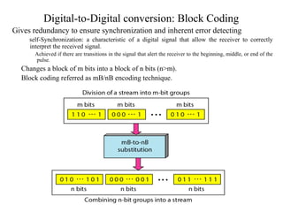
- 1. Digital-to-Digital conversion: Block Coding Gives redundancy to ensure synchronization and inherent error detecting self-Synchronization: a characteristic of a digital signal that allow the receiver to correctly interpret the received signal. Achieved if there are transitions in the signal that alert the receiver to the beginning, middle, or end of the pulse. Changes a block of m bits into a block of n bits (n>m). Block coding referred as mB/nB encoding technique.
- 2. –Involves three steps • Division: a sequence of bits is divided into groups of m bits. – Ex. 4B/5B: bit sequence divided into 4-bit groups. • Substitution: an m-bit group is substituted for an n-bit group. – Ex. 4B/5B: substitute 4-bit code for 5-bit group. • Combination: the n-bit groups are combined together to form a stream. – 4B/5B (four binary/five binary) • Used in combination with NRZ-I. • Prior to encoding with NRZ-I, change the bit stream to not contain a long sequence of 0s (i.e. to cancel NRZ-I synchronization problem). • The groups not used in the encoding are used for the control and error detection.
- 4. Substitution in 4B/5B block coding 4
- 5. –8B/10B (eight binary/ten binary) • Similar to 4B/5B except that a group of 8 bits of data is now substituted by a 10-bit code. Digital-to-Digital conversion: Scrambling Encoding of long distance communication Biphase codes are not suitable because of their wide bandwidth requirement. The combination of block coding and NRZ line coding is not suitable because of the DC component. DC component: occurs when a digital signal is constant for a while which creates very low frequencies. This presents a problem for the systems that cannot pass low freqeuncies. Bipolar AMI, however has a narrow bandwidth and does not create DC-component. However, a long sequence of 0s upsets the synchronization.
- 6. •Scrambling – Modify part of AMI to provide synchronization with a long sequence of 0s – Two techniques : B8ZS and HDB3 •B8ZS (Bipolar with 8-zero substitution) – Commonly used in north of America. – Eight consecutive zero-levels are replaced by the sequence 000VB0VB. • V denotes “violation”: a nonzero voltage that breaks the AMI rule of encoding. –i.e. same polarity as the polarity of the previous nonzero pulse. • B denotes “bipolar”: a nonzero voltage in accordance with the AMI rules. –i.e. an opposite polarity as the polarity of the previous nonzero pulse. – Such a scrambling does not change the bit rate. – There is a balance in the positive and negative voltage levels (2 positives and 2 negatives) • => DC balance is maintained.
- 7. • HDB3 (High-density bipolar 3-zero) – Commonly used outside the North America. – Four consecutive zero-level voltage are replaced with a sequence • 000V : if the number of nonzero pulses after the last substitution is odd. • B00V: if the number of nonzero pulses after the last substitution is even. • The first substitution is even (i.e. B00V).
- 8. 8 Analog-to-Digital conversion • A digital signal is superior to an analog signal. • The tendency today is to change an analog signal to digital data. • Two techniques can be used • PCM • Delta modulation. • PCM (Pulse Code Modulation) • Most commonly used technique to change an analog signal to digital data (digitization) • PCM encoder has three processes • Sampling • Quantization • Encoding
- 9. • Sampling • Sampling process also called PAM (Pulse Amplitude Modulation) • The analog signal is sampled every Ts. • Ts : sample interval. • 1/Ts : sampling rate or sampling frequency. Denoted by fs , where fs= 1/Ts –The sampling method • Ideal (not easily implemented): pulses from the analog signal are sampled. • Natural: A high-speed switch is turned on for only the small period of time when sampling occurs. – The result is a sequence of samples that retains the shape of the analog signal. • Sample and hold: creates flat-top samples by using a circuit. Most common method. – The result of the sampling process is still an analog signal
- 10. Three different sampling methods for PCM
- 11. – Sampling rate • Nyquist theorem: to reproduce the original analog signal the sampling rate should be at least equal to twice the highest frequency of the original signal. – Example • Telephone companies digitize voice assuming a maximum frequency of 4000Hz. – The sampling rate is therefore 8000 samples per second. •What sampling rate is needed for a signal with a bandwidth of 10000Hz [1000,11000]Hz? – The sampling rate must be twice the highest frequency of the signal – Sampling rate = 2*11000 = 22000 samples/second. • A complex low-pass signal has a bandwidth of 200KHz. What is the minimum sampling rate for this signal? – The bandwidth of a low-pass signal is between 0 and f (f is the maximum frequency). – So f=200KHz and the sampling is done at : 2*200KHz=400000 samples/s. •Quantization – Steps of quantization 1. Assume the original analog signal has instantaneous amplitudes between Vmin and Vmax. 2. Divide the range into L zones each of high ∆ • Formula : ∆= Vmax–Vmin / L 1. Assign quantized values of 0 to L-1 to the midpoint of each zone. 2. Approximate the value of the sample amplitude to the quantized values.
- 12. – Quantization levels • The choice of L, the number of levels, depend on the range of the amplitudes of the analog signal and the accuracy to recover the signal. – If the amplitude fluctuates between two levels => L=2. – With audio digitizing => L=256. –Quantization errors • The input values to the quantizer are the real values. • The output values are the approximate values and are chosen in the middle of the zone. • The difference between the real values and the approximate values is the quantization error. – Example • Assume a sample signal with the sample amplitudes in [-20,20]V. Nine samples are shown using ideal sampling. • Quantization levels with L=8 => ∆=5
- 13. •Quantization Example (cont’d) –The value at the top of each sample in the graph is the actual amplitude. – 1st row : the normalized value for each sample (actual amplitude/∆). – 2nd row : the normalized quantized value chosen from the middle of each zone. – 3rd row : the normalized error. – 4th row: quantization code for each sample based on the quantization levels (left of the graph). – 5th row: the encoded words which are the final products of the conversion. •Encoding – After each sample has been quantized and the number of bit per samples is decided, each sample can be changed to an nb-bit code word. – The number of bits for each sample is determined from the number of levels L: nb = log2L
- 14. –Previous example • nb = log2L = 3bits. A quantization code of 2 is encode as 010. –Bit rate = sampling rate * number of bits per sample => Bit rate = fs* nb – Example • What is the bit rate to digitize the human voice assuming 8 bits per sample. –Frequencies of the human voice [0,4000]Hz. Sampling rate = 4000*2 = 8000 samples/s Bit rate = 8000*8 = 64000 bps = 64 Kbps. •Signal recovery – Requires a PCM decoder. – The decoder converts the code words into a pulse that holds the amplitude until the next pulse. – The resultant staircase signal is passed through a low-pass filter to smooth it into an analog signal. • The filter has the same cutoff frequency as the original signal at the sender. – If the signal has been sampled >= the Nyquist sampling rate and if there is enough quantization levels => the original signal will be recreated. – The minimum and maximum values of the original signal can be achieved by using amplification.
- 15. 15 Transmission modes • Transmission of binary data across a link can be one of the following modes – Parallel mode • Data is grouped into groups of n bits. • n bits are sent with each clock tick. • Use n wires to send these n bits at a time. – The n wires are typically bundled into a cable with a connector at each end. • Advantage: speed – Can increase the speed by a factor of n over serial transmission • Drawback : cost – Requires n communication wires. – => usually limited to short distance. • Parallel transmission
- 16. –Serial mode • One bit is sent in each clock tick. • Needs only one communication channel between the two communicating devices • Advantages: reduced cost – Only one communication channel is used. • Communication within devices is parallel • => need conversion devices at the interfaces between the sender and the line (parallel-to-serial) and between the line and the receiver (serial-to-parallel). • Serial communication occurs in three ways – Asynchronous – Synchronous – Isochronous. • Serial transmission
- 17. •Asynchronous transmission – The timing of the signal is unimportant. – Agreed patterns allow the receiver to retrieve the information without regard to the rhythm in which it is sent. • Patterns based on grouping bit stream into bytes (usually 8 bits) • The sender handles each byte independently. – It sends the byte into the link whenever ready without regard to a timer –Start bit – stop bit • Start bit (usually 0) – An extra bit added to the beginning of each byte to alert the receiver of the arrival of a new byte. • Stop bits (usually 1s) – One or more extra bits added at the end of the byte to let the receiver know the end of the byte. – The transmission of each byte may then be followed by a gap of varying duration. • The gap is represented by an idle channel or by a stream of additional stop bits – Meaning of asynchronous • At the byte level, the sender and the receiver need not to be synchronized. • Within each byte, although, the receiver must be synchronized with the incoming stream. – When the receiver detects the start-bit, it sets a timer and begins counting bits as they come in – After n bits, the receiver looks for a stop bit.
- 18. –Advantages • Cheaper and effective. • Used for slow-speed communication (keyboard-computer) – Drawbacks • Slow because of the insertion of start-bit, stop-bit, and gaps • Synchronous transmission – The bit stream combined into frames. • A frame contains multiple bytes. • No gaps between a byte and the next byte belonging to the same frame. • Receiver’s responsibility to group the bits into bytes (or in characters) to reconstruct the information.
- 19. –There may be uneven gaps between frames filled with idle (special sequence of 0s and 1s). – Timing is important because to allow the receiver to keep an accurate count of the bits as they come. • Byte synchronization is accomplished in the data link layer. – Advantages • Speed because of no extra bits or gaps. • Helpful for high-speed transmission (computer-computer) •Isochronous transmission – Guarantees that the data arrive at a fixed rate. • Uneven delays between frames (i.e. synchronous transmission) are not acceptable. – TV images are broadcast at the rate of 30 images/s to be viewed. – If each image is sent by using one or more frame, they should be no delays between frames. • Synchronization between characters is not enough, entire stream of bits must be synchronized.
- 20. Analog transmission •Recall - Digital transmission needs a low-pass channel. - Band pass channel=>Analog transmission •Analog conversions –Digital-to-analog conversion •Converting digital data to a band pass signal. –Analog-to-analog conversion •Converting a low-pass analog signal to a band pass analog signal. •Digital-to-analog conversion -Process of changing one of the characteristics of an analog signal based on the information in digital data.
- 21. –Change one of the characteristic of a sine wave (amplitude, frequency, and phase) to represent digital data. •Change of one of these characteristics gives a different version of the wave. –The techniques to modulate digital data into an analog signal •ASK(Amplitude Shift Keying). •FSK(Frequency Shift Keying). •PSK(Phase Shift Keying). •QAM (Quadrature Shift Keying) :combines the amplitude and phase. Most efficient technique used today
- 22. Analog transmission: digital-to-analog •Aspect of digital-to-analog transmission –Carrier signal •In analog transmission, the sender produces a high-frequency signal that acts as a base for the information signal called carrier signal (or carrier frequency). •The receiver is tuned to the frequency of the carrier signal expected from the sender. •Modulation (shift keying) is the change on the carrier signal by modifying one or more characteristics (amplitude, frequency, or phase) according to the digital information. •ASK(Amplitude Shift Keying) –The amplitude of the carrier signal is varied to create signal elements. •Both frequency and phase remain constant while the amplitude changes.
- 23. 23 •Binary ASK (or on-off keying (OOK)) • Use only two levels (kinds) of signal element each with a different amplitude. – The peak amplitude of one signal level is 0. – The other is the same as the amplitude of the carrier frequency. ∈
- 24. 24 Analog transmission: digital-to-analog •ASK (Amplitude Shift Keying) – Multilevel ASK • More than two amplitude levels are used. – 4, 8, 16 or more different amplitudes for the signal are used. – Modulate the data using 2, 3, 4, or more bits at a time. – Not implemented with pure ASK but implemented with QAM. •FSK (Frequency Shift Keying) – The frequency of the carrier is varied to represent data. • The frequency of the modulated signal is constant during the duration of one signal element but changes for the next signal element if the data element changes. •Both amplitude and phase remain constant. – Binary FSK (BFSK) • Two carriers frequencies are considered. – One with f1(for bit 0) and the other with f2(for bit 1).
- 25. -Multilevel FSK Use more than one frequency. Ex.: use 4 frequencies (f1, f2, f3, and f4) to send 2 bits at a time. Ex.: use 8 frequencies to send 3 bits at a time.
- 26. 26 Analog transmission: digital-to-analog• PSK (Phase Shift Keying) –The phase of the carrier is varied to represent two or more signal elements. • Both amplitude and frequency remain constant. –Binary PSK (BPSK) • Only two signal elements are used –One with a phase of 0 degree and the other with a phase of 180 degrees. •Today PSK is more common than ASK or FSK. •Advantage –As simple as ASK but less susceptible to noise. • Noise can change the amplitude easier than it can change the phase –PSK is superior to FSK because we do not need two carrier signals. – Quadrature PSK (QPSK) • 2 bits are encoded in each signal element.
- 27. 27 Analog transmission: digital-to-analog • PSK (cont’d) – QPSK (cont’d) • Constellation diagram • Help to define the amplitude and the phase of a signal element especially when using two carriers. • Useful when dealing with multilevel ASK, PSK, and QAM. • A signal element type is represented by as a dot. • The bit or combination of bits it can carry is often written next it • Example • Show the constellation diagram of an ASK (OOK), BPSK, and QPSK signals. - ASK: Binary 0 has an amplitude of 0 and binary 1 has an amplitude of 1V for example. - BPSK: 2 different signal elements are used, one with amplitude 1V and in-phase and the other with an amplitude 1V and 180 out-of phase. - QPSK: for example, the point representing 11 is made of two combined signal elements, both with an amplitude of 1V. One element is represented by an in-phase carrier and the other element by a quadrature carrier. The amplitude of the final element sent for this 2-bits data element is 21/2 , and the phase is 45 degree.
- 28. 28 Analog transmission: digital-to-analog • QPSK (cont’d) – Example (cont’d) • QAM (Quadrature Amplitude Modulation) –PSK is limited by the ability of the equipment to distinguish differences in phases. –So far, we have been altering only one of the three characteristics of a sine wave. What if we alter two? –Why not combine ASK and PSK? => QAM –QAM: use two carriers • One in-phase • The other quadrature • With different amplitude levels for each carrier. –Possible variations of QAM are numerous.
- 29. 29 Analog transmission: analog-to-analog • Representation of analog information by an analog signal. – Such modulation is needed if the medium is bandpass or only a bandpass channel is available. • EX.: Radio transmissions – Governments assign a narrow bandwidth to each radio station. – The analog signal produced by each station is a low-pass signal, all in the same range. – The low pass signal of each station need to be shifted to a different range. – Three possible analog-to-analog conversions • AM (Amplitude Modulation) • FM (Frequency Modulation) • PM (Phase Modulation). • AM –The carrier signal is modulated so that its amplitude varies with the changing amplitudes of the modulating signal. • Phase and frequency of the carrier remain the same.
- 30. 30 Analog transmission: analog-to-analog• AM (cont’d) – Standard bandwidth allocation for AM radio • The bandwidth of an audio signal (speech and music) is usually 5 KHz. • An AM station bandwidth should be 10KHz. • Federal Communication Commission (FCC) – AM stations are allowed frequencies in [530, 1700]KHz – Each AM station is assigned 10KHz. – To avoid interference: each station carrier frequency must be separated from those on either sides by at least 10KHz. • FM –The frequency of the carrier signal is modulated to follow the voltage level (amplitude) of the modulated signal. • The peak amplitude and the phase of the carrier signal remain constant.
- 31. 31 Analog transmission: analog-to-analog• FM (cont’d) –Standard Bandwidth Allocation for FM Radio • Bandwidth of an audio signal broadcast in stereo is 15KHz. • FCC allows 200KHZ for each station. • FM stations allowed carrier frequencies in [88, 108]MHz. • Stations separated by 200KHz. • To avoid more interfering, alternate bandwidth allocation may be used. • PM – The phase of the carrier signal is modulated to follow the changing amplitude of the modulated signal. • The peak amplitude and the frequency of the carrier signal remain constant. • Proved mathematically: PM is the same as FM.