Multilevel half rate phase detector for clock and data recovery circuits

In this brief, a half-rate (HR) bang-bang (BB) phase detector (PD) with multiple decision levels is proposed for clock and data recovery (CDR) circuits. The combination allows the oscillator to run at half the input data rate while providing information about the sign and magnitude of the phase shift between the PD inputs. This allows a finer control of the frequency of the oscillator in the phase-locked loop (PLL) of the CDR circuit, which results in up to 30% less output clock jitter than with a conventional two-levels HR BB PD. Thanks to this, the bit error rate can be decreased by up to 5× in a 5-Gb/s CDR circuit. The proposed topology was implemented in a 28-nm FDSOI CMOS technology providing average power consumption below 76 µW with a supply voltage of 1 V. Although multilevel (ML) BB PDs have already been proposed in some PLL-based CDR with very interesting results, a specific design of the PD has to be implemented for an HR system. This brief provides the first ML-HR-BBPD.

Recommended
Recommended
More Related Content
Similar to Multilevel half rate phase detector for clock and data recovery circuits
Similar to Multilevel half rate phase detector for clock and data recovery circuits (20)
More from Nxfee Innovation
More from Nxfee Innovation (6)
Recently uploaded
Recently uploaded (20)
Multilevel half rate phase detector for clock and data recovery circuits
- 1. NXFEE INNOVATION (SEMICONDUCTOR IP &PRODUCT DEVELOPMENT) (ISO : 9001:2015Certified Company), # 45, Vivekanandar Street, Dhevan kandappa Mudaliar nagar, Nainarmandapam, Pondicherry– 605004, India. Buy Project on Online :www.nxfee.com | contact : +91 9789443203 | email : nxfee.innovation@gmail.com _________________________________________________________________ Multilevel Half-Rate Phase Detector for Clock and Data Recovery Circuits Abstract: In this brief, a half-rate (HR) bang-bang (BB) phase detector (PD) with multiple decision levels is proposed for clock and data recovery (CDR) circuits. The combination allows the oscillator to run at half the input data rate while providing information about the sign and magnitude of the phase shift between the PD inputs. This allows a finer control of the frequency of the oscillator in the phase-locked loop (PLL) of the CDR circuit, which results in up to 30% less output clock jitter than with a conventional two-levels HR BB PD. Thanks to this, the bit error rate can be decreased by up to 5× in a 5-Gb/s CDR circuit. The proposed topology was implemented in a 28-nm FDSOI CMOS technology providing average power consumption below 76 µW with a supply voltage of 1 V. Although multilevel (ML) BB PDs have already been proposed in some PLL-based CDR with very interesting results, a specific design of the PD has to be implemented for an HR system. This brief provides the first ML-HR-BBPD. Software Implementation: Modelsim Xilinx 14.2 Existing System: Clock and data recovery (CDR) is a key function in many serial communication systems, from optical to electrical communications, but especially for high-speed signaling. The performance of the clock recovery is crucial for the reliability of the communication system, especially important to perform synchronous operations such as the retiming and
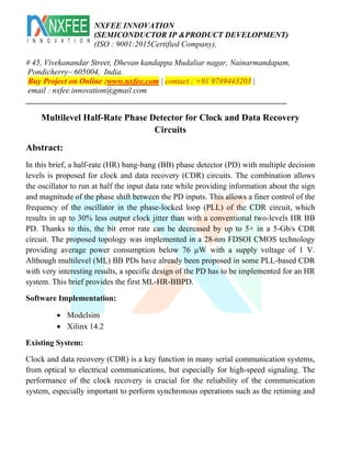
- 2. NXFEE INNOVATION (SEMICONDUCTOR IP &PRODUCT DEVELOPMENT) (ISO : 9001:2015Certified Company), # 45, Vivekanandar Street, Dhevan kandappa Mudaliar nagar, Nainarmandapam, Pondicherry– 605004, India. Buy Project on Online :www.nxfee.com | contact : +91 9789443203 | email : nxfee.innovation@gmail.com _________________________________________________________________ demodulation of the input data. Jitter in the clock, defined as the uncertainty in the edge placement in the clock waveform, results in distortion of the data signals waveforms. This jitter translates in oscillator phase deviation from ideal, which results in phase noise. Although other systems such as delay-locked loops or phase interpolator-based CDR are used in some cases, phase locked loops (PLLs) are the most widespread systems to implement a reference-less CDR. Fig. 1 shows the general block diagram of a PLL based CDR. It is composed of a voltage-controlled oscillator (VCO), which generates the required clock, a phase detector (PD), which compares the phase of the generated clock to that of the randomized input data, and a charge pump (CP), which charges or discharges a loop filter (LF) to generate the required control signal for the VCO. The PD is one of the critical blocks of the CDR as it determines the phase error between the input data and the clock, which conditions the control voltage for the VCO, and therefore the correct agreement between the clock and data edges. Although a linear PD is sometimes used, a binary or bang bang (BB) PD is usually preferred in high-speed CDRs due to its simplicity, good phase adjustment, high-speed operation, and low power. The BBPD provides a binary output, which gives information about the sign of the phase shift between its inputs, i.e., if the clock is lagging or leading the input data.
- 3. NXFEE INNOVATION (SEMICONDUCTOR IP &PRODUCT DEVELOPMENT) (ISO : 9001:2015Certified Company), # 45, Vivekanandar Street, Dhevan kandappa Mudaliar nagar, Nainarmandapam, Pondicherry– 605004, India. Buy Project on Online :www.nxfee.com | contact : +91 9789443203 | email : nxfee.innovation@gmail.com _________________________________________________________________ Fig. 1. Block diagram of a PLL-based CDR showing the parameters used in our Verilog-AMS model. The Alexander PD or variations of it, such as the inverse Alexander PD where the outputs (Early and Late) are inverted (Late and Early), are the most commonly used PD in high speed designs. Other topologies have been presented but their complexity is increased. All these Alexander-based PDs work at a full-rate clock frequency; which means that the frequency of oscillation of the VCO is the same as the data rate of the input data. At high speed, a half-rate PD (HR-PD) is very useful to reduce the requirements of the VCO and increase the throughput of the system. CDRs implemented with an HR-PD sense the input data at full rate but use a VCO running at half the input rate. This technique also relaxes the speed requirement of the PD. In this brief, we propose a new multilevel HR BB PD (ML-HR-BBPD). Thanks to the ML operation that provides information about the sign and the magnitude of the phase difference between the PD inputs, the bit error rate (BER) performance of the output data as well as the jitter of the clock generated with a PLL-based CDR is improved compared to the conventional two-levels HR-PD. Although ML-BBPD have been already proposed in some PLL-based CDR with very interesting results , to our best knowledge, they have never been proposed for an HR system. The main objective of this brief is, therefore, to provide an ML alternative to the conventional HR-PD and perform a comparison of the two topologies. For that the two PDs have been included in a PLL-based CDR system that is used as a test bench for comparison. Disadvantages: High power is needed Low speed operation Complex in operation
- 4. NXFEE INNOVATION (SEMICONDUCTOR IP &PRODUCT DEVELOPMENT) (ISO : 9001:2015Certified Company), # 45, Vivekanandar Street, Dhevan kandappa Mudaliar nagar, Nainarmandapam, Pondicherry– 605004, India. Buy Project on Online :www.nxfee.com | contact : +91 9789443203 | email : nxfee.innovation@gmail.com _________________________________________________________________ Proposed System: Proposed multilevel half-rate phase detector As a tradeoff between pure linear and pure BB HR-PD, we propose an ML-HR-BBPD whose schematic is given in Fig. 2. The digital nature of the BB HR-PD is not altered but we have further levels of quantization to measure the phase difference. This results in a reduction of jitter because of the finer corrections to the VCO frequency when the system has locked in phase. As shown in Fig. 2, the proposed phase detection scheme uses more samples of the data: apart from the edge samples E0 and E1 (generated by the rising edges of 0 and 180 and data sample D0 (by 90) like in the standard topology, additional mid-samples M0 and M1 (generated by 45 and 135) are provided.
- 5. NXFEE INNOVATION (SEMICONDUCTOR IP &PRODUCT DEVELOPMENT) (ISO : 9001:2015Certified Company), # 45, Vivekanandar Street, Dhevan kandappa Mudaliar nagar, Nainarmandapam, Pondicherry– 605004, India. Buy Project on Online :www.nxfee.com | contact : +91 9789443203 | email : nxfee.innovation@gmail.com _________________________________________________________________ Fig. 2. Schematic of the proposed ML-HR-BBPD Fig. 3. Operation principle of the proposed ML-HR-BBPD. Relation between the clock phases and the input data for different operation conditions (left). Digital output as a function of the phase shift between the clock and the data (right). frequency must be decreased. Vice versa, if the samples taken by 90 and 135 are equal but different from 180, the clock is late (Late1) and the clock frequency must be increased. But now, if the samples taken by 0, and 45 are equal but different from 90, the clock is early and far from the lock condition (Early2) and the clock frequency must be decreased more. Vice versa, if the samples taken by 0, 45, and 90 are equal but different from 135 and 180, the clock is late (Late2) and far from the lock condition and the clock frequency must be increased more. This is summarized as
- 6. NXFEE INNOVATION (SEMICONDUCTOR IP &PRODUCT DEVELOPMENT) (ISO : 9001:2015Certified Company), # 45, Vivekanandar Street, Dhevan kandappa Mudaliar nagar, Nainarmandapam, Pondicherry– 605004, India. Buy Project on Online :www.nxfee.com | contact : +91 9789443203 | email : nxfee.innovation@gmail.com _________________________________________________________________ The operation of the proposed phase detection scheme comprises four levels of quantization (Fig. 3): positive high phase shift, positive low phase shift, negative low phase shift, and negative high phase shift. In this way, it provides a finer control of the frequency of the VCO in the CDR circuit, which results in a reduced jitter compared Fig. 4. Schematic design of the DFF
- 7. NXFEE INNOVATION (SEMICONDUCTOR IP &PRODUCT DEVELOPMENT) (ISO : 9001:2015Certified Company), # 45, Vivekanandar Street, Dhevan kandappa Mudaliar nagar, Nainarmandapam, Pondicherry– 605004, India. Buy Project on Online :www.nxfee.com | contact : +91 9789443203 | email : nxfee.innovation@gmail.com _________________________________________________________________ Fig. 5. (a) Top-level and (b) schematic design of the XOR gates. to purely binary phase detection schemes Schematic design To implement the proposed ML-HR-PD three different blocks are needed: DFF, XOR gates, and AND gates. The schematic design of the DFF is shown in Fig. 4. It has been implemented with a basic true-single-phase-clock edge-triggered CMOS DFF, which provides the flip-flop operation at high-speed with low power consumption (typically 64.7 μW at 10-GHz clock). Full-static CMOS logic is used to implement both XOR and AND gates, in preference to source-coupled logic (SCL) or dynamic logic. Although SCL logic can provide an advantage in speed, full-static CMOS gates are fast enough to
- 8. NXFEE INNOVATION (SEMICONDUCTOR IP &PRODUCT DEVELOPMENT) (ISO : 9001:2015Certified Company), # 45, Vivekanandar Street, Dhevan kandappa Mudaliar nagar, Nainarmandapam, Pondicherry– 605004, India. Buy Project on Online :www.nxfee.com | contact : +91 9789443203 | email : nxfee.innovation@gmail.com _________________________________________________________________ achieve few Gb/s in sub-90-nm CMOS technologies, and present a rail-to-rail output swing and no static power consumption. Although dynamic CMOS logic can provide an increased speed and in some cases reduced implementation area, in modern digital technology (after the 0.35-μm era), full static CMOS is the dominating logic, especially considering power consumption, noise, and clock skew problems. The AND gate is formed by a standard NAND gate plus an inverter so that only when both A and B are equal to a logic 1, both P1 and P2 are OFF and both N0 and N1 are ON, generating a Z equal to logic 0 and, therefore, an output equal to logic 1. To implement the XOR gates a topology based on transmission gates have been used (Fig. 5). As shown in Fig. 5(a), the top circuit implements an XOR function with two CMOS transmission gates and four inverters. Therefore Fig. 5(b) shows the schematic implementation. Transistors P4, P5, N4, and N5 forms the transmission gates and P1–P3, N1–N3 constitute the inverters of the XOR operation. Pi and Ni form the last inverter Advantages: Good phase adjustment Low power is provided High speed operation Simple in operation References: [1] B. Razavi, “Challenges in the design high-speed clock and data recovery circuits,” IEEE Commun. Mag., vol. 40, no. 8, pp. 94–101, Aug. 2002.
- 9. NXFEE INNOVATION (SEMICONDUCTOR IP &PRODUCT DEVELOPMENT) (ISO : 9001:2015Certified Company), # 45, Vivekanandar Street, Dhevan kandappa Mudaliar nagar, Nainarmandapam, Pondicherry– 605004, India. Buy Project on Online :www.nxfee.com | contact : +91 9789443203 | email : nxfee.innovation@gmail.com _________________________________________________________________ [2] B. Casper, “Clocking wireline systems: An overview of wireline design techniques,” IEEE Solid State Circuits Mag., vol. 7, no. 4, pp. 32–41, Sep. 2015. [3] C. H. Son and S. Byun, “On frequency detection capability of full-rate linear and binary phase detectors,” IEEE Trans. Circuits Syst. II, Exp. Briefs, vol. 64, no. 7, pp. 757–761, Jul. 2017. [4] J. Lee, K. S. Kundert, and B. Razavi, “Analysis and modeling of bangbang clock and data recovery circuits,” IEEE J. Solid-State Circuits, vol. 39, no. 9, pp. 1571–1580, Sep. 2004. [5] J. D. H. Alexander, “Clock recovery from random binary signals,” Electron. Lett., vol. 11, no. 22, pp. 541–542, 1975. [6] M. Verbeke, P. Rombouts, X. Yin, and G. Torfs, “Inverse Alexander phase detector,” Electron. Lett., vol. 52, no. 23, pp. 1908–1910, 2016. [7] D. Rennie and M. Sachdev, “A novel tri-state binary phase detector,” in Proc. IEEE Int. Symp. Circuits Syst., New Orleans, LA, USA, May 2007, pp. 185–188. [8] M. Ramezani, C. Andre, and T. Salama, “Analysis of a half-rate bangbang phase-locked-loop,” IEEE Trans. Circuits Syst. II, Analog Digit. Signal Process., vol. 49, no. 7, pp. 505–509, Jul. 2002. [9] G. Shu et al., “A reference-less clock and data recovery circuit using phase-rotating phase-locked loop,” IEEE J. Solid-State Circuits, vol. 49, no. 4, pp. 1036–1047, Apr. 2014. [10] C. Sanchez-Azqueta, C. Gimeno, C. Aldea, and S. Celma, “New multilevel bang-bang phase detector,” IEEE Trans. Instrum. Meas., vol. 62, no. 12, pp. 3384–3386, Dec. 2013. [11] G. de Streel et al., “SleepTalker: A ULV 802.15.4a IR-UWB transmitter SoC in 28-nm FDSOI achieving 14 pJ/b at 27 Mb/s with channel selection based on adaptive FBB and digitally programmable pulse shaping,” IEEE J. Solid-State Circuits, vol. 52, no. 4, pp. 1163–1177, Apr. 2017. [12] M. K. Raja, D. L. Yan, and A. B. Ajjikuttira, “A 1.4-psec jitter 2.5-Gb/s CDR with wide acquisition range in 0.18-μm CMOS,” in Proc. ESSCIRC, Sep. 2007, pp. 524–527. [13] D. H. Baek, B. Kim, H.-J. Park, and J.-Y. Sim, “A 5.67 mW 9 Gb/s DLL-based reference-less CDR with pattern-dependent clock-embedded signaling for intra-panel interface,” in IEEE Int. Solid-State Circuits Conf. (ISSCC) Dig. Tech. Papers, Feb. 2014, pp. 48–49