
Recommended
More Related Content
What's hot
What's hot (20)
Similar to Flame photometer, History, with spectrum, Principal, component of flame photometer, Operational Procedure, Defect and their Removal
Similar to Flame photometer, History, with spectrum, Principal, component of flame photometer, Operational Procedure, Defect and their Removal (20)
More from Muhammad Naveed Laskani
More from Muhammad Naveed Laskani (20)
Recently uploaded
Recently uploaded (20)
Flame photometer, History, with spectrum, Principal, component of flame photometer, Operational Procedure, Defect and their Removal
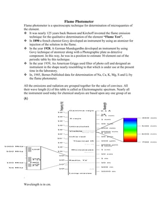
- 1. Flame Photometer Flame photometer is a spectroscopic technique for determination of microquanties of the element. It was nearly 125 years back Bunson and Kirchoff invented the flame emission technique for the qualitative determination of the element “Flame Test”. In 1890 a french chemist Govy developed an instrument by using an atomizer for injection of the solution in the flame. In the year 1928, A German Mundegardhn developed an instrument by using Govy technique of atomizer along with a Photographic plate as detective component. In this way, he was in a position to estimate 30 element out of the periodic table by this technique. In the year 1939, An American Griggs used filter of photo cell and designed an instrument in the shape nearly resembling to that which is under use at the present time in the laboratory. In, 1945, Bernes Published data for determination of Na, Ca, K, Mg, S and Li by the flame photometer. All the emissions and radiation are grouped together for the sake of convince. All their wave length (λ) of this table is called as Electromagnetic spectrum. Nearly all the instrument used today for chemical analysis are based upon any one group of an (λ) . Wavelength is in cm.
- 2. Hertz:- A frequency cycle in which No. of time a wavelength itself in one second. Electromagnetic spectrum:- Infra Red:- Waves are emitted by hot bodies and can be detected by special type of Photographic plate where as Hertzian cannot detected by Photographic plate. i. I.R used for detection of organic compound ii. Detection of rheumatoid arthritis(RA) using infrared imaging. iii. Keeping the meat Hot. iv. For the spying Purpose Visible Spectrum:- Waves can be detected by Photographic plate or Cameras. Those can be produce by artificial or natural illumenous bodies. LASER:- Light Amplification Synchronized Emitting Radiation They are produced by high light intensity upon Ruby stone. i. cutting glass steel Ultra-Violet:- Are produced by ionization of gazer. i. Used in calorimeter or spectro photometer for chemical analysis. ii. Deep calorization of the cloth. iii. For sterilization purpose iv. Destruction purpose X-Rays:- Those are produced when the fast moving electron in a vacuum are suddenly stopped with the result that they can pass through opaque bodies can be detected by Photographic plates and invisible to human eye. Alpha(α), Beta(β), Gemma(γ) Rays:- Are produced by disintegration of atomic nucleus. They produce heat and their frequency very high. i. Used disease control in Seed plant To observe composition of crystal Principal of Flame Photometer:- Working of flame photometer is based upon the the flame radiation emitted by excitation of the atom. When the atom of an element is introduced into the flame. It absorb thermal energy from burner and the electron shift from the inner orbits to the outer orbits. This change is termed as the excitation of the atom by thermal energy. When the atom moves away from the hottest part of the flame. The absorbed is given out or released and colour produced are specific Na- Golden yellow, for K- Purple, for Fe- Green, for Lithium- Pink. The colour intensity is directly proportioned to the quantity of of the element in the flame. Higher the Con^, more will be the colour intensity. On the basis of this color intensity, the quantity will be estimated.
- 3. Component of Flame Photometer:- Atomizer:- An atomizer consist of 3 inlets; 1st is for the solution, 2nd is for the gas and 3rd is for O2 or air supply. The 3 inlets are so arranged that when 3 component; solution, fuel, and air enter the atomizer and then came out formed a mixture that is called aerosol. The aerosol is composed of droplets of all sizes and during their journey toward the the burner aerosol shieks a fan like structure called baffle, where coarse droplets or droplets of bigger size are retained and only fixer droplet reached to the burner. In the burner, the solvent evaporate, leaving the solute particle in atomic form in the burner. These atomic particles then get excited through the thermal energy and impact coloured radiation to the burner which is monitored on Galvanometer. Burner :- For the production of flame different combination of oxidant and fuel can be used the solution of combination depend upon the nature of atom because, each atom require different energy for it’s excitation. When natural gas is used then the temperature of the burner is 1950 o C. Some times H+ and O2 as fuel and oxidant are used. Such an atom like that of Al require 3500 o C for it’s excitation. This Temperature cannot be obtained from the ordinary fuel, oxidant combination. There, the cynogen(CN) gas along with O2 is used.
- 4. In certain instrument acetylene (C2H2) gas and Air or O2 is employed for the production of burner when with air then the temperature is of 2250 o C and when with O2 then 2500 o C. When different fuel of oxidant combination are employed the burner or atomizer are also reduced accordingly. For each combination, there is a separate burner. Therefore, one should be careful in selecting the fuel and oxidant and it should be A / T the type of the burner present in the instrument of this is not done, the explosion may occur and damage even the user. Radiation;- From the burner as well as through a metallic reflector present at the back of the flame is focused upon a lens called as condensing lens. The whole radiation from the burner is condensed by the lens. This is like an ordinary convex lens. From the condensing lens, the light rays passed to fall upon the filter e.g. for Na+ or K+ separate filters. So it filters the light the radiation after passing filter is purely of the element under estimation. Then this light is allowed to fall or strike upon the photo sensitive device i.e. Photocell or Photo tube. Where this radiation is converted into electricity and reaches to the Galvanometer and some reading is obtained. Higher the Con^, more will be the radiation or color intensity, In the flame higher will be the generation of electricity by the Photosensitive device vice versa. Operational Procedure of Tube:- Connect the instrument first with gas supply line, to the electric point and O2 or Gas supply. Open the gas tap and light the burner. Fuel or gas pressure should be adjusted to 2.2 inches of water column that can be prepared by 100 ml test tube, have a cork fitted in it. Water is filled in it and than this is connected, to the gas supply line in the center there is an other glass tube as from have the gas outlet is obtained. At the back of the tube, a paper marked with inches size, is fitted. When the gas enter into it. The water rise into glass tubing due to pressure of the tube that should be maintained at height of 2.2” warter column in the tube.
- 5. Then switch on the oxidant or O2 supply source. The pressure in this case should be maintained at 10lbs sq. Per inch. Non-luminous flame should be produced. If there is some difficulty in the adjustment of non-luminous flame. The gas and air supply should be re-adjusted to get the desired flame. Feed the distilled water at 5 min. In beginning so that if any residue from the previous determination is present within the system is wasted away. This heaps the atomizer and other component clean for the next sample. Record the reading and make calculation accordingly. After stopping the analysis, first of all cut off gas supply, the switch off electric connection finally O2 or Air supply. Defects and their Removal;- 1) The burner with prolonged use deteriorate and required flame is not produced. Then, it should be replaced with new one 2) The flame should be non-luminous in nature. If, the flame is spotted then the air supply filter should be cleaned. This happen due to the presence of the dust particle in the air which reaches to the burner through the lamp. 3) If the reading does not come within the scale of the instrument the the solutuin should be diluted.
- 6. 4) Burner flame goes off when the aerosol is introduced into the flame. The chamber attached with atomizer is filled with the waste solution when the drain is not properly open condition. They should be cheeked. The waste solution should flow regularly through the chain tube. 5) The Galvanometer fitted with instrument is of two types. i. Needle Type ii. Suspension wire Type And no needle is present in this case. A light spot marks upon the scale and act as a needle. If there Galvanometer is present, it should be protected from physical jerks. Instrument should be placed in level solid undisturbed surface. 6) If the instrument contain Photocell, it should not be placed under the overhead light directly in the laboratory. 7) With the passage of time Cr cks appear in the coloured layer of the filter. Such∝ a filter should be rejected. 8) Always keep the metallic reflector and the other application system i.e the lens in clean condition otherwise the reading for lower concentration will not be obtained. 9) Before stopping the work always run the instrument for five minute ON or another system or aerosol system. 10) Whenever it is required to replace the Photocell, do not expose the new photocell to excessive natural or artificial light, such act can damage the sensitivity of the photocell.