
Recommended
Recommended
More Related Content
What's hot
What's hot (20)
Similar to Anatomy of a process isolation
Similar to Anatomy of a process isolation (20)
Recently uploaded
Recently uploaded (20)
Anatomy of a process isolation
- 1. Anatomy of a process isolation Michael Ford
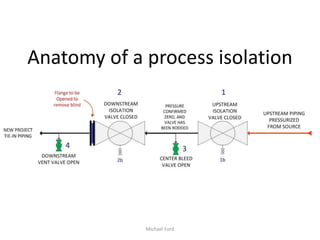
- 2. Anatomy of a process isolation Scenario: • A new project pipe section is ready to be commissioned into existing plant process piping. • A skillet blind was installed to obtain positive isolation during a project tie-in at a valve. The skillet was installed downstream of a proven double block and bleed valve isolation. This safely isolated the new section of pipe from existing live process. • The downstream work has been completed, the PSSR signed off, and now you have the task to plan the safe removal of the skillet blind, using the proven double block and bleed upstream isolation. Your task is to review the isolation and determine if it is safe for the mechanics to loosen the flange bolts to remove the blind. Michael Ford
- 3. IS THIS A SAFE ISOLATION? Michael Ford Typical isolation plan: 1. Close upstream valve 1. 2. Close downstream valve 2. 3. Open Center bleed valve 3 to vent trapped pressure and drain liquids. Close vent valve 3. 4. Ensure downstream valve 4 is open. 4. Issue permit and handover for blind removal. 5. Periodic checks that no pressure buildup at vent valve 3. 6. Begin removal of flange bolts
- 4. The answer from the Piping and Instrument Diagram view is yes, the isolation conforms to typical process isolation standards and practices. Now, let’s look at it from a mechanical view instead of the P&ID… Michael Ford
- 5. Michael Ford
- 6. Michael Ford
- 7. Does this view look different than the view from the P&ID? Michael Ford
- 8. Pressure is trapped in 3 sections within this isolation, including the flange to be opened to remove the blind Michael Ford
- 9. How much gas can actually be trapped inside of these areas? Can we just ‘crack’ open the flange slowly to vent the trapped gas? In this 24” system, the volume in the 2nd isolation valve and outlet adaptor is less than 10 cubic feet. Michael Ford
- 10. But 10 cubic feet of volume assumes atmospheric pressure, the system pressure before the isolation was 1,300 psi - That is equal to 90 atmospheres. At this pressure, 10 Actual Cubic Feet becomes almost 870 Standard Cubic Feet of wet well gas. Michael Ford
- 11. How much gas was trapped inside of 2nd isolation valve? Michael Ford
- 12. Now let’s combine the P&ID and mechanical two views and use the information to reduce hazards for this isolation and process containment flange break. Michael Ford
- 13. Michael Ford Revised isolation plan: 1. Close upstream valve 1. 2. Close downstream valve 2. 3. Open Center bleed valve 3 to vent trapped pressure and drain liquids. 4. Close vent valve 3. 5. Re-open downstream isolation valve 2. 6. Open bleed valve 3 until venting stops, then close. 7. Close downstream isolation valve 2. 8. Open cavity drain valve 2b to drain any liquids trapped in bottom. 9. Verify valve 1 integrity by monitoring bleed valve 3 for PBU. 10. Consider venting cavity 1b on upstream isolation valve 1. 11. Periodic checks that no pressure buildup at vent valve 3. 12. Issue PTW and begin removal of flange bolts. If toxic gas (H2S) N2 purge valve 2 using vent/drain body ports with valve 2 in partially open position, then re-close valve 2.
- 14. Anatomy of an isolation What were the hazards? 1. Trapped high pressure 2. Potential unexpected release of flammable gas to atmosphere in the presence of pipefitters. 3. Potential exposure to: 1. Direct blast of gas to personnel, ejected solids at high speed. 2. H2S and Benzene inhalation 3. NGLs trapped in valve start flashing off with the trapped gas release. 4. Large volume of venting, range of LEL in area 5. Ignition, tools used are spark resistant, not spark proof Michael Ford
- 15. Anatomy of an isolation What did we learn? 1. Closed Ball valves can contain a significant volume of trapped gas at high pressure. 2. Larger valve sizes and higher pressure increase the volume of the trapped gas. 3. Many valves have body vents and drains. 4. Isolation policies or procedures may not recognize these facts, and they may not be discovered during a risk assessment. Michael Ford
- 16. Anatomy of an isolation What did we learn? 5. We do not have to expose people to trapped pressure when breaking a flange, or being unaware of trapped pressure within a valve. 6. Planning an isolation requires understanding of both the process and the equipment. 7. Hidden hazards can be discovered in a risk assessment only if all the knowledge is at the table (Ops, Eng, Maint, HSE) Michael Ford
- 17. Anatomy of an isolation QUESTIONS? Find me on LinkedIn Michael Ford
Editor's Notes
- Did anyone notice any potential problems, oversights, etc?
- This example does not show cavity vent and drain valves.
- Now we see an actual picture with cavity and ball outlined over picture. Go back to cutaway to ensure everyone gets it.
- Discuss that pressure is only monitored in segment 1 (upstream plant monitoring), segment 3, and segment 6
- Point out and discuss the up and down stream sealing seats in the main valves. Both sides designed to hold full rated DP.
- Discuss how mechanical understanding of equipment is required to plan safe isolations.
- Questions?
- Questions?
- Questions?
- Questions?