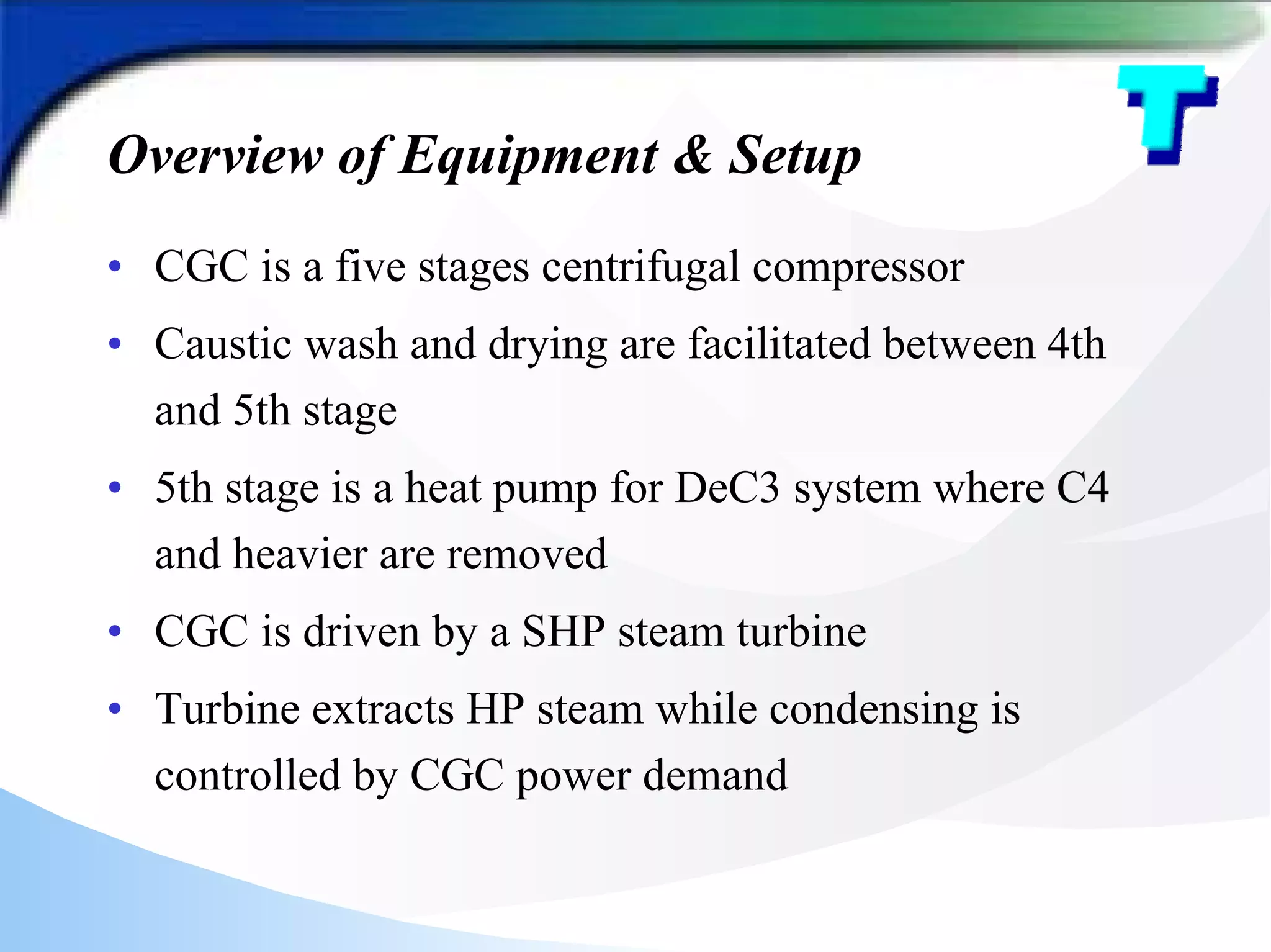
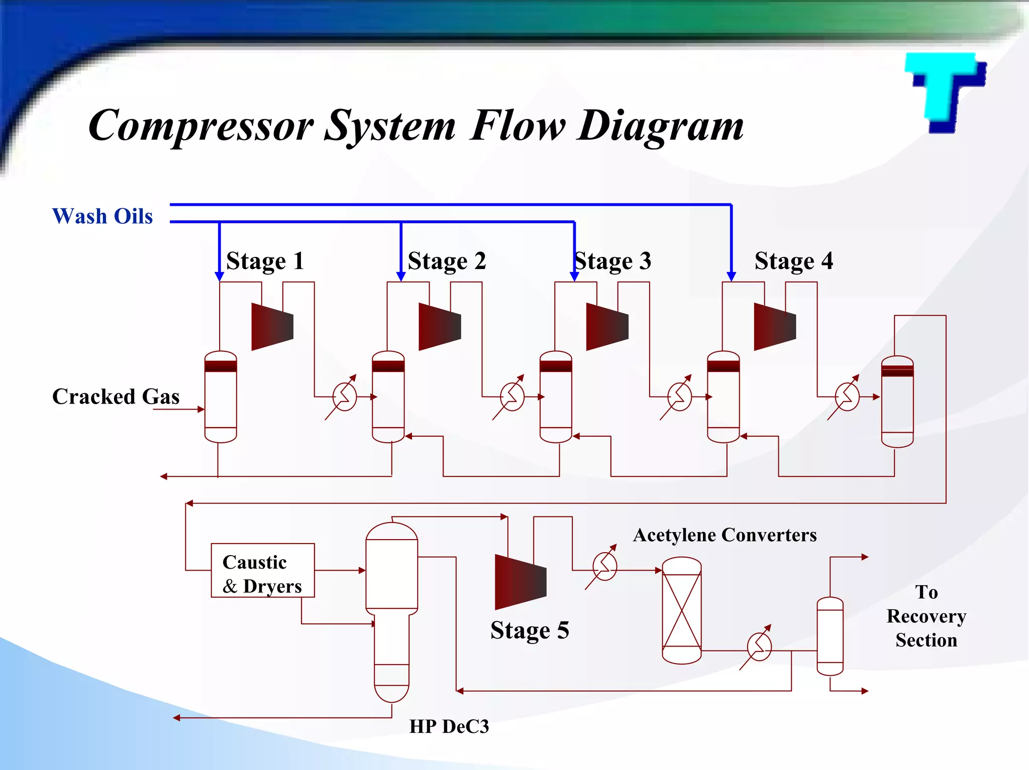
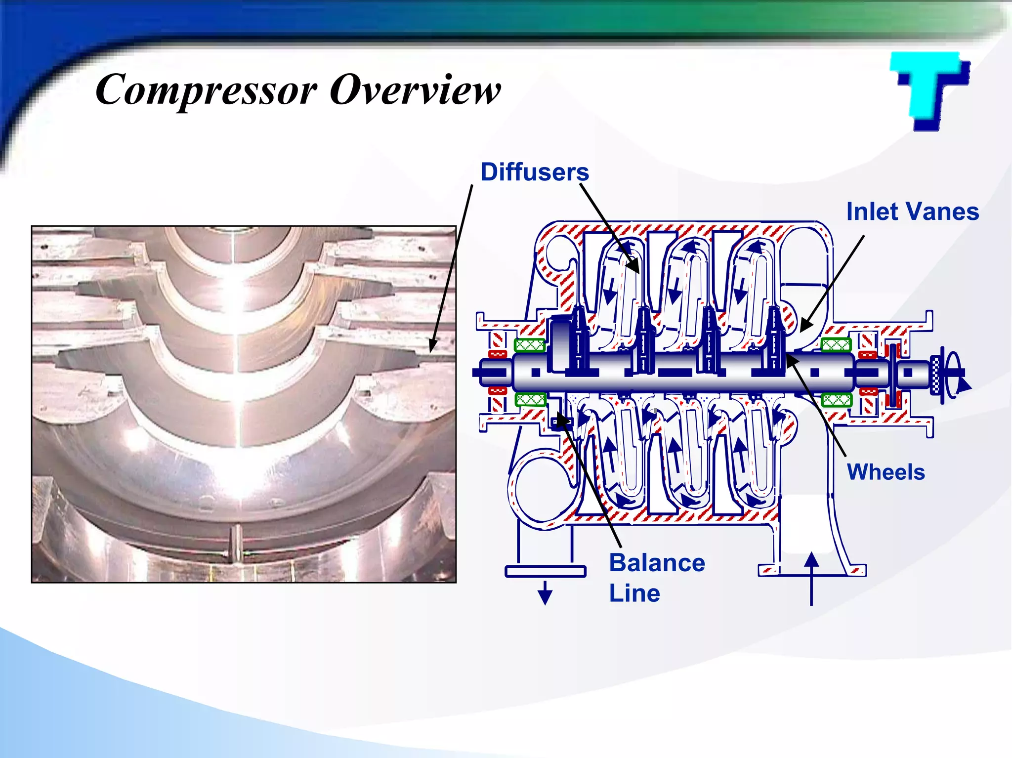
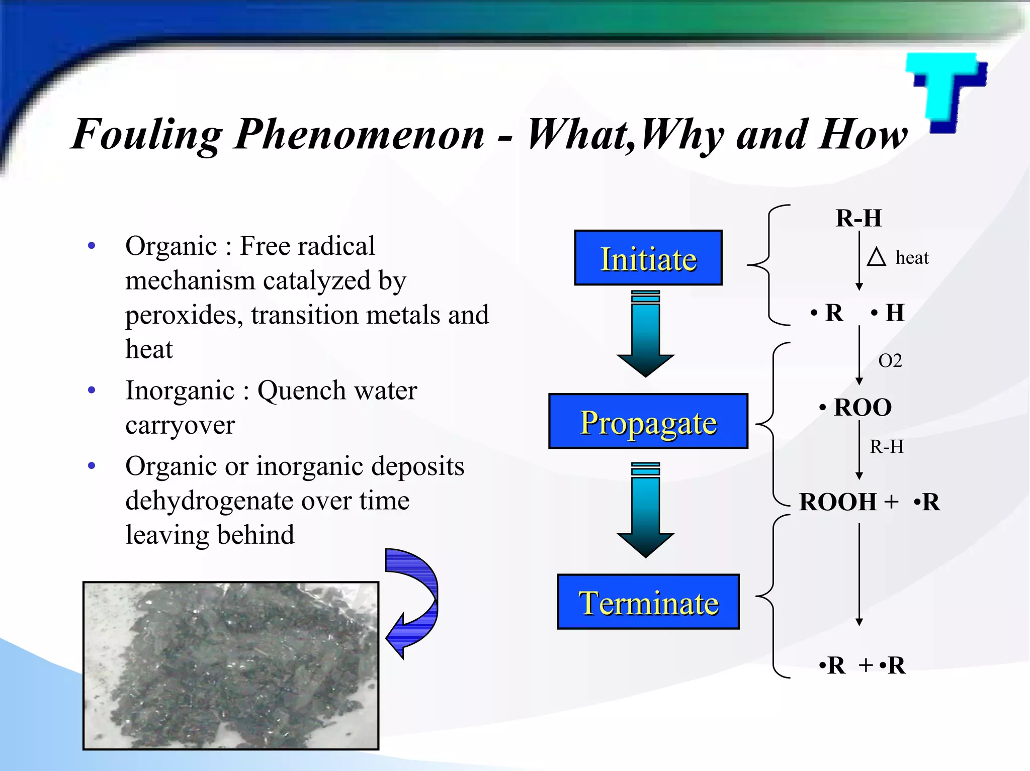
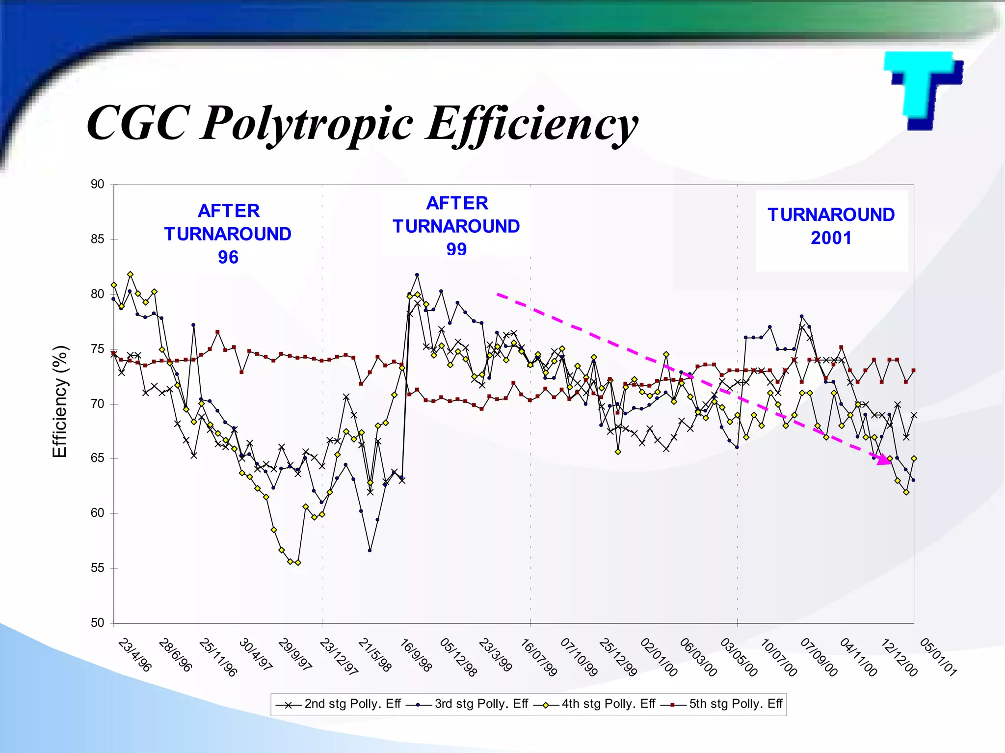
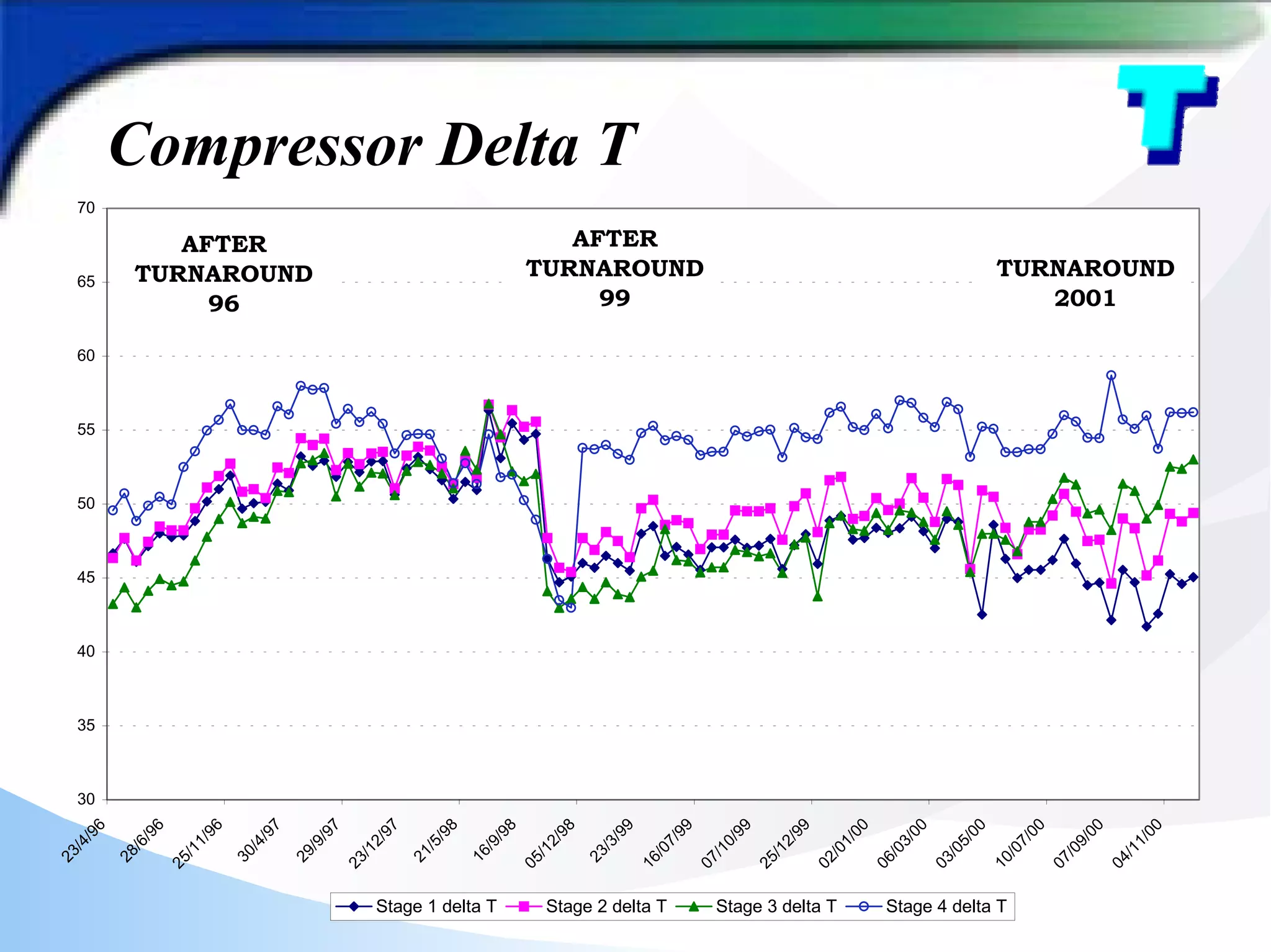
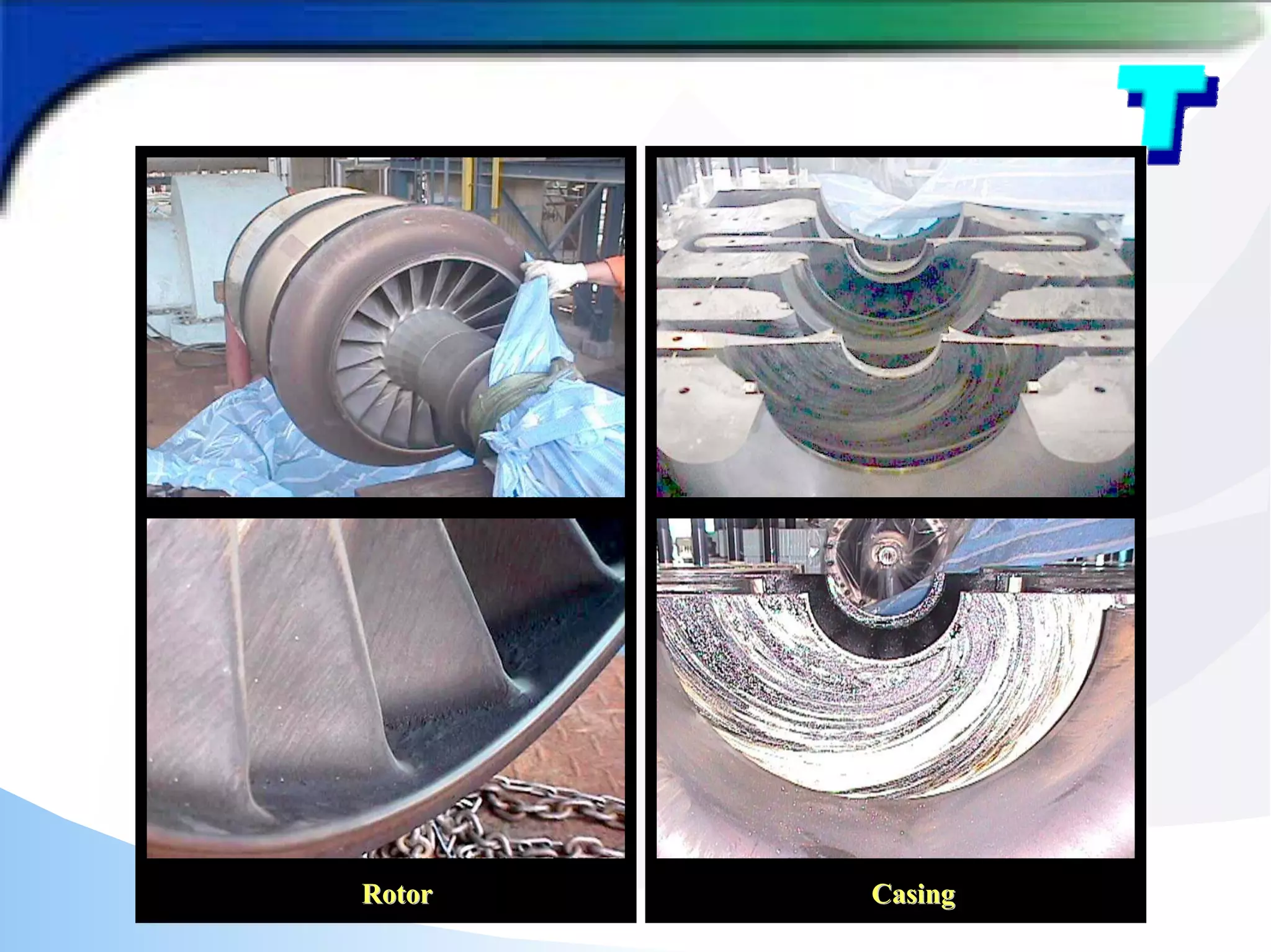
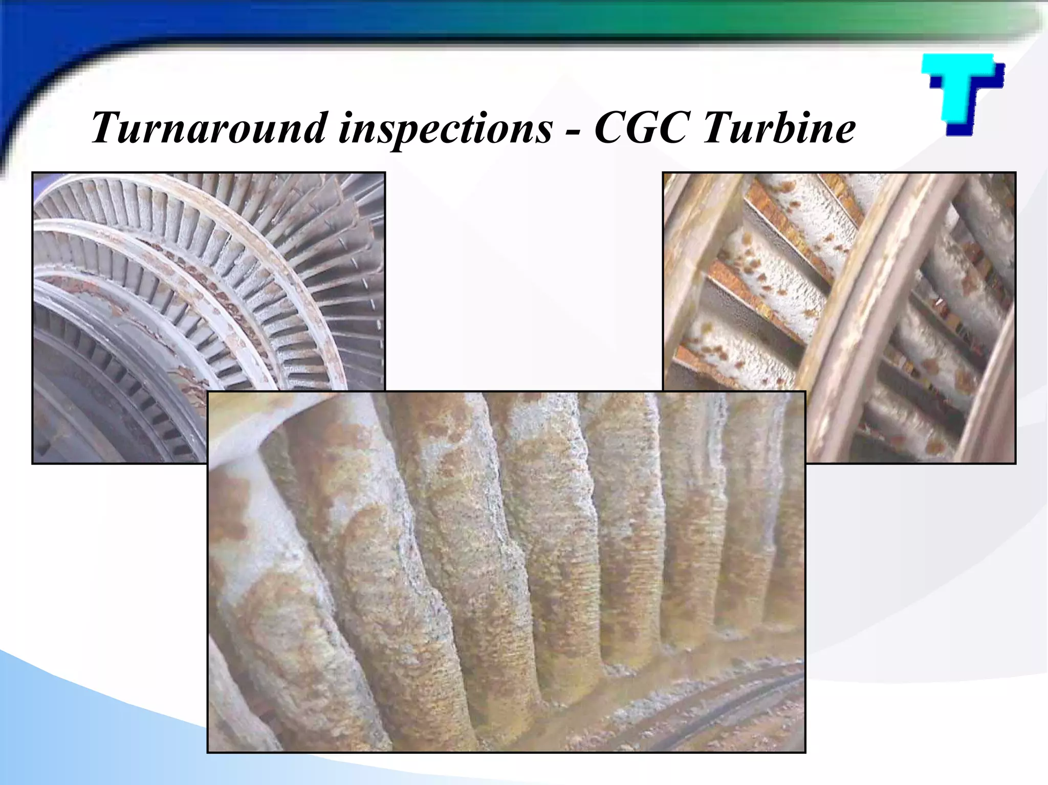
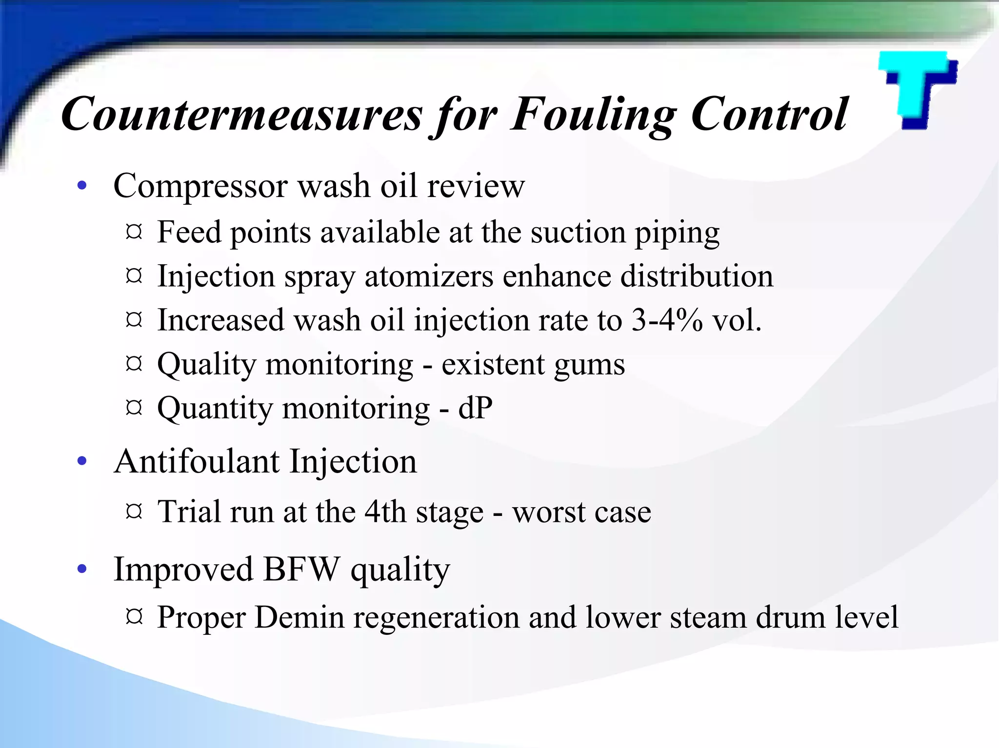
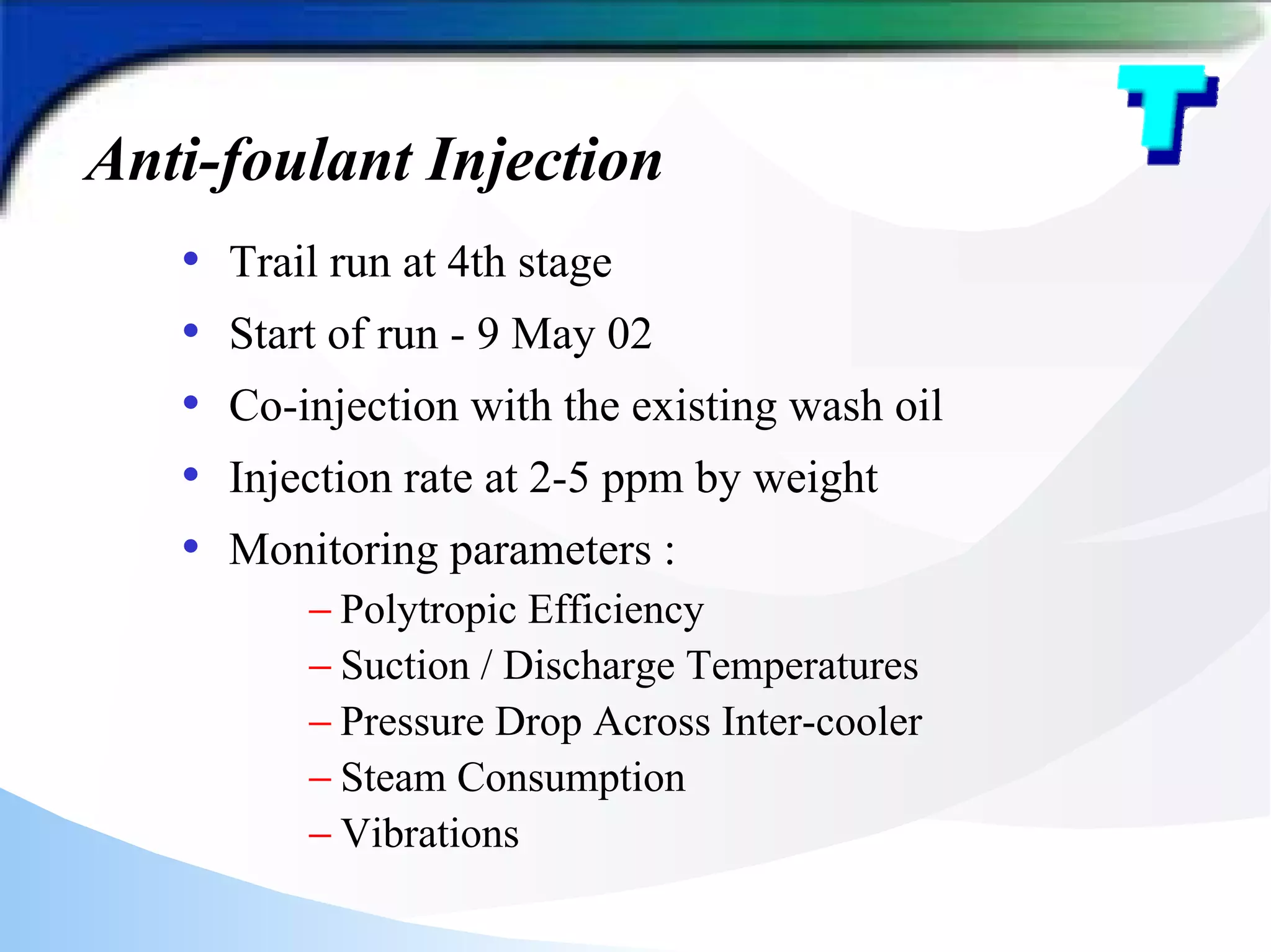
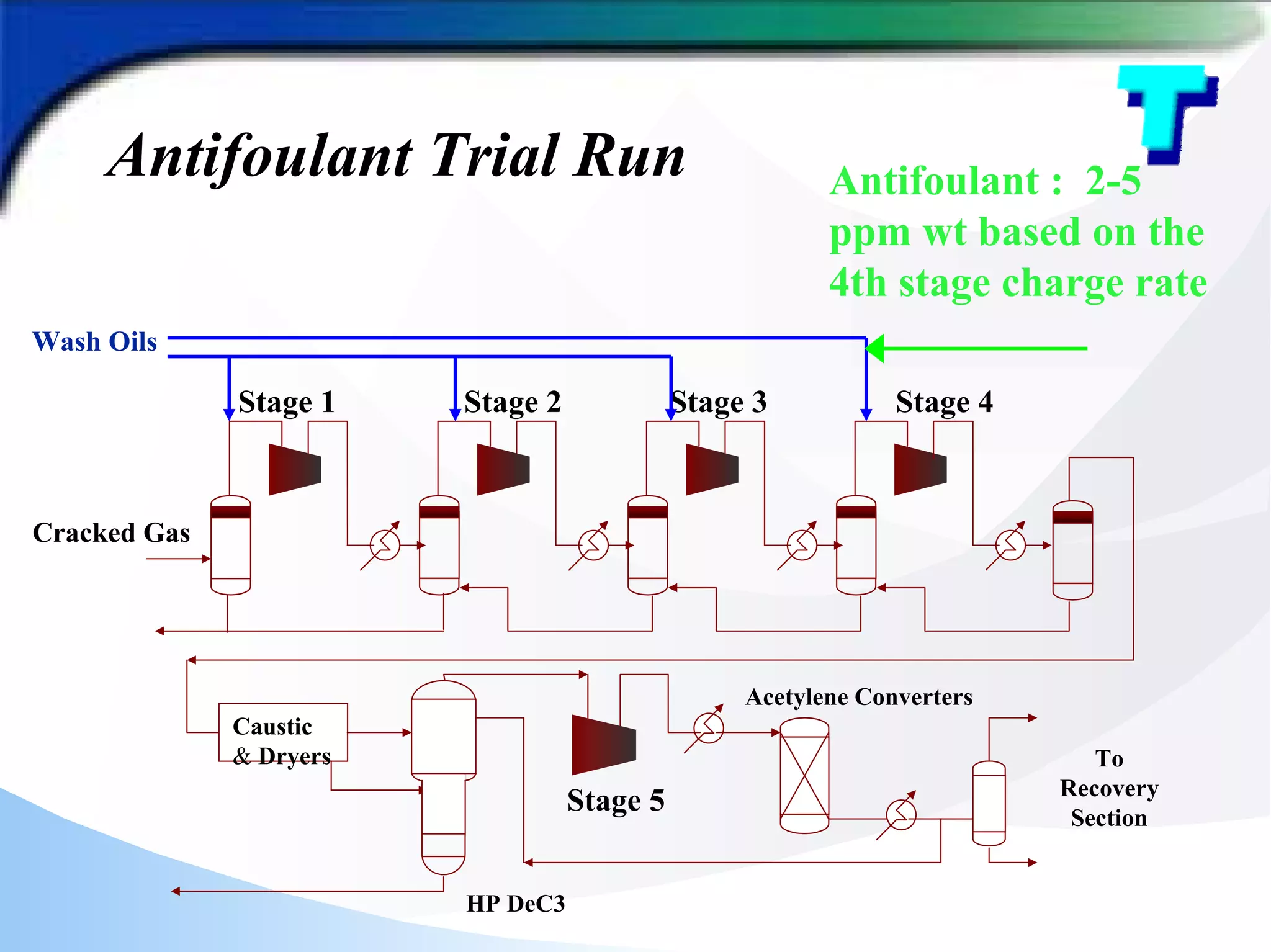
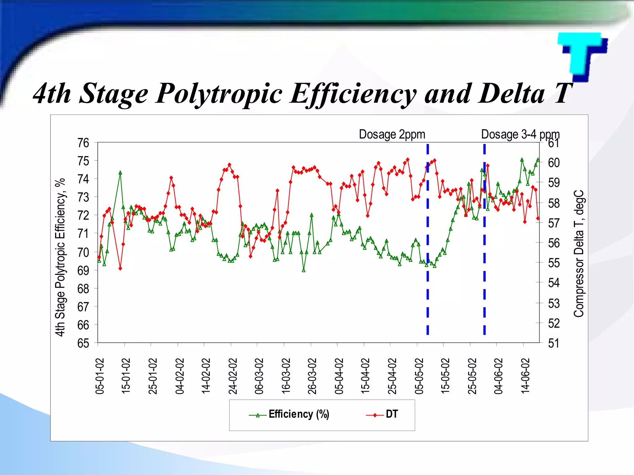
Ethylene Unit Cracked Gas Compressor
Case Studies on Fouling
Visagaran Visvalingam - Presenter
Cyron Anthony Soyza
Sew Nyit Tong
Karl Kolmetz
Outlines
? Overview of Equipment and Setup
? CGC Fouling Experiences
? Identification of Turbine Fouling
? Impacts of Compressor-Turbine fouling
? Turnaround Inspections
? Countermeasures for Fouling Control
? Future Improvements
? Conclusions
Overview of Equipment & Setup
• CGC is a five stages centrifugal compressor
• Caustic wash and drying are facilitated between 4th
and 5th stage
• 5th stage is a heat pump for DeC3 system where C4
and heavier are removed
• CGC is driven by a SHP steam turbine
• Turbine extracts HP steam while condensing is
controlled by CGC power demand
Compressor System Flow Diagram
Cracked Gas
Caustic
& Dryers
Stage 1 Stage 2 Stage 3 Stage 4
Stage 5
To
Recovery
Section
HP DeC3
Acetylene Converters
Wash Oils
Diffusers
Balance
Line
Wheels
Inlet Vanes
Compressor Overview
Fouling Phenomenon - What,Why and How
• Organic : Free radical
mechanism catalyzed by
peroxides, transition metals and
heat
• Inorganic : Quench water
carryover
• Organic or inorganic deposits
dehydrogenate over time
leaving behind
Initiate
Initiate
Propagate
Propagate
Terminate
Terminate
R-H
• R • H
• ROO
heat
O2
ROOH + •R
R-H
•R
•R +
CGC Fouling Experiences
£ Polytropic efficiencies dropped
£ Discharge temperatures increased
£ Inter-cooler pressure drops increased
£ Governor valve opening maximum
£ Turbine steam rate increased
£ Max continuos speed not sustainable
CGC Polytropic Efficiency
50
55
60
65
70
75
80
85
90
2
3
/
4
/
9
6
2
8
/
6
/
9
6
2
5
/
1
1
/
9
6
3
0
/
4
/
9
7
2
9
/
9
/
9
7
2
3
/
1
2
/
9
7
2
1
/
5
/
9
8
1
6
/
9
/
9
8
0
5
/
1
2
/
9
8
2
3
/
3
/
9
9
1
6
/
0
7
/
9
9
0
7
/
1
0
/
9
9
2
5
/
1
2
/
9
9
0
2
/
0
1
/
0
0
0
6
/
0
3
/
0
0
0
3
/
0
5
/
0
0
1
0
/
0
7
/
0
0
0
7
/
0
9
/
0
0
0
4
/
1
1
/
0
0
1
2
/
1
2
/
0
0
0
5
/
0
1
/
0
1
Efficiency
(%)
2nd stg Polly. Eff 3rd stg Polly. Eff 4th stg Polly. Eff 5th stg Polly. Eff
AFTER
TURNAROUND
96
AFTER
TURNAROUND
99
TURNAROUND
2001
Compressor Delta T
30
35
40
45
50
55
60
65
70
2
3
/
4
/
9
6
2
8
/
6
/
9
6
2
5
/
1
1
/
9
6
3
0
/
4
/
9
7
2
9
/
9
/
9
7
2
3
/
1
2
/
9
7
2
1
/
5
/
9
8
1
6
/
9
/
9
8
0
5
/
1
2
/
9
8
2
3
/
3
/
9
9
1
6
/
0
7
/
9
9
0
7
/
1
0
/
9
9
2
5
/
1
2
/
9
9
0
2
/
0
1
/
0
0
0
6
/
0
3
/
0
0
0
3
/
0
5
/
0
0
1
0
/
0
7
/
0
0
0
7
/
0
9
/
0
0
0
4
/
1
1
/
0
0
Stage 1 delta T Stage 2 delta T Stage 3 delta T Stage 4 delta T
AFTER
TURNAROUND
96
AFTER
TURNAROUND
99
TURNAROUND
2001
Identification of Turbine Fouling
? Unable to maintain speed at max steam flow
? HP and LP valve fully open
? Backpressure from LP turbine
HP
Valve
SHP
LP
Valve
P1 P2
HP Steam
Extraction
Exhaust
Steam
HP Casing LP Casing
Causes of Turbine Fouling
• BFW quality upset
– High Sodium / Silica due to capacity overrun or
improper regeneration of demin train
• Water Carry-over
– Steam drum level control high
• Steam contamination
– Attemporating water
high in sodium or silica
Water level
Impacts of Compressor-Turbine
Fouling
£ Throughput limited due to maximum driver governor
valve opening
£ Increased suction pressure
£ Energy inefficient due to higher steam rate
£ Short run length, 3 years down for cleaning
Turnaround Inspections
• Inspection done during TA99 and TA 2001
• 1st and 5th stage - relatively clean
• 2nd, 3rd & 4th stage - heavily fouled
• Polymer deposits and most samples were organic
component
• Inter-coolers fouled with polymers and tars
• Discharge piping layered with polymer
CGC Inspection- TA99 & TA2001
Summary of the Inspection Findings
Suct/Disch
piping
Impeller/
Diffuser
Volute
1st
stage
2nd
stage
3rd
stage
4th
stage
5th
stage
Turbine
1st Discharge
1st Discharge 2nd Discharge
2nd Discharge 4th Discharge
4th Discharge
3rd Discharge
3rd Discharge
1st to 4th Stage Discharge Condition during Turnaround 2000/01
Rotor
Rotor Casing
Casing
2nd stage intercooler bundle Bundle entrance
Polymer laced inlet pipeline Inlet to intercooler
Turnaround inspections - CGC Turbine
Countermeasures for Fouling Control
• Compressor wash oil review
¤ Feed points available at the suction piping
¤ Injection spray atomizers enhance distribution
¤ Increased wash oil injection rate to 3-4% vol.
¤ Quality monitoring - existent gums
¤ Quantity monitoring - dP
• Antifoulant Injection
¤ Trial run at the 4th stage - worst case
• Improved BFW quality
¤ Proper Demin regeneration and lower steam drum level
Compressor Wash Oil Review
? 1st to 3rd stage - HPG + C5
? 4th stage - HPG
? Specific gravity - 0.77-0.80
? Aromatic content - 65 %
? Existent gums - < 5mg/100ml
? Distillation D-86
– IBP - 70 oC
– End point - 185 oC
Anti-foulant Injection
• Trail run at 4th stage
• Start of run - 9 May 02
• Co-injection with the existing wash oil
• Injection rate at 2-5 ppm by weight
• Monitoring parameters :
− Polytropic Efficiency
− Suction / Discharge Temperatures
− Pressure Drop Across Inter-cooler
− Steam Consumption
− Vibrations
Antifoulant Trial Run
Cracked Gas
Caustic
& Dryers
Stage 1 Stage 2 Stage 3 Stage 4
Stage 5
To
Recovery
Section
HP DeC3
Acetylene Converters
Wash Oils
Antifoulant : 2-5
ppm wt based on the
4th stage charge rate
• Polytropic efficiency improved - 4-5%
• Comp discharge temperature reduced - 3-4oC
• Delta T reduced
• Pressure drop across inter-cooler maintained
• Vibration normal
Antifoulant Trial Run Findings
4th Stage Polytropic Efficiency and Delta T
65
66
67
68
69
70
71
72
73
74
75
76
05-01-02
15-01-02
25-01-02
04-02-02
14-02-02
24-02-02
06-03-02
16-03-02
26-03-02
05-04-02
15-04-02
25-04-02
05-05-02
15-05-02
25-05-02
04-06-02
14-06-02
4th
Stage
Polytropic
Efficiency,
%
51
52
53
54
55
56
57
58
59
60
61
Compressor
Delta
T,
degC
Efficiency (%) DT
Dosage 2ppm Dosage 3-4 ppm
4th Stage Polytropic Efficiency and Delta T
C-300 Efficiency
60
62
64
66
68
70
72
74
76
78
80
31-Mar-02
05-Apr-02
10-Apr-02
15-Apr-02
20-Apr-02
25-Apr-02
30-Apr-02
05-May-02
10-May-02
15-May-02
20-May-02
25-May-02
30-May-02
04-Jun-02
09-Jun-02
14-Jun-02
19-Jun-02
24-Jun-02
Eff,
%
2nd stage
4th stage
Ave eff = 1st to 3rd stage
Future Improvements
Wash oil quality
– C8+ High aromatics, low gums & higher FBP
– Intermittent or Continuos - 0.5% wg
– High volume flush - 2% wg
Wash oil and Antifoulant injection to casing
– Revamp or TA modification
Wash water injection
– max 1% throughput to minimize rotor erosion
Inter-coolers
– Antifoulant injection facilities for online cleaning
High efficiency 3D impeller blades (new service)
– More efficient and larger gas passage
Conclusions
? A review of equipment and maintenance records are
essential to each producer
? Part of this review should include turbine and
compressor fouling
? Adequate wash oil selection and antifoulant injection
enables cracker extension of cracked gas compressor
run lengths by reducing the amount of polymer
fouling.
? Any review should also include future optimizations
Thank You
Q & A

Ethylene Unit Cracked Gas Compressor Case Studies on Fouling.pdf

  • 1.
    Ethylene Unit CrackedGas Compressor Case Studies on Fouling Visagaran Visvalingam - Presenter Cyron Anthony Soyza Sew Nyit Tong Karl Kolmetz
  • 2.
    Outlines ? Overview ofEquipment and Setup ? CGC Fouling Experiences ? Identification of Turbine Fouling ? Impacts of Compressor-Turbine fouling ? Turnaround Inspections ? Countermeasures for Fouling Control ? Future Improvements ? Conclusions
  • 3.
    Overview of Equipment& Setup • CGC is a five stages centrifugal compressor • Caustic wash and drying are facilitated between 4th and 5th stage • 5th stage is a heat pump for DeC3 system where C4 and heavier are removed • CGC is driven by a SHP steam turbine • Turbine extracts HP steam while condensing is controlled by CGC power demand
  • 4.
    Compressor System FlowDiagram Cracked Gas Caustic & Dryers Stage 1 Stage 2 Stage 3 Stage 4 Stage 5 To Recovery Section HP DeC3 Acetylene Converters Wash Oils
  • 5.
  • 6.
    Fouling Phenomenon -What,Why and How • Organic : Free radical mechanism catalyzed by peroxides, transition metals and heat • Inorganic : Quench water carryover • Organic or inorganic deposits dehydrogenate over time leaving behind Initiate Initiate Propagate Propagate Terminate Terminate R-H • R • H • ROO heat O2 ROOH + •R R-H •R •R +
  • 7.
    CGC Fouling Experiences £Polytropic efficiencies dropped £ Discharge temperatures increased £ Inter-cooler pressure drops increased £ Governor valve opening maximum £ Turbine steam rate increased £ Max continuos speed not sustainable
  • 8.
  • 9.
  • 10.
    Identification of TurbineFouling ? Unable to maintain speed at max steam flow ? HP and LP valve fully open ? Backpressure from LP turbine HP Valve SHP LP Valve P1 P2 HP Steam Extraction Exhaust Steam HP Casing LP Casing
  • 11.
    Causes of TurbineFouling • BFW quality upset – High Sodium / Silica due to capacity overrun or improper regeneration of demin train • Water Carry-over – Steam drum level control high • Steam contamination – Attemporating water high in sodium or silica Water level
  • 12.
    Impacts of Compressor-Turbine Fouling £Throughput limited due to maximum driver governor valve opening £ Increased suction pressure £ Energy inefficient due to higher steam rate £ Short run length, 3 years down for cleaning
  • 13.
    Turnaround Inspections • Inspectiondone during TA99 and TA 2001 • 1st and 5th stage - relatively clean • 2nd, 3rd & 4th stage - heavily fouled • Polymer deposits and most samples were organic component • Inter-coolers fouled with polymers and tars • Discharge piping layered with polymer
  • 14.
    CGC Inspection- TA99& TA2001 Summary of the Inspection Findings Suct/Disch piping Impeller/ Diffuser Volute 1st stage 2nd stage 3rd stage 4th stage 5th stage Turbine
  • 15.
    1st Discharge 1st Discharge2nd Discharge 2nd Discharge 4th Discharge 4th Discharge 3rd Discharge 3rd Discharge 1st to 4th Stage Discharge Condition during Turnaround 2000/01 1st to 4th Stage Discharge Condition during Turnaround 2000/01
  • 16.
  • 17.
    2nd stage intercoolerbundle Bundle entrance Polymer laced inlet pipeline Inlet to intercooler
  • 18.
  • 19.
    Countermeasures for FoulingControl • Compressor wash oil review ¤ Feed points available at the suction piping ¤ Injection spray atomizers enhance distribution ¤ Increased wash oil injection rate to 3-4% vol. ¤ Quality monitoring - existent gums ¤ Quantity monitoring - dP • Antifoulant Injection ¤ Trial run at the 4th stage - worst case • Improved BFW quality ¤ Proper Demin regeneration and lower steam drum level
  • 20.
    Compressor Wash OilReview ? 1st to 3rd stage - HPG + C5 ? 4th stage - HPG ? Specific gravity - 0.77-0.80 ? Aromatic content - 65 % ? Existent gums - < 5mg/100ml ? Distillation D-86 – IBP - 70 oC – End point - 185 oC
  • 21.
    Anti-foulant Injection • Trailrun at 4th stage • Start of run - 9 May 02 • Co-injection with the existing wash oil • Injection rate at 2-5 ppm by weight • Monitoring parameters : − Polytropic Efficiency − Suction / Discharge Temperatures − Pressure Drop Across Inter-cooler − Steam Consumption − Vibrations
  • 22.
    Antifoulant Trial Run CrackedGas Caustic & Dryers Stage 1 Stage 2 Stage 3 Stage 4 Stage 5 To Recovery Section HP DeC3 Acetylene Converters Wash Oils Antifoulant : 2-5 ppm wt based on the 4th stage charge rate
  • 23.
    • Polytropic efficiencyimproved - 4-5% • Comp discharge temperature reduced - 3-4oC • Delta T reduced • Pressure drop across inter-cooler maintained • Vibration normal Antifoulant Trial Run Findings
  • 24.
    4th Stage PolytropicEfficiency and Delta T 65 66 67 68 69 70 71 72 73 74 75 76 05-01-02 15-01-02 25-01-02 04-02-02 14-02-02 24-02-02 06-03-02 16-03-02 26-03-02 05-04-02 15-04-02 25-04-02 05-05-02 15-05-02 25-05-02 04-06-02 14-06-02 4th Stage Polytropic Efficiency, % 51 52 53 54 55 56 57 58 59 60 61 Compressor Delta T, degC Efficiency (%) DT Dosage 2ppm Dosage 3-4 ppm
  • 25.
    4th Stage PolytropicEfficiency and Delta T C-300 Efficiency 60 62 64 66 68 70 72 74 76 78 80 31-Mar-02 05-Apr-02 10-Apr-02 15-Apr-02 20-Apr-02 25-Apr-02 30-Apr-02 05-May-02 10-May-02 15-May-02 20-May-02 25-May-02 30-May-02 04-Jun-02 09-Jun-02 14-Jun-02 19-Jun-02 24-Jun-02 Eff, % 2nd stage 4th stage Ave eff = 1st to 3rd stage
  • 26.
    Future Improvements Wash oilquality – C8+ High aromatics, low gums & higher FBP – Intermittent or Continuos - 0.5% wg – High volume flush - 2% wg Wash oil and Antifoulant injection to casing – Revamp or TA modification Wash water injection – max 1% throughput to minimize rotor erosion Inter-coolers – Antifoulant injection facilities for online cleaning High efficiency 3D impeller blades (new service) – More efficient and larger gas passage
  • 27.
    Conclusions ? A reviewof equipment and maintenance records are essential to each producer ? Part of this review should include turbine and compressor fouling ? Adequate wash oil selection and antifoulant injection enables cracker extension of cracked gas compressor run lengths by reducing the amount of polymer fouling. ? Any review should also include future optimizations
  • 28.