
Recommended
Recommended
More Related Content
What's hot
What's hot (20)
Viewers also liked
Similar to Icpa abstract id 2062 (full paper)v1.1
Similar to Icpa abstract id 2062 (full paper)v1.1 (20)
Recently uploaded
Recently uploaded (20)
Icpa abstract id 2062 (full paper)v1.1
- 1. Developing UAV image acquisition system and processing steps for1 quantitative use of the data in precision agriculture2 3 A. B. Tekin1, M. Fornale24 5 1Agricultural Engineering & Technology Department6 Ege University7 İzmir,Turkey8 behic.tekin@ege.edu.tr9 2AgriculturalUav.ue Project10 Istanbul, Turkey11 mfornale@agriculturaluav.eu12 13 14 ABSTRACT15 16 Mapping natural variability of crops and land is first step of the management17 cycle in terms of crop production. Several methods have been developed and18 engaged for data recording and analyzing that generate prescription maps such19 as yield monitoring, soil mapping, remote sensing etc. Although conventional20 remote sensing by capturing images via satellites has been very popular tool to21 monitor the earth surface, it has several drawbacks such as orbital period,22 unattended capture, investment cost. On the contrary, unmanned air vehicle23 (UAV) is more flexible in terms of deploying, monitoring small area and easy24 to acquire at low cost.25 In this aspect, the objective of this study was to develop a low-cost and easy to26 implement technical solution to map spatial variability, and to explore its27 relationship with crop conditions. The idea was to build a close loop process28 starting from a standardized UAV based image shooting till an easy but29 reasonable production of NDVI and derived/prescription maps especially for30 vineyards.31 The main components of this image acquisition system are Unmanned Air32 Vehicle (UAV) and modified commercial digital camera. Within the study, 333 different UAV (2 fixed wings and one flying wing) have been built, based on34 commercial airplanes models fitting the purpose and used open source35 autopilot. As sensors, 2 small format digital cameras (1 Nikon and 1 Canon)36 have been tested, part of them modified in order to be able to acquire also NIR37 radiations.38 Laboratory tests were conducted in order to calibrate the cameras. After all,39 UAV based image acquisition system was developed. Future tests were40 planned for the assessment of practical usage in situ.41 42 Keywords: UAV, sensor, precision agriculture43 44 45 INTRODUCTION46 47 For last few decades, precision agriculture and its technologies have been48 considered being the most significant development in agricultural sector49 targeting management of natural heterogeneity to improve farm profitability,50
- 2. to minimize negative load on environment and to comply agronomic1 requirements (Tekin and Yalçın, 2014).2 The new approach utilizes detailed records of whole farm operations that3 require technological tools in order to save automatically generated data.4 Moreover, the improvement of natural heterogeneity management is a primary5 mission of precision agriculture by processing the data. The philosophy of6 precision agriculture is “applying the right thing, at the right time, on the right7 location, with right methods and with the minimum negative load on the8 environment”.9 In order to comply with the philosophy, the sensing and gathering data is a10 key element since it is the first step of determination of variability (Fig 1).11 Several methods and tools such as remote sensing, spectral and hyperspectral12 camera have been developed for 30 years.13 14 15 16 Fig 1- The cyclical process of precision viticulture17 18 Remote Sensing19 20 Objects reflect off light coming from the sun or artificial sources. Light is21 consists of electromagnetic spectrum those certain wavelengths (380- 700 nm)22 of it can be seen with human eye. However, large scale of electromagnetic23 spectrum is not visible for naked eye. Previous researches revealed that each24 objet has unique spectral signature which is the difference in the25 reflectance/emittance characteristics with respect to wavelengths (i.e.,26 reflectance/emittance as a function of wavelength). Spectral characteristics of27 objects, in this case crops, soil and etc. are an information source for28 determination of variability.29 Satellite and airborne imaging systems capture the sunlight reflecting from30 ground objects by their sensors. This type of tools allow user to capture the31 images on demand and to cover large area. However, several drawbacks still32 exist and prevent to obtain clear images such as cloud and atmospheric haze.33 Recently, unmanned air vehicle has been promise in civil use although it34 was developed for military purpose. The platform has been used in civil life;35 Surveying mapping, civil infrastructure, mine exploration, precision36 agriculture and etc. Due to many advantages and closing the gap arising from37 conventional remote sensing, unmanned air vehicle is getting attractive.38 Several commercial UAV platforms and sensing tools have been on the39 market with quite expensive cost. On the other hand, it is well known that40 farmers cannot generate sufficient cash easily and invest new technologies that41
- 3. limit the penetration of them. Therefore, the cheapest and affordable tools are1 required.2 The stated objectives of the project are;3 to develop a low-cost and easy to implement technical solution to map4 spatial variability, and to explore its relationship with crop conditions5 to build a close loop process starting from a standardized UAV based6 image shooting till an easy but reasonable production of NDVI and7 derived/prescription maps8 finally to have a tool for PF giving good quality result without9 investing enormous amount of money10 11 Material and Method12 13 The main components of the proposed image acquisition system were14 Unmanned Air Vehicle (UAV) and modified commercial digital cameras.15 16 UAV Platforms:17 18 Within the study, 3 different UAV (2 fixed wings and one flying wing)19 have been built, based on commercial airplanes models fitting the purpose and20 used open source autopilot (Fig 2). The models are equipped with APM 2.5,21 APM 2.6 and APM 2 model ardupilot (open source autopilot, based on22 Arduino and equipped with Arduplane firmware) respectively supplied from23 3D Robotics (USA).24 25 26 (a) Phantom Fx-61 (b) EPP-FPV HK27 28 29 (c) SkyWalker 190030 31 Fig 2- The UAV platforms32 33 34
- 4. Cameras for image capturing:1 2 Typically most chlorophyll-containing vegetative surfaces reflect strongly3 in the green side of the spectrum (≈ 530 nm) while have low reflectance4 (associated with strong chlorophyll absorption) in the blue and red side.5 Therefore, photosynthesizing objects appear green when viewed in visible6 portion only. On the other hand, a higher proportion of the sunlight is reflected7 in the near infrared band of the electromagnetic spectrum (Campbell, 1996).8 Measurement of near infrared reflectance is an important method of9 delineating relative amounts of plant biomass. It has been also revealed that10 the near infrared reflectance of vegetation is more sensitive to changes in plant11 health than in the visible portion of the spectrum (Campbell 1996). In this12 case, the influence of vine diseases, pests, nutrition and available moisture will13 affect vine biomass therefore leaf spectral characteristics.14 Spectral vegetation indices (NDVI, VI, GNDVI, LAI and etc.) which15 utilize the significant differences in reflectance of vegetation at green, red and16 near infrared wavelengths allow monitoring health and development of17 vineyards.18 Therefore, within the project, 2 small format digital cameras (1 Nikon and19 1 Canon) have been tested and part of them modified in order to be able to20 acquire also NIR radiations (Fig 3). The spectral sensitivity of the cameras21 without hot-mirror filter was measured using monospectral calibrated light22 source from Specord 50 MonoChromator (400 – 1060 nm step 20 nm) (Fig 4)23 24 .25 26 27 28 (a) Nikon Coolpix P6000 (b) Canon IXUS 13229 30 Fig 3- The Cameras for image capturing31 32
- 5. 1 2 Fig 4- Measuring spectral response of CCD Camera3 4 When the internal hot-mirror filter is removed and a blue-blocking filter is5 placed in front of the lens, Bobbe et al. (1995) found that the blue channel6 records the NIR light reflected from vegetation. In calibration process, the7 contributions of NIR light to the digital numbers of the green and red channels8 were subtracted based on the value from the blue channel. Therefore, with9 extensive post-processing, the raw digital camera image has been converted10 into a red, green and NIR false-color image.11 The image acquisition on the cameras was done using external triggers12 (infrared or autopilot driven contact) and can be activated through the operator13 remote control on the ground or programmed to be automatically done using14 either a dedicated feature of the autopilot board (based on GPS or regular15 interval) or intervallometer scripts at camera's firmware level.16 At an altitude of 150-200 m, this system acquires images with a ground17 resolution of 6 cm for the visible and near infrared bands. Unmanned Aerial18 Vehicle common altitude stretches over several tenths of meters up to 500 m19 and is adapted to the survey of fields of several hectares with very high spatial20 resolution.21 Geometric and radiometric processing is necessary on images for22 quantitative use of the data. Therefore, all images were taken in raw format for23 both camera types. The images were preprocessed and corrected especially for24 vignetting effect present on the modified cameras and particularly visible in25 NIR band. Classical photogrammetric calibration was used in order to measure26 lens geometry of each camera and evaluate as precisely as possible the27 coefficients of the lens polynom needed by commercial photogrammetric28 software. Several sets of images were acquired over experimental fields. These29 images were radio metrically and geometrically corrected used the above30 elements and are stored as georeferenced images in Agisoft Photoscan31 software (Russia). The images were compensated for different atmospheric32 and illumination conditions in the image time series by using invariant targets33 on the field.34 35 Results36 Development of technical solution:37 Within the project it was aimed to develop a low-cost and easy to38 implement technical solution to map spatial variability. Therefore, it was39
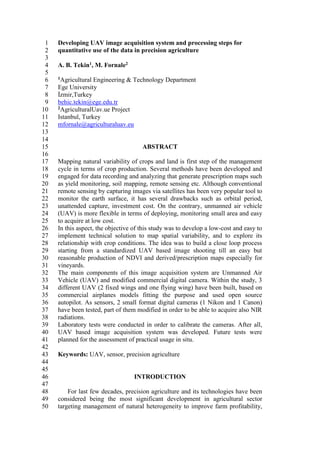
- 6. proposed to build UAV platform for carrying the image capturing tools at low1 cost. After receiving parts of the UAV from several suppliers, the platforms2 have been built in laboratory condition (Fig 5). The platforms can be3 controlled either by remote control unit or autopilot. After assembling parts4 such as wing, tail to build UAV body, electronic parts (control unit, battery,5 radio link, servo controllers and etc.) were installed. The body parts made of6 EPO foam structure that allow in case of crash to fix the damaged parts in less7 than 30 minutes and continue shooting the pictures. EPO foam airplanes are8 light, less dangerous and easy to repair in the most cases. The communication9 link was established with RC and flied in outdoor successfully.10 11 Fig 5- Assembled structure of Skywalker 1900 and initial outdoor test12 13 After teaching the flying ability of UAV to autopilot, simple mission was14 completed successfully in open area. All tests were done in order to optimize15 the sensor settings and training the UAV autopilot.16 In order to have cheap solution for capturing image, digital cameras were17 modified. It was tested if the camera could capture invisible portion of the18 spectrum. After measurement, the data was processed in excel and graphed in19 order to obtain the performance. The modified camera is a capable of sensing20 the wavelengths in a range of 380 – 1060 nm. That allows capturing NIR band21 (Fig 6).22 23
- 7. 1 Fig 6- Spectral response of CCD Camera2 3 NDVI calculation was based on previous research (Volker Dworak ,2012)4 and adapted to the spectral response of the selected camera:5 6 NDVI = ((1.4*b3-b1)/b1)*((1.4*b3)/2)7 8 Where b3= Blue Channel, b1 = Red Channel – please note that in case of9 single chip camera without hot mirror, b1 = NIR+Red10 11 Development of NDVI maps:12 In order to reveal the ability of proposed technological solution, all field13 tests was carried out in viticulture parcels in Denizli, Turkey (Fig 7)14 manageding by Sevilen Group in collaborationwho carried out also basic15 ground trothing survey. (Fig 7).16 17 18 19 Fig 7- Mission flight on viticulture parcels in Denizli, Turkey20 21 The images were captured during the mission flight and processed to22 obtain ortophoto and overlapped over google earth (Fig 8).23 24
- 8. 1 2 Fig 8- Ortophoto and overlapping on google earth map3 4 In order to have clear vision from the map, several post processing and5 false colors palette were applied. The blue on the processed map resemble low6 vigour, red resemble high vigour of the vegetation (Fig 9). Although, the result7 was not used in field, but gave an idea of the problematic parts. From the8 analisys of these maps it is understood that higher number of pictures have to9 be combined together in order to smooth indirect sun light reflectance.10 Hovewer, this first study is fundamental for having the chance to meet with11 target.12 13 14 15 16 Fig 9- NDVI map of viticulture parcels17
- 9. 1 Cost of the solution:2 Total system cost was aprroxiamlety $ 1600 that includes UAV3 (SkyWalker 1900 in use at University) and modified camera (Canon Ixus4 132), is easliy affordable. To have a clear idea, the cost could be compared5 with the price of a basic spectral camera for UAV only, that is around $3500.6 7 Conclusions8 Within the study, low-cost and easy to implement technical solution to9 map spatial variability was developed. The system was tested to explore10 relationship with crop conditions by using NDVI indices for viticulture. It was11 revealed that the solution is capable of generating prescription maps for12 precision viticulture more generally for precision agriculture. Further studies13 will be carried out to verifyobtain actual results with agronomist support.14 Acknowledgement15 The project is funded by scientific research projects divison of Ege16 University. Authors would like to thank ION+AgriculturalUav.eu (İstanbul,17 Turkey) for its support on building technological solution and Sevilen Group18 (İzmir, Turkey) for its support at field test stage.19 20 21 References22 1- Agisoft Photoscan (2015). Photogrammetric processing of digital23 image software. http://www.agisoft.com/24 2- Bobbe, T.; McKean, J.; Zigadlo, J.P. (1995). An evaluation of natural25 color and color infrared digital cameras as a remote sensing tool for26 natural resource management. In Airborne Reconnaissance XIX;27 Fishell, W.G., Andraitis, A.A., Henkel, P.A., Eds.; SPIE: Bellingham,28 WA, USA, 1995; Volume 2555, pp. 151-157.29 3- Campbell, J. B. (1996). ‘Introduction to remote sensing.’ (The Guilford30 Press: London.)31 4- Dworak V., Selbeck, J., Dammer, K.H., Hoffmann, H., Zarezadeh,32 A.A., and Bobda, C. (2012). Strategy for the Development of a Smart33 NDVI Camera System for Outdoor Plant Detection and Agricultural34 Embedded Systems35 5- Tekin, A.B., Yalçın, H. (2014). Development of online soil profile36 sensor for variable depth tillage. Proceedings of the 12th International37 Conference Precision Agriculture. Sacramento, ABD.38 39 40 41