National green building code 2021 india kaya kool hey hum by link vue system

National Building CODE 2021 by Bureau of Energy Efficiency (Ministry of Power, Government of India to ensure Utilization of Power by Building and Infra with use of Automation Help Monitor , Controls and Networking to easy and freedom to know and control their Electrical and Electronics using Mobile/TAB if they are away from their Facilities. To Support Carbon Free Green Environment Installation of Solar PV Power and High Energy Battery Storage establish Electrical Vehicle Charging in every Large Building and Housing Society Compulsory with ensure 25% free and Reserve Parking for Electric Vehicles . Rating for Green Building Start from Power Supply Incomer Transformers, Low Voltage Power Distribution Controls Panels and Supply to all Building ,Flats using Power Distribution Junction BOX installation of Surge Protection and RCD with Load and Application base type of MCB's. For Networking maximum installation and Laying of Fiber Cable and Turn to Electrical when enter into premises Indoor ,this help to protection for Surge threat any because of Lighting Discharge and may be chance to enter into System by Power Line or through Communication Cables. Maximum Product which we use in our Building should be 5 Start Rating (Energy Efficient Products) along with possible to Connect to IBMS. The Circular issued by Ministry of Power and Bureau of Energy Efficiency to CPWD/PWD/Project Engineering Division Center and State with advise to Architects ,Electrical, MEP Consultants to implements without fail these Advise for all upcoming new Buildings Infra for Government and Large Private Infra Project , Metro Station Building , Depot ,Railway Station Building , Hospitals,Universities, Airports Infra along with who want to have Green Building and Star Rating for Buildings. Plz go through presentation to know more about us visit webpage www.linkvuesystem.com Link Vue System Offer Components , Design , Engineering Selection of Right and Genuine Products , Supply of BOQ extend support for Installation. Smart Data Logger , RTU's ,Protocol Converter BACNet .Modbus RTU, MODbus TCIP, Ethernet , Lon-works , IEC61850. Networking LAN,Fiber ,Wireless , GSM Solution Protocol to Fiber Optic Converter CCTV ,Fire Alarm,Access Controls,Security Systems Building Electrical Free Connectors Industrial Plug Sockets EV Connectors and Harness EV Charger 3 KW-300 KW AC /DC Public Chargers Plz send for Web presentation /Inquiry Mail to manav.chandra@linkvuesystem.com M-9811247237

Recommended
Recommended
More Related Content
What's hot
What's hot (20)
Similar to National green building code 2021 india kaya kool hey hum by link vue system
Similar to National green building code 2021 india kaya kool hey hum by link vue system (20)
More from Mahesh Chandra Manav
More from Mahesh Chandra Manav (20)
Recently uploaded
Recently uploaded (20)
National green building code 2021 india kaya kool hey hum by link vue system
- 1. National Green Building Code 2021 India Kaya Kool Hey HUM
- 3. Link Vue System Pvt Ltd ElectricalSafety Earthing,Lightning & Surge Protection Net Working Product Supply & Installation Ethernet SW, Fiber Optics & Wire Less Automation Products Data Logger, RTU's Digital & Analog 1/0's Protocol Converter, Media Converter, Cables Connectors & LIU's Perimeter Intrusion Detection System CCTV, Fire Alarm, Access Controls & Security System Cable & Connectors, Plug & Sockets for Electrical Vehicles, Solar PV, Building Wiring I N D I A A U S T R A L I A
- 4. Link Vue System Offer Safety for Human and Assets (ALERT 24X7)
- 6. With Link Vue Freedom to Monitor,Access and Control Remotely
- 7. We Mind Your Safety First All Solution for Buildings
- 9. Building Automation and Control Systems BACS has become and will continue to be increasingly common in the built environment, converging many diverse building systems as computing technology developed and connectivity became more available. Section 3 introduces the premise of Building Automation and Control Systems (BACS), including the many terms used such as Building Automation Systems (BAS), Building Management Systems (BMS), Building Energy Management System (BEMS), Intelligent Buildings (IB) and increasingly, Smart Buildings and even Smart Cities. (An automated system,where building services and processes, communicate with each other to exchange digital, analogue or other forms of information, to a central control point)
- 12. 24X7 Smart Power for All
- 13. High Energy StorageBattery Offer Long Duration Power Supply(DEMAND)
- 14. Solar PV Power and Electric Car Charging with Parking
- 15. Smart Home Energy Management System(SHEMS)
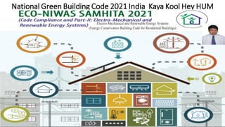
- 18. Eco Niwas Samhita 2021 for All Purpose Building
- 20. Smart Home Energy Management System (SHEMS) • The concept of smart home is in existence for many decades; however, it has gained further importance in present scenario due to increase in demand for comfort and convenience (with growth of disposal income), increased dependence on appliances, increase in per capita electricity consumption and availability of rooftop solar PV and EV for potential onsite generation and storage respectively. Alongside these drivers at consumer end; technology advancement in the form of availability of high speed computing devices (smart phones) and affordable internet data, reduction in size of IoT devices / sensors and by shifting sophisticated computing functions to cloud and development of complex algorithms to control systems as per user requirement and preference (using Artificial Intelligence) has provided fresh push to demand of smart home product and services. The need of utility-based demand response program to match the variable consumer demand (due to use of diverse appliances) with dynamic electricity supply (due to penetration of renewable energy in grid) is gradually making the smart home solutions a must have product/service in every home, to make it demand response ready. • To manage the energy use in a home in order to make optimum use of these opportunities and for minimizing the demand supply gap, there is need of Smart Home Energy Management System (SHEMS). SHEMS can be defined20 as the combination of a service and devices that are designed to work together to deliver occupancy-based optimization of energy use. SHEMS21 consist of hardware and software, which are linked and integrated to, monitor energy usage, provide feedback on energy consumption, enhance control and provide remote access and automation provisions over appliances and devices that use energy in the home. SHEMS can deliver a range of services and benefits to households, which includes: • Energy management (energy efficiency) • Demand response (contribute to regulating energy demand) • Electricity generation, storage and delivery to the grid • Comfort and convenience • The functionality of SHEMS can be broadly categorized in five areas that include monitoring, control, user interface, data sharing and grid connectivity. Schematics indicating the functionality of SHEMS and purpose of each functionality is given below:
- 21. Smart Home Energy Management System(SHEMS) The above-mentioned functionalities of SHEMS22 can be operationalized with the support of: Physical sensors and devices,Communication network for data transfer across smart devices, computation and data storage systems ,Data processing, decision making and relay commands as per defined logic or preference ,Smart appliances, devices and actuators to align the physical parameters to required level User interface to enable user to monitor, interact with smart home components and convey preferences Smart meter to monitor, record the energy consumption, load variation and to facilitate implementation of demand response program Smart home, energy and cost savings is achieved by: Preventing idle running of energy consuming system,Optimization of adjustable building envelope elements to minimize energy demand Optimization of operating parameters to match user preference,Shifting the operation of non-essential energy consuming systems to off peak timeMaking use of renewable energy generation source, whenever available to meet the energy demand,Optimization of charging and discharging of storage for cost saving Smart home have significant potential for saving energy, however, the net energy savings depends on a range of factors, which include: The rationale behind automation (comfort or energy saving),Level and type of automation used (i.e. occupancy based on/off control or fine tuning of operating parameters based on user preference and weather conditions),User behaviour (whether the user just looks at energy monitoring information or uses this information to change settings or change behaviour),Power consumption by monitoring and control devices,Additional power consumption by appliances in standby mode due to inclusion of smart communication features.. To ensure availability of minimum capabilities (regarding monitoring, control, user-interface, data sharing and grid connectivity) and to successfully deliver basic smart home experience to user, a minimum set of smart home devices should to be installed in a home.
- 22. Smart Home Energy Management System(SHEMS)
- 24. Street Light LED
- 25. Street Light LED
- 26. Fiber Optics Cables,Connectors and LIU’s
- 27. Fiber Optic Cable Network Architecture
- 28. Your Best Partner for Solution Data Communication & Networking
- 30. Safe Alarmand Secure Action Level
- 31. With Link-vue Freedom to Monitor ,Access and Control Remotely
- 32. I am Power Plug I will be Marry with only My Right Partner Make you Safety and Comfort
- 34. Electrical Power Socket IP Protection Outdoor
- 35. Electrical Socket for Indoor and Out Door Purpose
- 39. Electrical PLUG & Socket High Voltage IP 68
- 40. Electrical PLUG &Socket High Voltage IP 68
- 41. Electrical Plug & Socket High Voltage IP 68
- 42. Solar PV and EV Connectors /Harness
- 43. EV Connectors and Cabels
- 44. IP 68 Flame Froof Junction Box Plastic Material
- 45. Metal Junction Box Out Door
- 47. Electrical Safety First to Safe Human and Assets
- 50. I should Design Electrical Installation to Perform My Equipment and Safety of Mine and Other’s from Electrical Shocks Earthing Design is Not a BOQ It’s Design New Every Installation Depend on Soil Report Earthing Value should be Achive and Maintained 24X7 365Days
- 51. Link Vue System Electrical Safety (SurgeProtection,Lightning Protection& Earthing)
- 52. Lightning Charges Travel in KM & Enter (Systems) from many medium
- 54. Surge Damage Your Systems It’s Serious Topic Let Understand
- 56. Selection of Right SurgeProtection and Installation is is your Hand (TECHNICAL AwareneSS) Electrical circuits may be connected to ground (earth) for several reasons. Earthing serves as: •Personal protection •Property/ operational protection •Potential grading earthing •Electro-magnetic pulses protection •Lightning protection In mains powered equipment, exposed metal parts are connected to ground so that if, due to any fault conditions, a “line” supply voltage connection occurs to any such conductive parts, the current flow will then be such that any protective equipment installed for either overload or “leakage” protection will operate and disconnect the line voltage. This is done to prevent harm resulting to the user from coming in contact with any such dangerous voltage in a situation where the user may, at the same time, also come in contact with an object at ground/earth potential. Connection to ground also limits the build-up of static electricity when handling flammable products or electrostatic-sensitive devices. Earthing should include: Low electrical resistance(Max1.00 Ohm) Ability to conduct stable voltage,even at weather changes Long life expectancy, i.e. high resistanceagainst corrosion
- 57. Selection of Right SurgeProtection and Installation is is your Hand (TECHNICAL AwareneSS) Electrical circuits may be connected to ground (earth) for several reasons. Earthing serves as: •Personal protection •Property/ operational protection •Potential grading earthing •Electro-magnetic pulses protection •Lightning protection In mains powered equipment, exposed metal parts are connected to ground so that if, due to any fault conditions, a “line” supply voltage connection occurs to any such conductive parts, the current flow will then be such that any protective equipment installed for either overload or “leakage” protection will operate and disconnect the line voltage. This is done to prevent harm resulting to the user from coming in contact with any such dangerous voltage in a situation where the user may, at the same time, also come in contact with an object at ground/earth potential. Connection to ground also limits the build-up of static electricity when handling flammable products or electrostatic-sensitive devices. Earthing should include: Low electrical resistance(Max1.00 Ohm) Ability to conduct stable voltage,even at weather changes Long life expectancy, i.e. high resistanceagainst corrosion
- 58. Surge Protection Applications Selected by Voltage
- 59. Street Light and Impact from Lightning (do Installation Surge Protection)
- 62. Surge is Danger Threat It’s Pick-up and Travel to System Pulse/MicroSec (10/350,8/20&1.2/50) as per UL 1449 and IEC 61643-11 Surge protection devices suppress the excess voltage, divert it safely to the ground and prevents it from causing any harm. Surge or Lightening Protector is designed to provide Line to Line protection and Line to Ground protection. Operating Voltage of the Surge or Lightening protector is greater than the normal operating voltage of the device or system to be protected. During the normal operating condition, the Surge or Lightening are non-functional as they provide a high impedance path between Lines to Ground.
- 64. Why Surge Protection Mendatory in Your Electrical Installation
- 65. Selection of Surge Protection as per Equipments Location
- 68. Surge Protection Installation Guide Line SPD for power lines 7 module full mode protection Monoblock type Not interrupt the system kA rating determine by the weakest link Enclosed in rugged,safe, all metal enclosure Provided with solid state indicators (LED) Installed in parallel Design to withstand multiple strikes SPD for data/signal Compatible & transparent to existing system Not interrupt operation system
- 70. SURGE PROTECTION SELECTION FOR POWER SYSTEM
- 71. SURGE PROTECTION SELECTION FOR PABX SYSTEM
- 72. SURGE PROTECTION SELECTION FOR FIRE ALARM SYSTEM
- 73. SURGE PROTECTION SELECTION FOR CCTV SYSTEM
- 74. SURGE PROTECTION SELECTION FOR NETWORKING SYSTEM
- 76. Surge Protection Installation Application /Equipment
- 77. Surge is Danger Threat It’s Pick-up and Travel to System Pulse/MicroSec (10/350,8/20&1.2/50) as per UL 1449 and IEC 61643-11 Surge protection devices suppress the excess voltage, divert it safely to the ground and prevents it from causing any harm. Surge or Lightening Protector is designed to provide Line to Line protection and Line to Ground protection. Operating Voltage of the Surge or Lightening protector is greater than the normal operating voltage of the device or system to be protected. During the normal operating condition, the Surge or Lightening are non-functional as they provide a high impedance path between Lines to Ground.
- 78. Reason for Surge and Electrical Entrance Cataugry as per IEC
- 79. Surge Protection Installation for Individuall Equipments Safety When SPDs are individually applied to services, as the common mode surge Current from the SPD "C" terminal to the local earth reference via the earthing cable can create a potential difference from the true earth potential. Further the local earth references themselves may be at different potentials. 1.5 µH/m. A diverted surge current of 50 A/µs would create an inductive voltage of 75 V/m. This inductive voltage adds to the SPD limiting voltage The power SPD will be connected to the mains plug/socket local earth reference. The incomingserviceSPD1 and outgoing service equipment SPD will be connected to whatever local earth reference is provided. For the screened cable SPDn the earth reference could be applied to the cable originatingend.
- 80. Surge Protection Installation for Multiple Equipments Safety A surge reference equaliser does two things; it brings together all the service SPDs by locating themin a single enclosure and provides a local earth reference for all the SPD "C" terminals to directly connect the common bonding point, or "star" connection has two external earth reference One from the power SPD mains plug/socket local earth reference and the other from the screened cable remote earth reference. This means that the diverted surge current can split between the power and screened cable earth references.to avoid earth loops in normal operation, one SPDn option is to make the screened cable "C"connection to the common bonding point via an SPD with a switching function, which maintains isolation during normal conditions but provides a bond during the occurrence of a surge. The surge reference equaliser is now called an MSPD, although there may not be any SPDs in it,only SPCs giving the equivalent surge functionality of the replaced SPDs. MSPD for protecting power, antenna, telephone and Ethernet services with warning lights for protection failure and missing earth connection.
- 81. Surge Protection for Serial and Co-Axial Communication Port •
- 82. UL SPD Types - Per 1449 4th Edition Type 1- One port. permanently connected SPDs, except for watt- hour meter socket enclosure, intended for installation between the secondary of the service transformer and the line side of the service equpment overcurrent device, as well as the load side, including watt-hour meter socket enclosures and Molded Case SPDs intended to be installed without an extemal overcurrent protective device. Type 1 SPDs for use in PV systems can be connected between the PV aarry and the main service disconnect. DIN-RAIL SPDs are open Type 1. Type 2- Permanently connected SPDs intended for installation on the load side of the service equipment overcurrent device, including SPDs located at the branch panel and Model Case SPDs. Type 3 - Point of utilization SPDs, installed at a minimum conductor length of 10 meters (30 feet) from the electrical service panel to the point of utilization, for example cord connected, direct plug-in receptacle type and SPDs installed at the utilization equipment being protected. See marking in 80.3. The distance (10 meters) is exclusive of conductors provided with or used to attach SPDs. Note: type 2 and 3 SPDs ware previously known as TVSSs, Type 4 - Component Assemblies - Component assembly consisting of one or more Type 5 components together with a disconnect (integral or external) or a means of complying with the limited current tests in 44.4. Type 1, 2, 3 Component Assemblies - Consists of a Type 4 component assembly with internal or external short circuitprotection. Type 5 - Discrete component surge suppressors such as MOVS that may be mounted on a PVVB connected by its leads or provided within an enciosure with mounting means and wiring terminations. V/Uπ----nominal system voltage. A nominal value assigned to designate a system of a given voltage class in accordance w ANSI CB4,1. Typical voltages include 120 208, 240, 277, 347, 480,600O Vac. V --- Voltage Protection RatingA ring selected from a list of preferred values as given inToble 63. 1 of UL 1449 4th Edition andassigned to each mode of protection. The value of V is determined as the nearest highest value taken from Table 63.1 to the measured limiting voltage determined during the surge test using the compination wave generator at a setting of 6 kV, 3kA. It is also known as let-through voltage. Guide to Surge Protection Devices (SPDs): selection, application and theory The following common terminologies, as recognised by BS EN 61643/IEC 62305 are used throughout SPD specifications in order to aid correct selection and aredefined as follows: Nominal Voltage UO is the line voltage to Earth a.c. voltage of the mains system (derived from the nominal system voltage) for which the SPD is designed to is the voltage by which the power system is designated -e g. 230V. Maximum Continuous Operating Voltage Uc is the maximum RMS voltage that may be continuously applied to the SPD's mode of protection e.g. phase to neutralmode. This is equivalent to the SPD's rated peak voltage. Temporary Overvoltage UT is the stated test value of momentary voltage increaseor overvoltage that the power SPD must withstand safely for a defined time.Temporary overvoltages, typically lasting up to several seconds, usually originate from switching operations or wiring faults (for example, sudden load rejection, single phase faults) as well as mains abnormalities such as ferro-resonance effects and harmonics. Impulse Current Amp is defined by three parameters, a current peak with a chargeand a specific energy typically simulated with the 10/350us waveform to represent partial lightning currents. This waveform is used with peak Imp current value stated. for the mains Type 1 SPD Class I test and typically for data telecom SPD TestCategory D. Nominal Discharge Current /nspdis a defined nominal peak current value through the SPD, with an 8/20µs current waveshape. This is used for classification of mains SPDs(Class Il test) and also for preconditioning of SPDs In Class I and Class IItests. Maximum Discharge Current /maxis the peak current value through the SPD, with an B/20us waveshape. Imax is declared for mains Type 2 SPDs in accordance to the test sequence of the Class Il operating duty test. In general, max is greater than /nspd.
- 83. Earthing is Mendatory and Importance of Perfect Installations Why the need for Grounding and Bonding Equipment Protection Satisfy Warranty Requirement System Performance Service Protection Personnel Safety Voltage Difference between Two Equipment Earthing below 5 Volts Earthing Value is below 1.00 OHM for Low Voltage and 0.50 Ohms for All Other Electronic Sensitive Equipment’s
- 84. Earthing for Equipments as per Latest Electrical Safety Indian Standard
- 85. Earthing should be Eqavapotentail but use Spark Gap for Insolation
- 89. Maintenance Free Earthing Installation
- 90. Maintenance Free Earthing Value Calcullation & Costing Per PIT • BOQ Per Earthing PIT • 17.2mm Copper Bonded 3 Mtr ROD=1 • Earth Enhance Compound(Value 0.012 Ohm) Qty -30 KG • Earthing Clamp Connector for Connecting FLAT STRIP/Conductor - 01 • Earthing Strip /Conductor as per Equipment Load /Fault Current -10 Mtrs • High Quality Industrial Plastic PIT Cover
- 93. Install and Monitor your Earthing
- 94. Neutral Earthing Resistors Neutral Earthing Resistors (NERs) are used in an AC distribution networks to limit transient overvoltage's that flow through the neutral point of a transformer or generator to a safe value during a fault event such as a phase to phase, phase to neutral or phase to earth fault. Generally connected between ground and neutral of a transformer or generator, NERs reduce the fault current to a pre-determined maximum level such that damage to equipment or network shutdown is avoided while allowing a sufficient amount of fault current to activate protection devices. A fast response time allows protection relays and current transformers to operate and quickly identify, isolate and clear the fault. Subsequent faults are also avoided. Damage to equipment is therefore minimized and the risk of hazardous arc flash is reduced or eliminated. NER must absorb and dissipate a huge amount of energy during a fault without exceeding temperature limitations, the design and selection of an NER is critical to ensure equipment and personnel safety as well as continuity of supply.
- 95. Earthing Valuecan be Monitorwith Alarm AlertSystem calculating the loop resistance, G-CHECK checks the impedance of the actual path of an indirect contact leakage, for detecting the following possible incidents, both within the installation and in the transformation centre to which it is connected: - Deterioration of the ground connection due to aging of the earth rods, theft of the cables or increasing soil resistivity in dry seasons. - Breakage or bad connection of the neutral wire.
- 96. Platform Touch Voltage Protection Membrane System
- 97. Director:- Mr. ManishKhatri Head Marketing & Sales:- Mr. Mahesh Chandra Manav Link Vue System Pvt Ltd Head Office: I-19, Karampura, New Moti Nagar, New Delhi, (India). Mobile: +91-9811247237 Tel: +91 11 4559778 Email:manav.chandra@linkvuesystem.com Email:manish@linkvuesystem.com Website: www.linkvuesystem.com Link Vue Systems Pty Ltd 2 BRUCE STREET, BLACKTOWN NSW 2148, Sydney, Australia Mobile:+61-423064098, Mobile: +91-9811247237, Email:manav.chandra@linkvuesystem.com visit webpage www.linkvuesystem.com 50
- 98. Link Vue INT: INDIA/AUSTRALIA/ SINGAPORE /BANGLADESH
- 99. 1
- 100. We offer end to end engineering solutions from project conceptualization, engineering design, Constancy with incorporates our own In-house Singapore brand of Ethernet M2M connectivity wide range of products with International industries approvals of CE, FCC & ROHS standards, Moreover We are the strategic partners, sole distributors for world’ leading Enterprise ICT & Industrial class Surveillances security products from products selection to project commissioning services for industries assisted with onshore & offshore 24X7 service support Link Vue System Private Limited - India established to provide premier Integrated solutions for Industrial & Enterprise Grade Ethernet Connectivity / Wireless WLAN, GSM Technology incorporates value added supply services & End to End support for Govt.& small to large businesses to plan, build deploy & manage their Industrial Automation SCADA communication control, Ethernet LAN/WAN networks System infrastructure, CCTV Surveillances, Access Control as per their standards - all within their stipulated budget and cost effective solution. With our extensive knowledge & rich industry hands-on experience in the Networks communication & Industrial Automation arena, we continuously innovate and upgrade our products range aimed the varied applications needs of our customers, we maintain high quality standards for our offering products which we have received many quality and testing certifications from industries internationalcertifications bodies. Performance Enabling Solutions Advanced CCTV Surveillances & Access control Security on Ethernet Platform Industrial & Enterprise Networking LAN/WAN, Wireless WLAN & GSM Data Loggers. IP Security Collaboration I Messaging Mission Critical Data Storages NAS /GRID Industrial Automation DCS I PLC I SCADA HMI I Industrial Computers Products & Implementations Consultancy in Enterprise and Industrial Automation Networks Design Sourcing of best Components Supply from in-house brand/ customized based on the project requirements for industrial and enterprise connectivity and automation verticals. IT Data Centre and ICT Products Infrastructure Management. 2
- 101. 3
- 102. 4
- 103. 5
- 104. 6
- 105. 7
- 106. 8
- 107. 9
- 108. PERIMETER INTRUSION DETECTION SYSTEM (PIDS)SECURE YOUR PREMISES Perimeter Intrusion Detection System (PIDS) is designed to protect assets within a perimeter by detecting intruders attempting to gain access and blocking such access using the control station. Blue Star R&R offers robust and reliable solutions for accurate detection of such unauthorized entry and protection of assets against these threats. The company's turnkey solutions can detect any unauthorized physical intrusions across the perimeter, assess the situation and track intruders for future actions. Features such as instant alarm generation and control by reporting to central monitoring station make it easier to manage such situations, PIDS solutions from Link Vue Systems Pvt Ltd are based on microwave technology, Optical Fiber Cable (OFC) or video cameras. These can be fence mounted, buried underground or can be tailored for specific needs, based on customer requirements Seamless integration of PIDs with other security systems adds one more layer of comfort for the customer. This security system is well suited for military bases, government facilities oil refineriesPetrochemical plants, power plants,sea ports, airports, VIP residences. Storage yards and so on. 10
- 109. Link Vue System Trading Produts Portfolio ↓ www.linkvuesystem.com 11
- 110. 12
- 111. TeleMON™ is an industrial grade x86 based gateways. Telemon gateway provides two RS485 serial interface for Modbus RTU protocol, an ethernet interface for Modbus TCP and transfers the data to the cloud using MQTT (SSL/TLS) over 3G or 4G cellular modem or ethernet Interface. TeleMON gateway acquires data from legacy devices and modern sensors analyzes and make the data available at the cloud which would provide a platform for various applications like remote asset management, centralized monitoring etc. TeleMON is specifically designed to implement data collection systems which operate according to the Internet of Things (IoT) paradigms; It allows bidirectional communication between field equipment and the Cloud software platform. All the data transferred to the cloud are encrypted with Transport Layer Security (TLS). It is possible to configure the MQTT message structure in order to better adapt to the different MQTT Brokers available (Amazon AWS, Mosquito etc.) 13
- 112. 14
- 113. 15
- 114. 16
- 115. Smart Grid & Smart City Solution Smart cities depend on a smart grid to ensure reliable energy efficient and quality power Distribution System. Smart Grid is Digitalization of Power Transmission and Distribution System. Major areas of concern in the power distribution sector are high AT&C loss and poor power distribution reliability. To address these problems accurate measurement, diagnosis and Local remedial action is essential. The reliability of power is measured in the terms of SAFI and SAIDI which requires solution besed on real time monitoring and Control. The Feeder Remote Terminal Unit (FRTU) for SAIFA /SAIDI measurement is required at primary substation to our data from status Input devices of breakers or protection relay viz O/C & E/F, CMRs, Multifunction Transducers (MFTs), discrete transducers for analogdata The FRTUs shall be interfaced with the substation equipment, communication equipment, power supply distribution boards; Along with effective Monitoring, FRTU should also incorporate self-healing and logic for taster restoration of supply even in the absence of control Centre SCADAIntelligent Protocol Gateways in Smart Grid combine the Functionality of Traditional Protocol Converters and loT Gateways, TheseGateways not only help in interoperability between various equipment supporting difforart Protocols as per Functional requirements.But also support clustering data processing. Processing, network security and Many connectivity Options RS Consultancy is Pioneer in Engineering and Development of Smart Grid Solutions in Partnership with Global Market Leader in loT Hardware Advantech Co. Ltd, we Offer indigenized Solutions with. •Intelligent FRTU •Smart Grid IoT Gateway •RSK PGA Smart Utilities 17
- 116. 18
- 117. 19
- 118. 20
- 119. Battery Chargers for Grid TIE and OffGrid with Solar Panels 21
- 120. 22
- 121. 23
- 122. 24
- 123. 25
- 124. 26
- 125. UL SPD Types - Per 1449 4th Edition Type 1- One port. permanently connected SPDs, except for watt- hour meter socket enclosure, intended for installation between the secondary of the service transformer and the line side of the service equpment overcurrent device, as well as the load side, including watt-hour meter socket enclosures and Molded Case SPDs intended to be installed without an extemal overcurrent protective device. Type 1 SPDs for use in PV systems can be connected between the PV aarry and the main service disconnect. DIN-RAIL SPDs are open Type 1. Type 2- Permanently connected SPDs intended for installation on the load side of the service equipment overcurrent device, including SPDs located at the branch panel and Model Case SPDs. Type 3 - Point of utilization SPDs, installed at a minimum conductor length of 10 meters (30 feet) from the electrical service panel to the point of utilization, for example cord connected, direct plug-in receptacle type and SPDs installed at the utilization equipment being protected. See marking in 80.3. The distance (10 meters) is exclusive of conductors provided with or used to attach SPDs. Note: type 2 and 3 SPDs ware previously known as TVSSs, Type 4 - Component Assemblies - Component assembly consisting of one or more Type 5 components together with a disconnect (integral or external) or a means of complying with the limited current tests in 44.4. Type 1, 2, 3 Component Assemblies - Consists of a Type 4 component assembly with internal or external short circuitprotection. Type 5 - Discrete component surge suppressors such as MOVS that may be mounted on a PVVB connected by its leads or provided within an enciosure with mounting means and wiring terminations. V/Uπ----nominal system voltage. A nominal value assigned to designate a system of a given voltage class in accordance w ANSI CB4,1. Typical voltages include 120 208, 240, 277, 347, 480,600O Vac. V --- Voltage Protection Rating A ring selected from a list of preferred values as given inToble 63. 1 of UL 1449 4th Edition andassigned to each mode of protection. The value of V is determined as the nearest highest value taken from Table 63.1 to the measured limiting voltage determined during the surge test using the compination wave generator at a setting of 6 kV, 3kA. It is also known as let-through voltage. Guide to Surge Protection Devices (SPDs): selection, application and theory The following common terminologies, as recognised by BS EN 61643/IEC 62305 are used throughout SPD specifications in order to aid correct selection and aredefined as follows: Nominal Voltage UO is the line voltage to Earth a.c. voltage of the mains system (derived from the nominal system voltage) for which the SPD is designed to is the voltage by which the power system is designated -e g. 230V. Maximum Continuous Operating Voltage Uc is the maximum RMS voltage that may be continuously applied to the SPD's mode of protection e.g. phase to neutralmode. This is equivalent to the SPD's rated peak voltage. Temporary Overvoltage UT is the stated test value of momentary voltage increaseor overvoltage that the power SPD must withstand safely for a defined time.Temporary overvoltages, typically lasting up to several seconds, usually originate from switching operations or wiring faults (for example, sudden load rejection, single phase faults) as well as mains abnormalities such as ferro-resonance effects and harmonics. Impulse Current Amp is defined by three parameters, a current peak with a chargeand a specific energy typically simulated with the 10/350us waveform to represent partial lightning currents. This waveform is used with peak Imp current value stated. for the mains Type 1 SPD Class I test and typically for data telecom SPD TestCategory D. Nominal Discharge Current /nspdis a defined nominal peak current value through the SPD, with an 8/20µs current waveshape. This is used for classification of mains SPDs(Class Il test) and also for preconditioning of SPDs In Class I and Class IItests. Maximum Discharge Current /maxis the peak current value through the SPD, with an B/20us waveshape. Imax is declared for mains Type 2 SPDs in accordance to the test sequence of the Class Il operating duty test. In general, max is greater than /nspd. Combined Impulse Test with Open Circuit Voltage Uoc is a hybrid 1.2/50µs voltage test combined with an8/20µs current. The test is performed using a combination wave generator where its open circuit voltage is defined as Loc. typically 6kV 1,2/50µs for the mains Class III test and up to 4kV 12/50µs for signal/telecom Test Category C. With an 27
- 126. value of Uoc (3KA 8 20us for the mains Class I test and up to 2kA 8/20us for signal telecom Test Category C). With both voltage and current test waveforms, the combined impulse test is designed to stress alltechnologies used within SPDS Voltage Protection Level Up is the key parameter that characterises the performance of the SPD in limiting the transient overvoltage across its terminals Alow protection level value (also known as let-through voltage) is therefore particularly critical for the effective protection and continued operation of electronic equipment The peak voltage protection level Up is declared when the SPD is tested with its stated nominal discharge current in for the peak current peak of imp) and is also declared when the SPD is subject to combined impulse test mars Class test forType 3 SPDS) as well as data telecom Test Categories C and B Modes' refer to tie combinations of conductors in which transient overvoltage car Lightning transients are generally disturbance with respect to Eat commonmode), whist switching transients are disturbances between line/phase and neutral (differential mode). During propagation mode conversion can occur (e.g. as a resultof flashover). Hence transients can exist simultaneously between any combinations of conductors. Electronic systems now pervade almost every aspect of our lives, from the work environment, through filling the car and even shopping at the local supermarket. As a society, we are now heavily reliant on the continuous and efficientrunning of such systems. The use of computers, electronic process controls and telecommunications has 'increased exponentially’ during the last two decades. Not only are there more systems in existence the physical size of the electronics involved has reduced considerably. This reduction in size means less energy is required to damage components. The operation of electronic systems can be severely affected by lightning activityduring thunderstorms or electrical switching events. Both can cause very short duration increases in voltage on mains power and/or data Communication/signal/telephone lines, with potentially devastatingconsequences. These increases in voltages are called surges or transient over voltages, all sorts of electronic equipment are at risk such as •Computers •Building management systems •PABX telephone exchanges • CCTV equipment •Fire and burglar alarms •Uninterruptible power supplies • programmable logic controllers (PLCS) •Plant sensors, telemetry and data acquisition equipment •Weighbridge installations A lightning surge is severe enough to present a risk of loss of life through fire and/or electric shock hazards through a dangerous flashover. This can occur when the surge voltage exceeds the withstand rating of the cable insulation or equipment. The home environment has also evolved everyday activities rely on electronic equipment Products such as plasma televisions home theatre equipment alarms. microwaves and washing machines are all vulnerable to voltage surges Protecting all home electronic equipment is simple with the qualified installation of a surge protection device Products such as LCD screens. computer networks. data servers and industrial equipment including PLCs provide essential services now crucial to business operational productivity Protection against the effects of voltage surges inbusiness today is no longer an option, it has become a necessity. Circuit breakers/fuses are not designed to provide overvoltage protection Fuses and circuit breakers (aka Overcurrent Protective Devices (OCPDs) are designed to protect your home business equipment and possibly even your life from an event such as a short circuit or overload, The Surge Protective Device (hereafter referred to as an SPD) is specifically designed to protect equipment from events such as extremely short duration high voltage spikes. These voltage spikesor transients are everyday occurrences and can be caused by anything from switching on a lamp toalightning storm most spikes are of low energy. Some spikes could possibly cause irreparable damage to equipment if no SPD is installed to redirect the harmful voltage away from the equipment. 28
- 127. 29
- 128. 30
- 129. 31
- 130. 32
- 131. 33
- 132. LED Light for Outdoor Conditions 34
- 133. 35
- 134. 36
- 135. 37
- 136. 38
- 137. 39
- 138. Freedom Wire Connectorsand Industrial Plug and Socket for High Power Equipment’s 40
- 139. 41
- 140. 42
- 141. 43
- 142. 44
- 143. 45
- 144. 46
- 145. 47
- 146. MC 4 Connectors DC Voltage 1500 V-1800V 30Amps
- 147. Electric Vehicle and ElectricVehicle ChargingConnectors,Cable Harness 48
- 148. 49
- 149. Director:- Mr. Manish Khatri Head Marketing & Sales:- Mr. Mahesh Chandra Manav India Link Vue System Pvt Ltd Head Office: I-19, Karampura, New Moti Nagar, New Delhi, (India). Mobile: +91-9811247237 Tel: +91 11 45597781 Email:manav.chandra@linkvuesystem.com Email:manish@linkvuesystem.com Website: www.linkvuesystem.com Australia Sydney Link Vue Systems Pty Ltd 2 BRUCE STREET, BLACKTOWN NSW 2148, Sydney, Australia Mobile:+61-423064098, Email:pawandeep@linkvuesystem.com Mobile: +91-9811247237, Email:manav.chandra@linkvuesystem.com Singapore Mobile: +91-9811247237, Email:manav.chandra@linkvuesystem.com Bangladesh Mobile: +91-9811247237, Email:manav.chandra@linkvuesystem.com 50