
Recommended
Recommended
More Related Content
What's hot
What's hot (20)
Similar to Fiber optic temperature management in ev testing
Similar to Fiber optic temperature management in ev testing (20)
Recently uploaded
Recently uploaded (20)
Fiber optic temperature management in ev testing
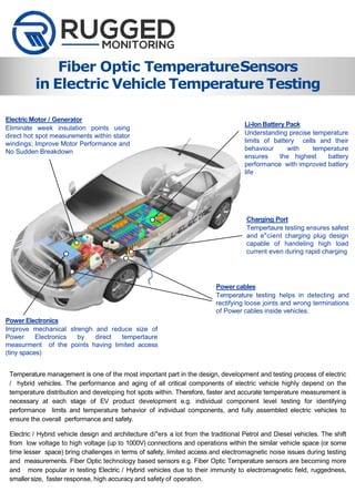
- 1. Fiber Optic TemperatureSensors in Electric Vehicle Temperature Testing Temperature management is one of the most important part in the design, development and testing process of electric / hybrid vehicles. The performance and aging of all critical components of electric vehicle highly depend on the temperature distribution and developing hot spots within. Therefore, faster and accurate temperature measurement is necessary at each stage of EV product development e.g. individual component level testing for identifying performance limits and temperature behavior of individual components, and fully assembled electric vehicles to ensure the overall performance and safety. Electric / Hybrid vehicle design and architecture di"ers a lot from the traditional Petrol and Diesel vehicles. The shift from low voltage to high voltage (up to 1000V) connections and operations within the similar vehicle space (or some time lesser space) bring challenges in terms of safety, limited access and electromagnetic noise issues during testing and measurements. Fiber Optic technology based sensors e.g. Fiber Optic Temperature sensors are becoming more and more popular in testing Electric / Hybrid vehicles due to their immunity to electromagnetic field, ruggedness, smallersize, faster response, high accuracy and safety of operation. Li-Ion Battery Pack Understanding precise temperature limits of battery cells and their behaviour with temperature ensures the highest battery performance with improved battery life Charging Port Tempertaure testing ensures safest and e"cient charging plug design capable of handeling high load current even during rapid charging Power cables Temperature testing helps in detecting and rectifying loose joints and wrong terminations of Power cables inside vehicles. Power Electronics Improve mechanical strengh and reduce size of Power Electronics by direct tempertaure measurment of the points having limited access (tiny spaces) Electric Motor / Generator Eliminate week insulation points using direct hot spot measurements within stator windings; Improve Motor Performance and No Sudden Breakdown
- 2. Power Train and Electric Motors Higher load variation in EV/HEV motors increases the risk of insulation failure under varying ambient conditions. Fiber optic temperature sensors are most suitable in testing motor insulation under extreme conditions in order to identify the performance limits and any week point within the insulation. • Due to their dielectric nature sensors can be fitted within windings to measure direct hot spot • Safe to operate and test; FO sensors are being used in transformer windings up to 1000kV • Easy to use (Plug ad Play) sensors; no expensive calibration needed • Accurate testing of cooling system efficiency during the complete vehicle testing • Use CANBUS to communicate with other test systems / dataloggers 02 Benefits of Fiber Optic Temperature Sensors Battery Bank andCells EV/HEV batteries generate excessive heat during rapid charging and discharging resulting into the sudden increase of cell temperature. A small short circuit in the cells could result into sever accident under high ambient temperature and rapid charging due to the thermal runaway of Li-Ion. Fiber Optic (FO) temperature sensors bring lot of benefits during the intensive temperature testing of battery bank and cells. • Higher immunity to electromagnetic interferences increases the testing accuracy and repeatability • Faster response time of 0.1second to 1ms helps in identifying sudden temperature increase within cells • Rugged sensor tip (vibration withstand capability of 8g) is suitable for all test conditions • Sensors and monitors are easy to reuse as they do not require recalibration or complex inputs to operate • The CANBUS is implemented to communication with dataloggers or car Battery Management System.
- 3. Charging ports heat up quickly during the rapid charging and with consistent charging power. An inefficient charging port design results into customers su"ering with lengthy charging process. Fiber Optic (FO) temperature sensors are safest, accurate and reliable for conditions like charging port testing. • Direct installation at the charging port increases the accuracy testing • Sensors are safe to operate and test under high voltage conditions • Sensors and monitors are easy to reuse as they do not require recalibration or complex inputs to operate • Use CANBUS to communicate with other test systems / dataloggers Power Electronics Testing Power electronics for temperature consistency and vibration is very critical to ensure their continuous operation throughout the vehicle life. Fiber optic temperature sensors fitted into limited space available in this area provide the same response and accuracy. • The small sensors (up to 0.4mm diameter) that can fit into tiniest space into power electronics • Easy to reuse (Plug ad Play) sensors with dielectric replaceable tip; no expensive calibration needed • Accurate testing of cooling system efficiency during the complete vehicle testing • Use CANBUS to communicate with other test systems / dataloggers ChargingPort HV Cables and Large Current Terminals HV cables and large current terminals are subject to loose connections and joints resulting into intermittent partial discharge and developing hot spots. Fiber Optic temperature sensor are being used at HV cable joints and terminations during the overall testing of EV/HEV. • Direct installation at the joints and large current terminals to get maximum accuracy • Sensors are safe to operate and test for short- circuit testing applications • The small sensors (up to 0.4mm diameter) that can fit into tiniest space at joints and terminals • Easy to reuse (Plug ad Play) sensors with dielectric replaceable tip; no expensive calibration neededs • Use CANBUS to communicate with other test systems / dataloggers 03
- 4. 04 Our Solution: SystemArchitecture We provide range of fiber optic temperature sensors, monitors and accessories to component as well as EV/HEV manufacturers. Fiber optic sensors and monitors are being used during the product testing of electric motors, batteries, power trains, power electronics, and charging ports. Similar sensors and monitors are also being used during the complete vehicle testing at car manufacturing plants or test laboratories. Our solution supports both distributed and centralized architecture as shown in below figure. Centralized architecture is mostly used by component manufacturers and distributed architecture is ideal for complete vehicle testing. FO sensor and modules are designed for harsh automotive test conditions and to fit into small spaces available into the test vehicles. R501 FO Module R501 FO Module R501 FO Module R501 FO Module R501 FO Module HighSpeed CANBUS HighSpeed CANBUS HighSpeed CANBUS High Speed CANBUS ConfigurableIO Modules (Analog/Digital) Rugged Connect software for configuration and visualization PC/Laptop Configurable Relay Output High Speed CANBUS
- 5. 05 System Configuration Equipment (System Component) Quantity with Comments BATTERY BANK FO Temperature Sensors 01(for each Battery Cell) FO Temperature Monitor 01to 08 Multi-Channel Units (R501)with CANBUSsupport AC MOTOR FO Temperature Sensors 20 to 60 (depending on the design of the ACMotor) FO Temperature Monitor 01Multi-Channel Unit (R501)with CANBUSsupport TRANSMISSION FO Temperature Sensors 02 FO Temperature Monitor 02 Channel OEM Module (O201)with CANBUS support CHARGING PORT FO Temperature Sensors 01(for each Charging Port) FO Temperature Monitor 02 Channel OEM Module (O201)with CANBUS support POWER ELECTRONIC S FO Temperature Sensors 04 to 08 (depending on the design) FO Temperature Monitor 08 Channel OEM Module (O201)with CANBUS support CABLES & TERMINAL S FO Temperature Sensors 01(for each Joint and Termination) FO Temperature Monitor 08 Channel OEM Module (O201)with CANBUS support COMPLET E EV/HEV FO Temperature Sensors app. 50 to 125 fiber optic sensors FO Temperature Monitor 05 to 16OEM Modules (O201, 08-Channel) with CANBUS support Computer R5O1 Tsens
- 6. 06 Fiber Optic Temperature Sensor (LSENSB) Specifications • Measurement range: -80⁰C (-112⁰F)to +250⁰C (+482⁰F) • Response time: 35ms; 1msavailable as a sepa rate option • Accuracy: ±0.2⁰C (relative temperature) • Repeatability: 0.2⁰C • Available at any length • With industry standard ST connector Features • Small diameter (04.mm) for fast response and fitting into places with very limited space • Outstanding repeatability improves accuracy of testing instruments • Rugged sensor suitable for HV applications • Plug and Play operation, does not require setup or calibration • Minimal thermal shunting Accessories The following standard accessories for fiber optic temperature sensors are provided in order to fit to customer needs and installation requirements: Fiber Optic extension cables for applications where test equipment are very far from test object Terminal rings for fiber optic probe tip mounting for places like cable terminals, battery etc. Fiber Optic Temperature Sensor TSENS) Specifications • Measurement range: -80⁰C (-112⁰F)to +250⁰C (+482⁰F) •Response time: 200ms; 1msavailable as a sepa rate option • Accuracy: ±0.2⁰C (relative temperature) • Repeatability: 0.2⁰C • Available in any lengths, up to 25 meters • With industry standard ST connector Features • Rugged sensor suitable for HV applications • Meets the harsh testing conditions of electric motors and transmission system • Very high resistance to pulling (>60N) • Solvent and chemical resistant • Highly stable sensor, does not require any calibration Fiber Optic Cable connectors (Metal and Dielectric) to connect two Fiber Optic and Extension cables Disposable Dielectric Tip that allows Fiber Optic sensors to be reused 400um
- 7. 07 Fiber Optic Temperature Monitor (R501) Specifications •Input Power requirement: 24Vdc, Optional USB powered •Expandable to 256 Channels, Daisy chain up to 32 units (with Modbus, Canbus) • Resolution: 0.1⁰C • Measurement Range: Measurement range: -80⁰C (-112⁰F)to +250⁰C (+482⁰F) •Operating Temperature: -40°C(-40°F)to +72°C (+162°F) • Operating Humidity: 95% Non Condensing • Protocol: CANBUS, Modbus, DNP3.0, IEC61850 Features •Fully flexible rack mount and distributed architecture support •Scalable and field upgradable from 02 to 256 channels with plug and play modules • Best in class EMI,ESDImmunity • Rugged design to suit harsh testing conditions of automotive industry •Expandable to add di"erent analog and (or) digital inputs and outputs •Range of communication options for third party system integration •High speed CANBUS implemented to suit automotive industry applications Fiber Optic Temperature Monitor (O201) Specifications •Input Power requirement: 24Vdc, Optional USB powered • Number of Channels: 01to 08 • Resolution: 0.1⁰C • Measurement Range: Measurement range: -80⁰C (-112⁰F) to +250⁰C (+482⁰F) •Operating Temperature: -40°C(-40°F)to +72°C (+162°F)with 95% Humidity • Dimensions: 125mm x 125mm x 48mm • Protocol: CANBUS, Modbus, DNP3.0, IEC61850 Features • Rugged compact design for automotive industry • Plug and Play installation and operation • Best in class EMI,ESDImmunity • Multiple mounting options: Independent, Dinrail, and direct (without enclosure) • Analog and Relay outputs with custom logic feature (Customer configurable) • Range of communication options for third party system integration • High speed CANBUS implemented to suit automotive industry applications Fiber Optic Temperature Monitor (L201) Specifications •Input Power requirement: 24Vdc, Optional USB powered • Number of Channels: 02 to 08 (expandable) • Resolution: 0.1⁰C • Measurement Range: Measurement range: -80⁰C (-112⁰F) to +250⁰C (+482⁰F) •Operating Temperature: -40°C(-40°F)to +72°C (+162°F)with 95% Humidity • Dimensions: 125mm x 18mm x 69 mm • Protocol: CANBUS, Modbus, DNP3.0, IEC61850 Features • Rugged compact design for automotive OEM • Handheld unit for quick testing (Plug and Play) • Best in class EMI,ESDImmunity • No shift over time, high stability and repeatability • Range of communication options for third party system integration • High speed CANBUS implemented to suit automotive industry applications
- 8. 08 WHY RUGGEDMONITORING We are an industry leading team of fiber optic experts with 100+ years of combined experience, and are committed to deliver customizable solutions for challenging applications. Our team of experts leads through product innovation to deliver best in class reliability. We deliver reliable, high performance, precision sensors and monitoring solutions. Our mission is to: • Customer Service At Rugged Monitoring customers come first. Deliver best in class customer service, be first in mind and choice for customers. • Rugged Design Deliver Rugged, intrinsically safe sensors / solutions for the toughest applications. • Innovation Leading next generation product innovations with patented technologies. • Fiber Optic Experts Our team has extensive knowledge of Power Transformer Industry and viewed as leaders in fiber optic sensing technology. • Quality Focus Provide peace of mind to our customers by delivering quality products consistently. +1-418-767-0111 info@ruggedmonitoring.co m www.ruggedmonitoring.com S0011_Electric Vehicle_EN_A4_R01 2018 Rugged Monitoring Company. All rights reserved. Information subject to change without notice. All trademarks are properties of their respective companies, as noted herein. Rugged MonitoringServices Rugged Monitoring provides customization of sensors, monitors & software. In addition we o"er on-site commissioning services, maintenance contracts and technical support to all customers worldwide. About RuggedMonitoring Industry leading team of fiber optic experts with 100+ years of combined experience committed to delivering customizable solutions for challenging applications. We o"er a range of reliable, high performance, customizable sensors and monitoring solutions that are immune to external influence. Monitoring Software (RuggedConnect) Features • Web client based real time data visualization • Historic trending for user selectable duration • Easily customizable dashboards to meet di"erent application requirements • Monitoring of Signal strength for Fiber Optic signals for easy troubleshooting • Flexibility to Enable / Disable Channels remotely • Support for multiple languages • Drivers available for LabView, MATLABand python computing environments • CANBUS / MODBUS data output for high resolution data logging such as CAN Dataloggers