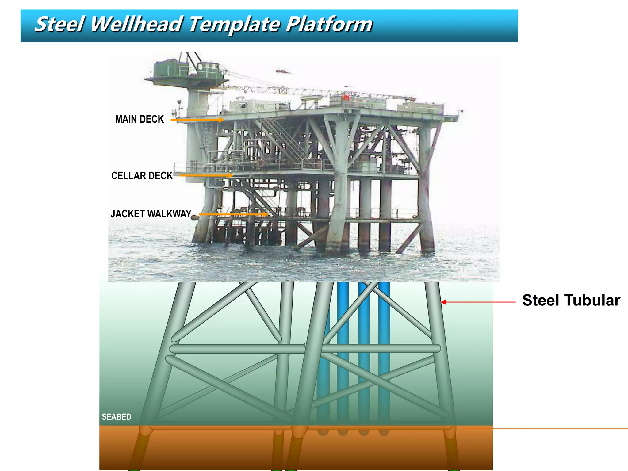
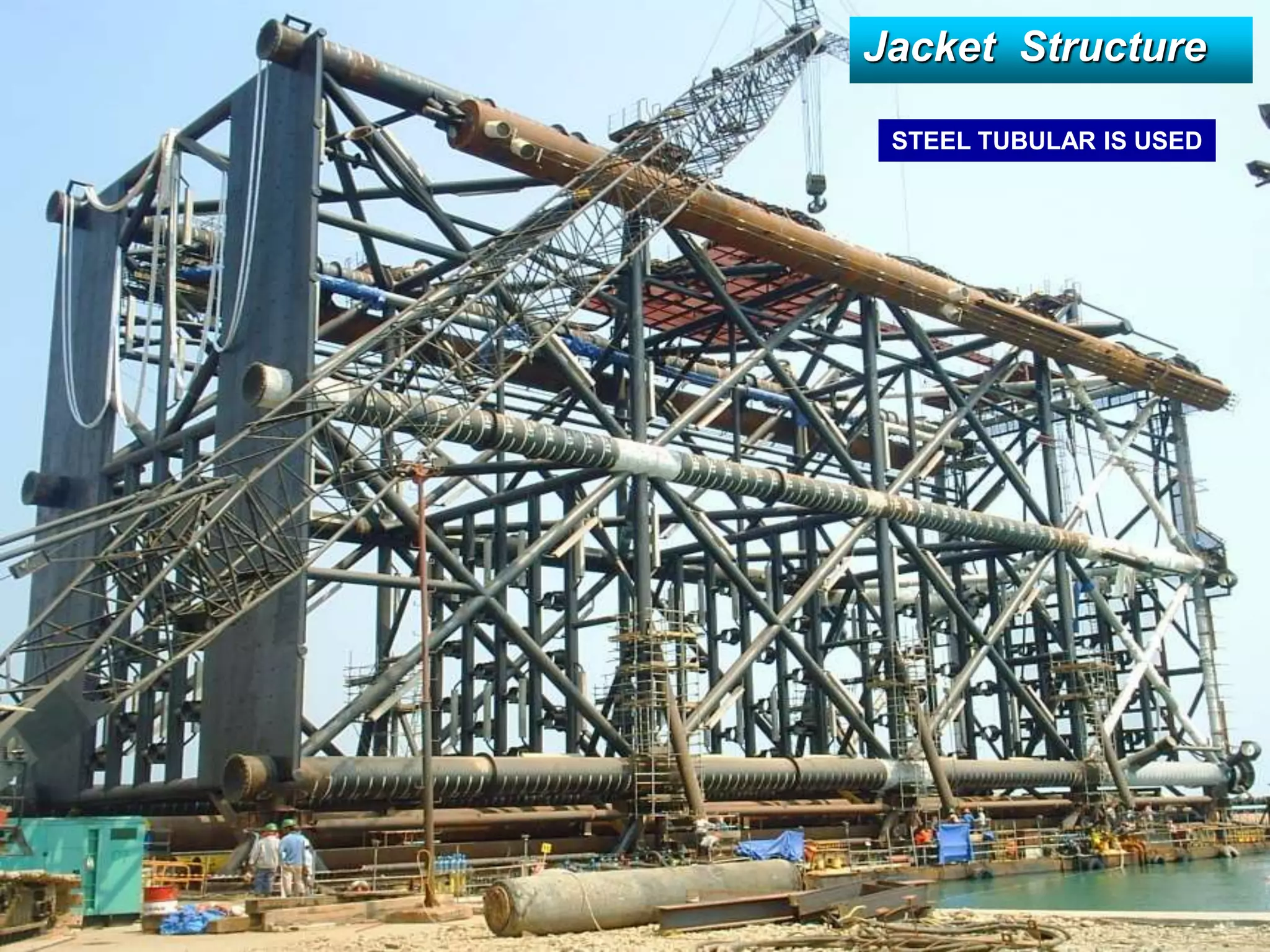
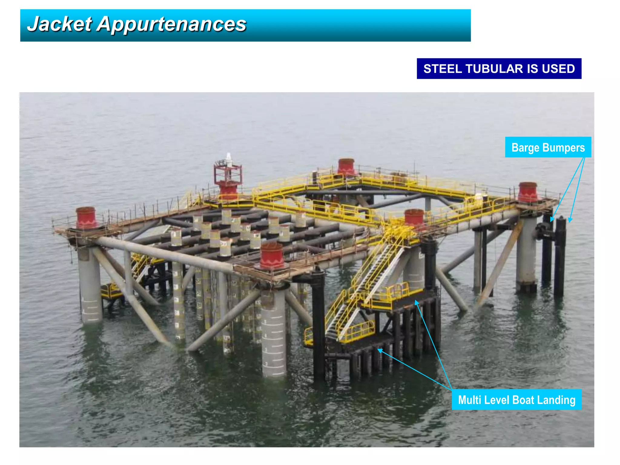
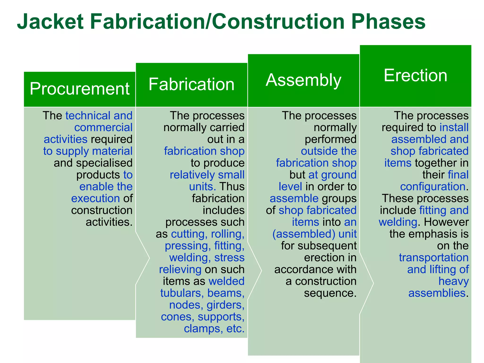
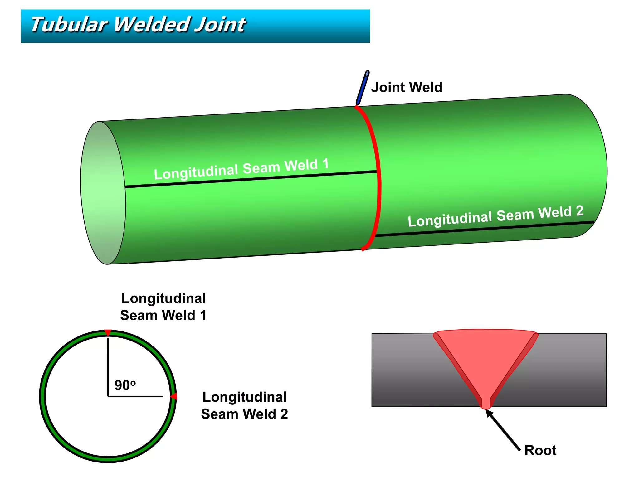
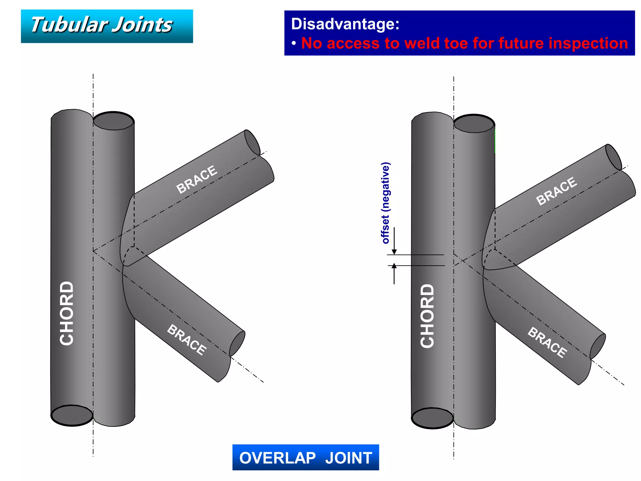
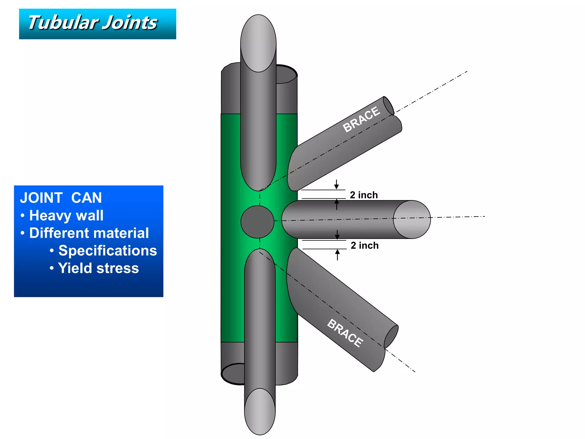
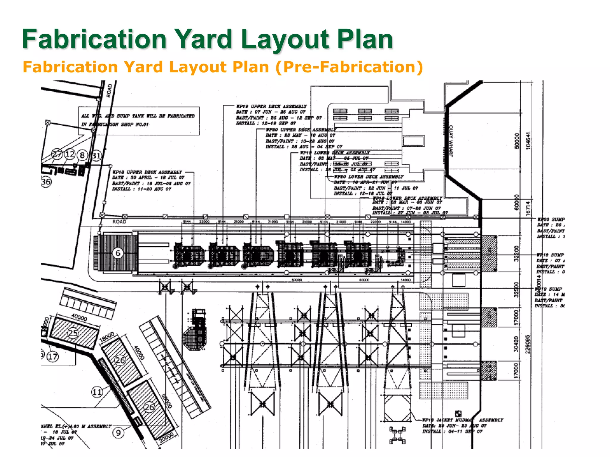
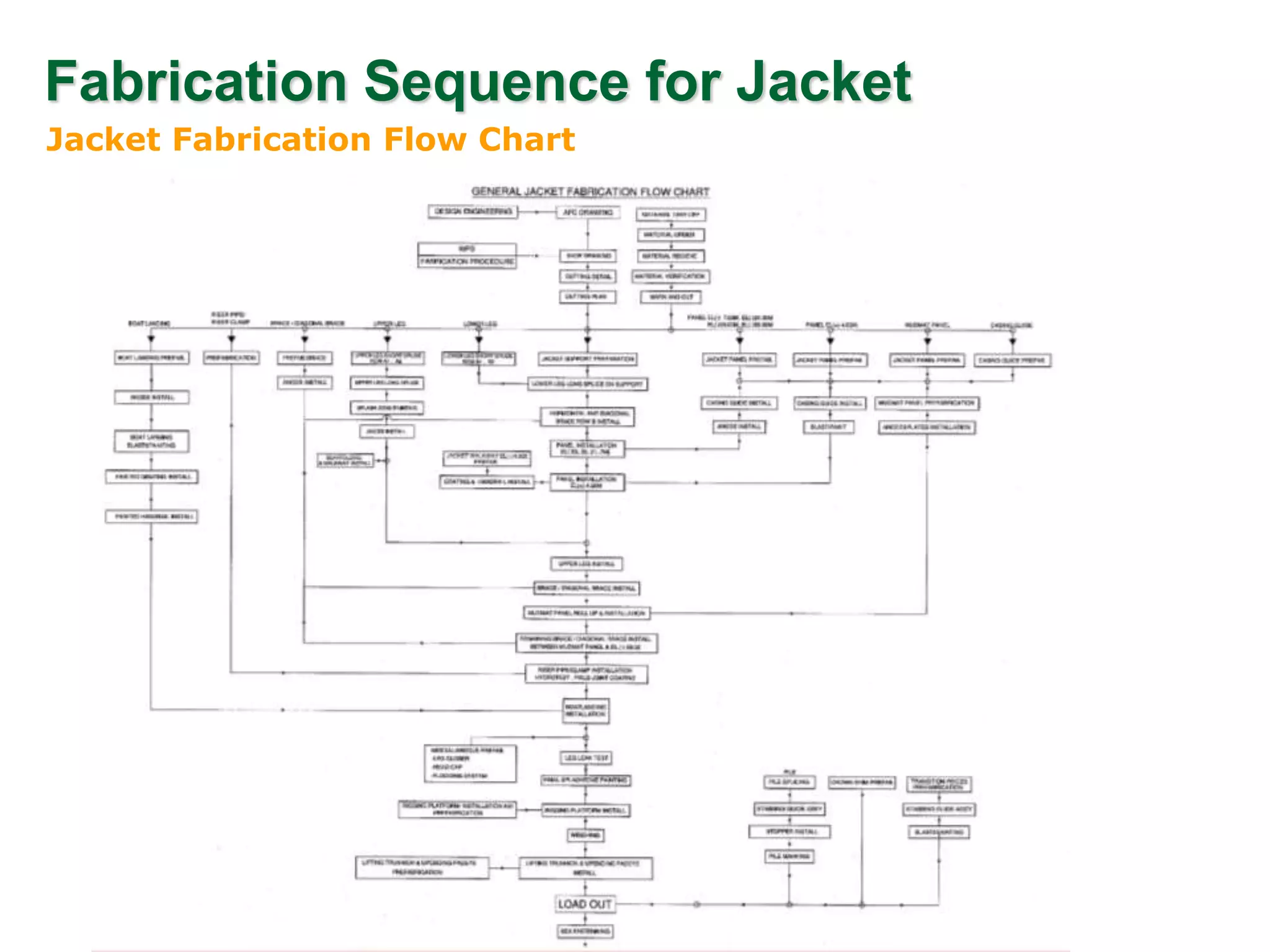
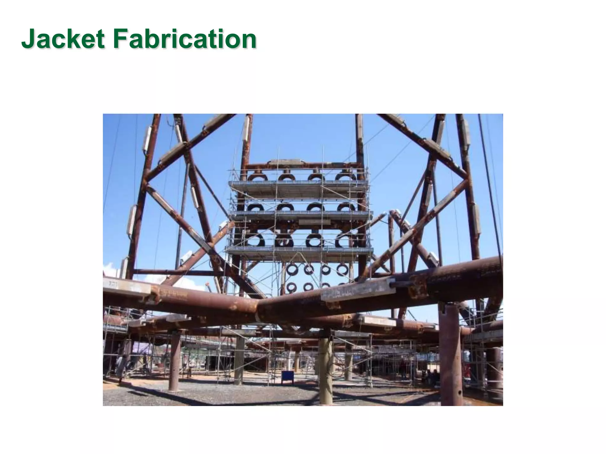
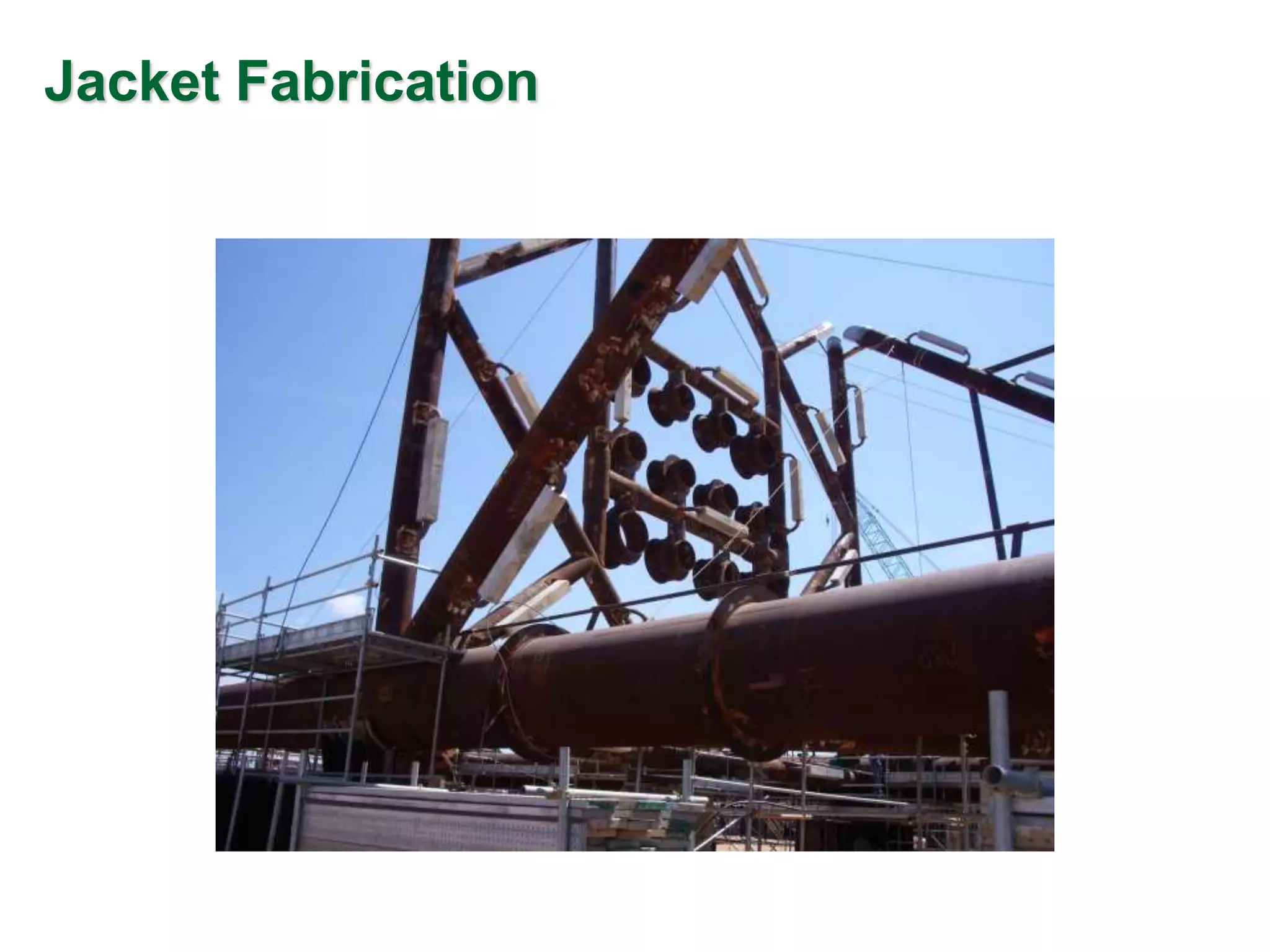
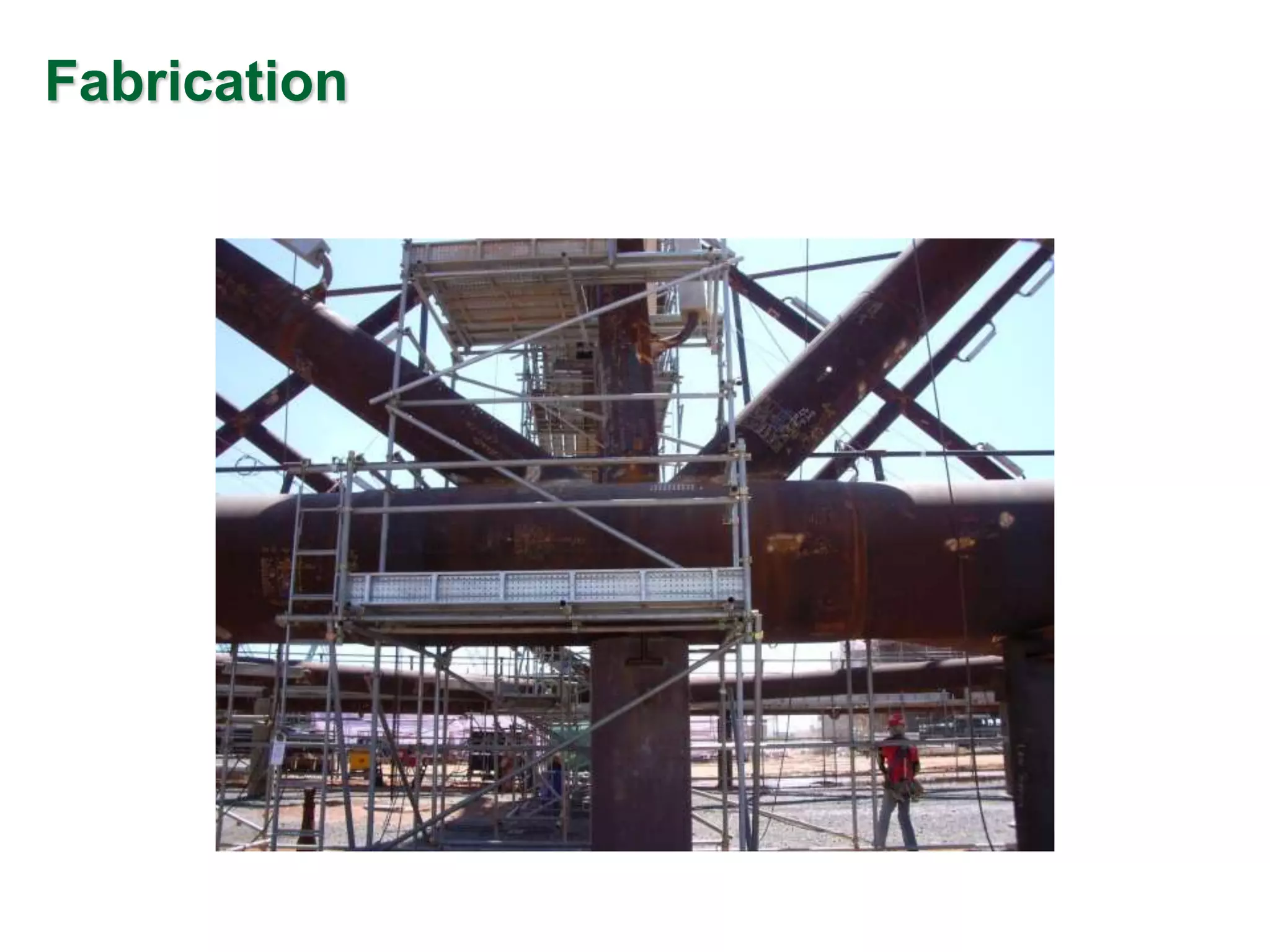
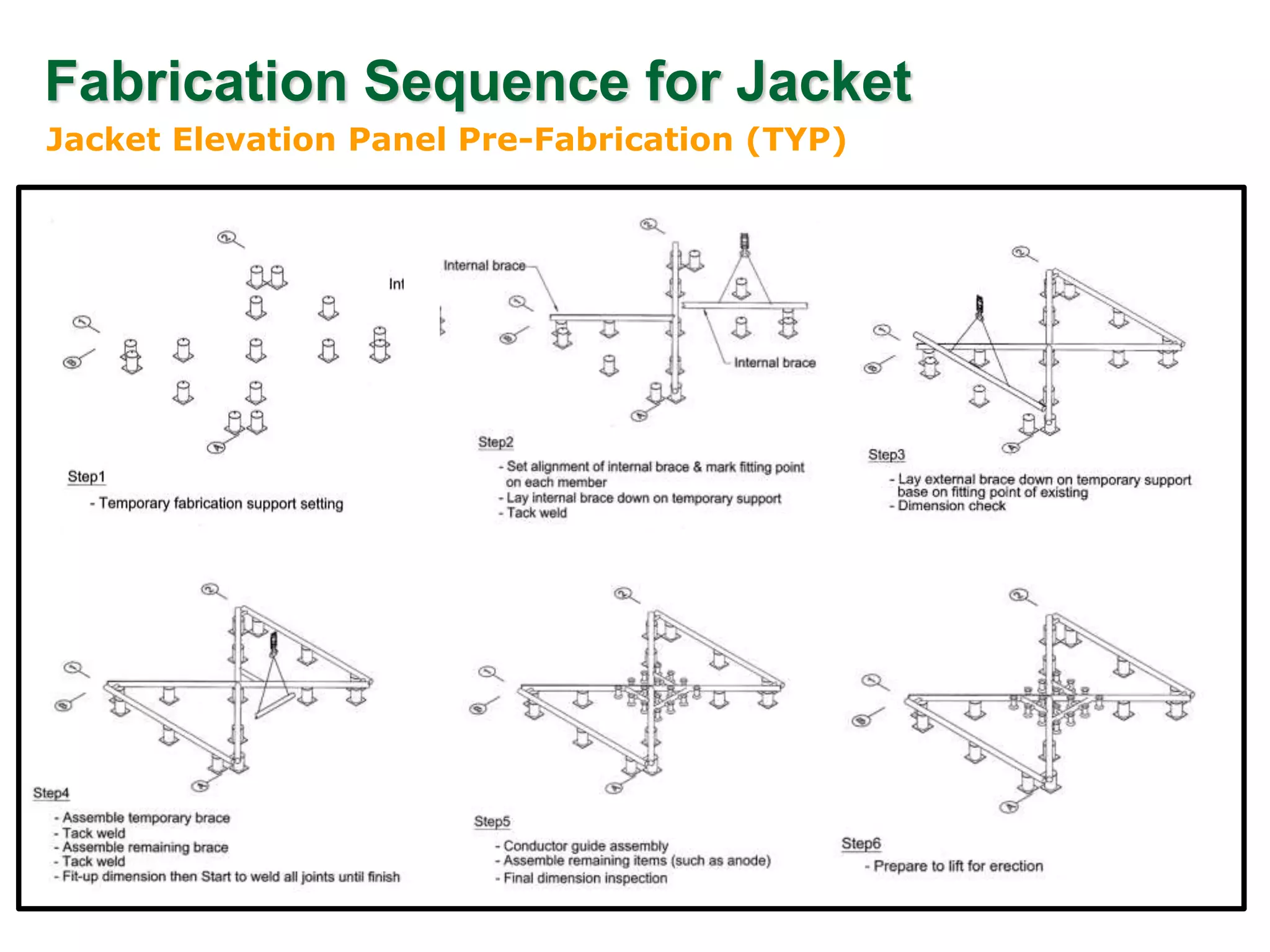
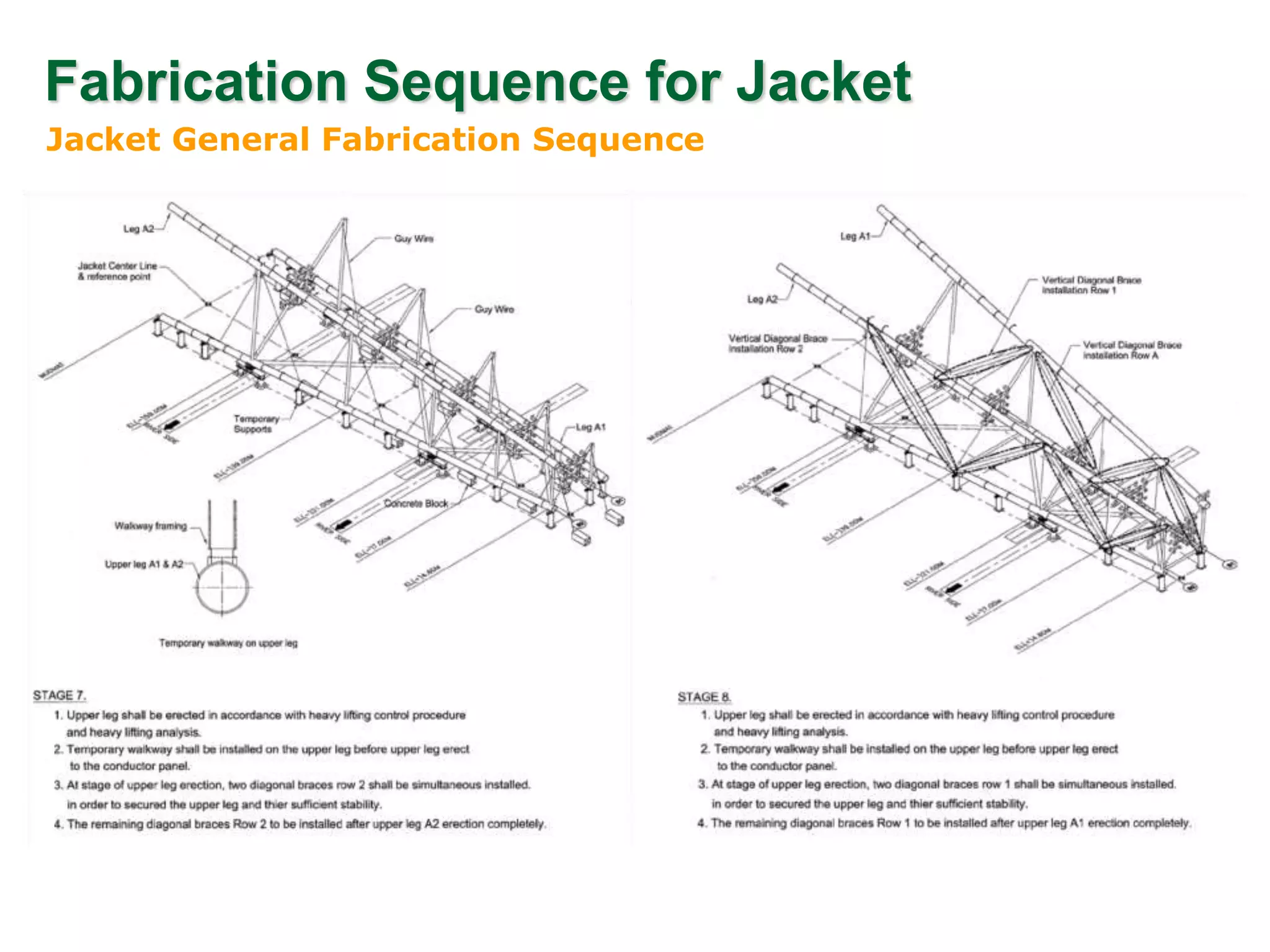
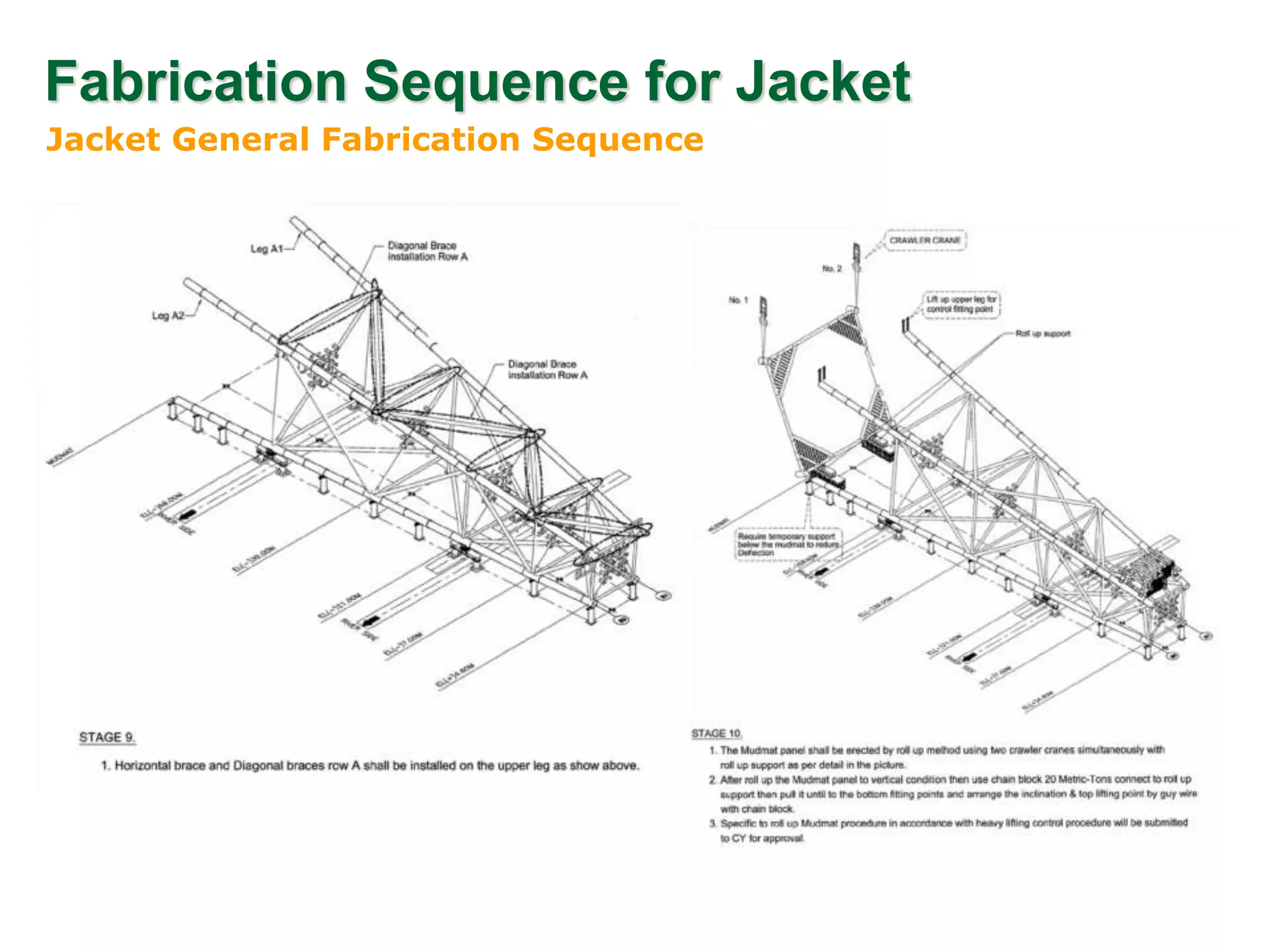
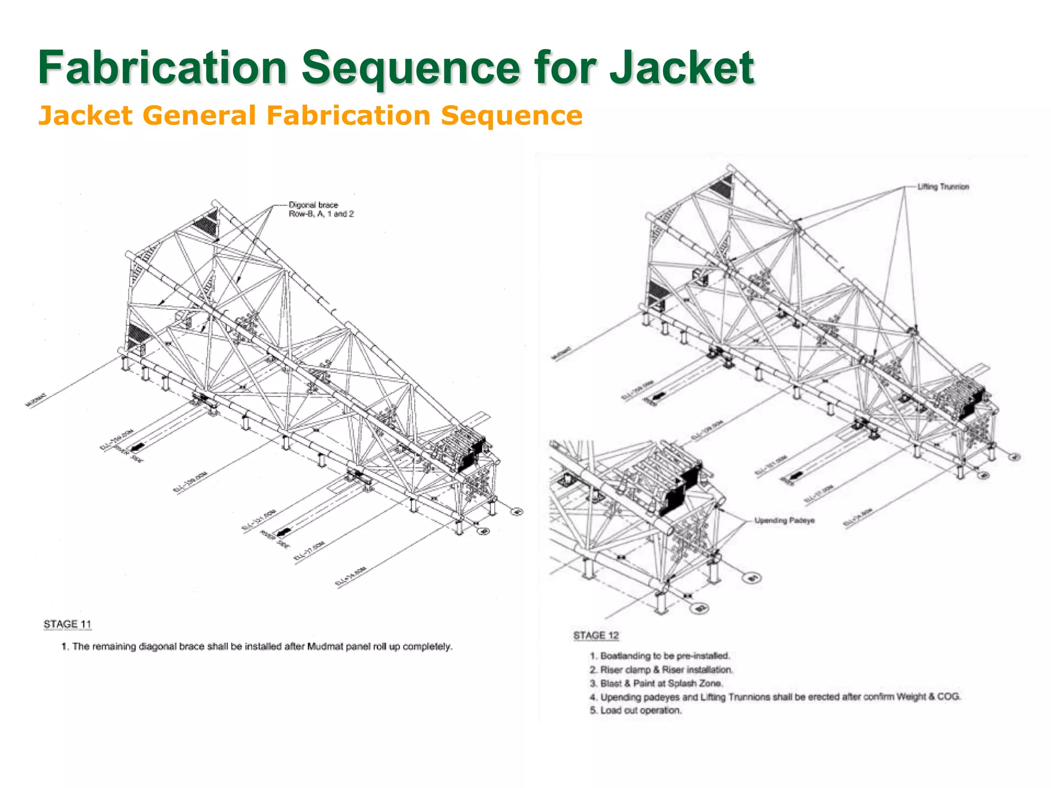
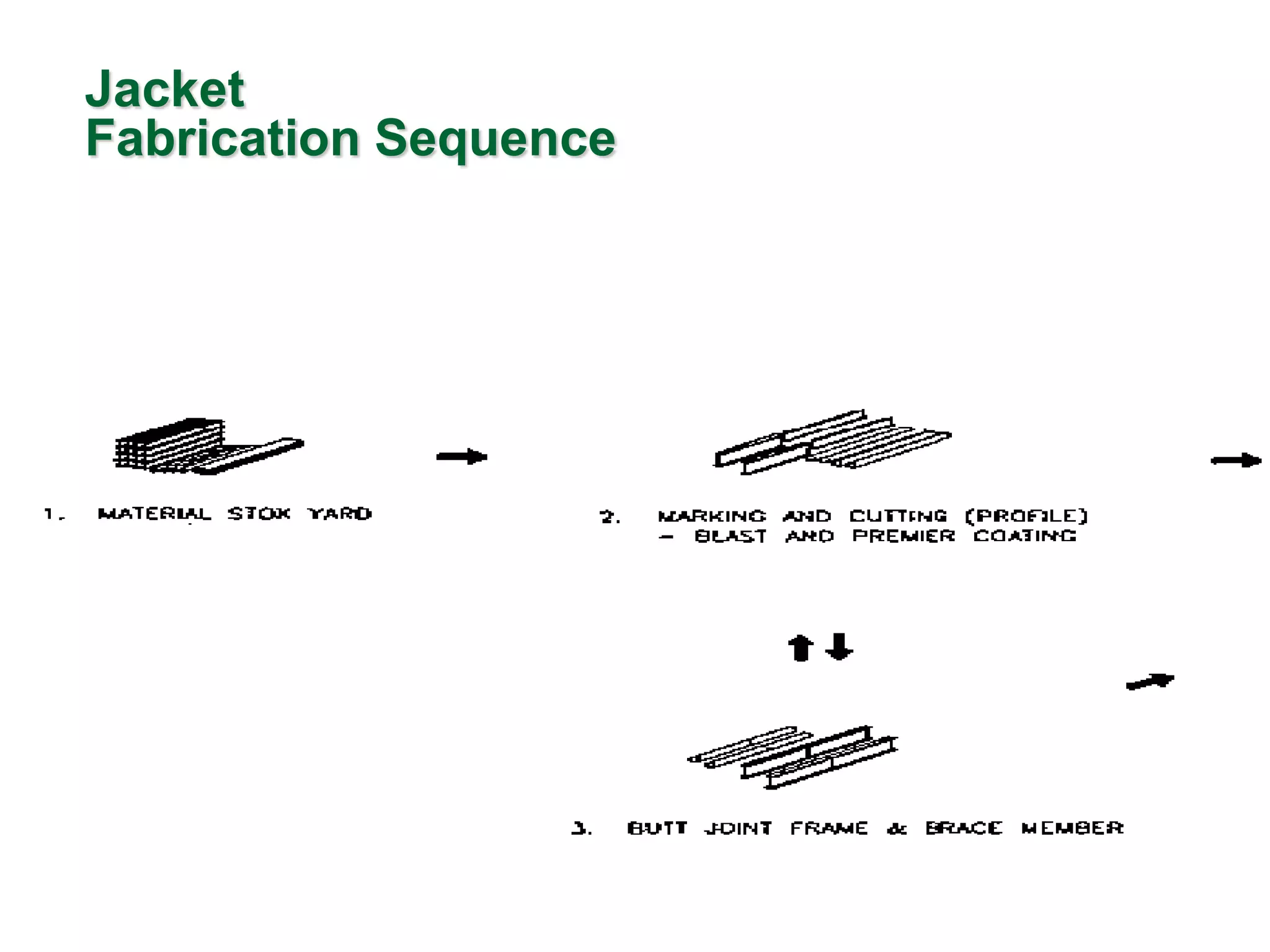
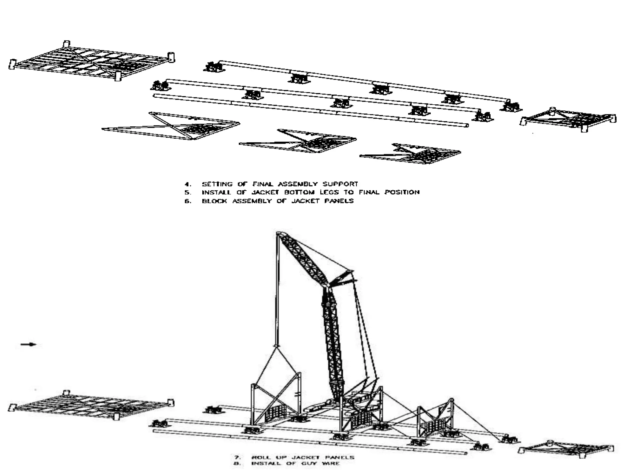
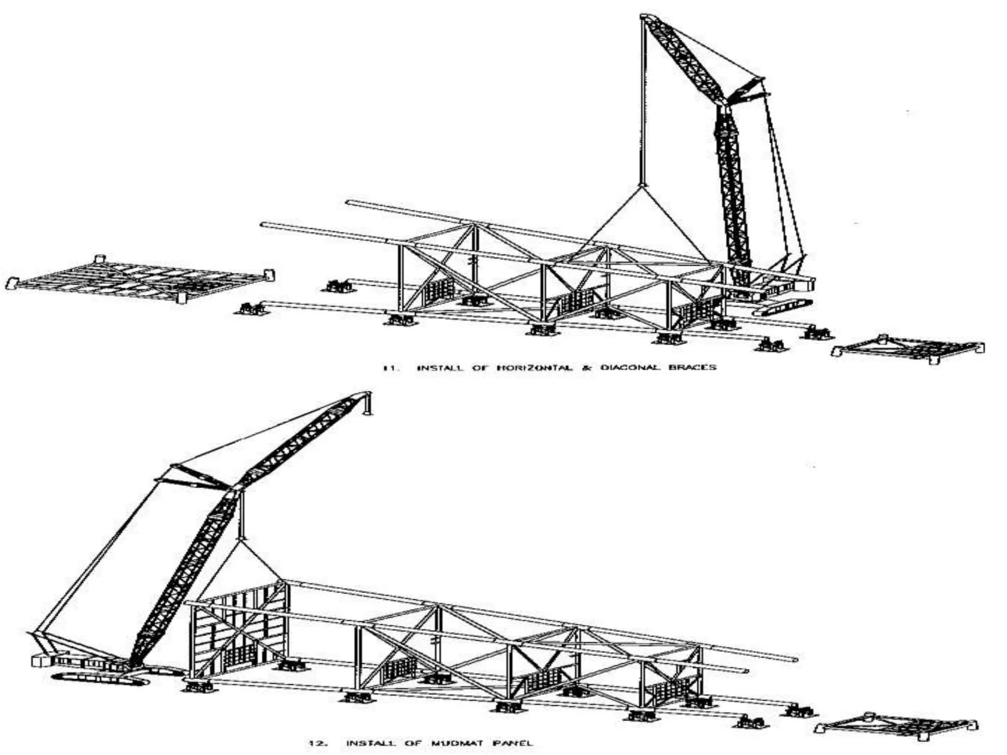
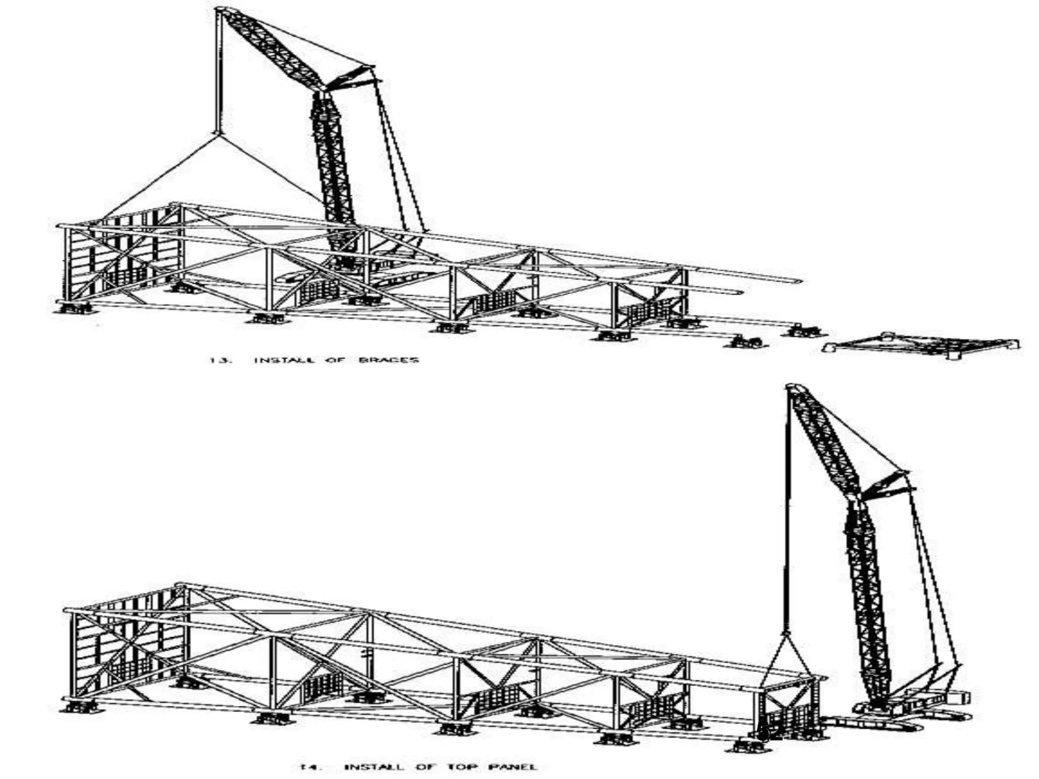
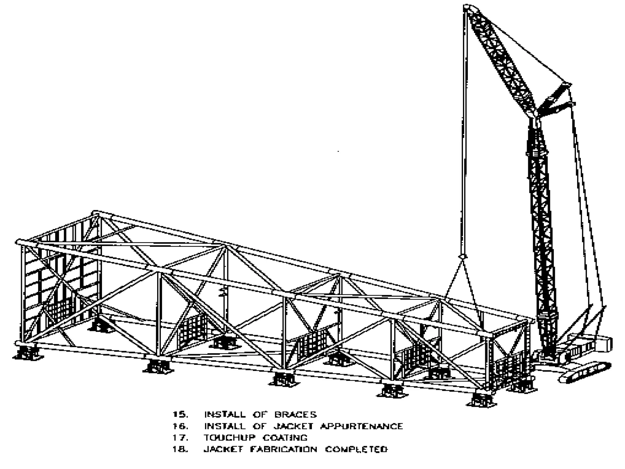
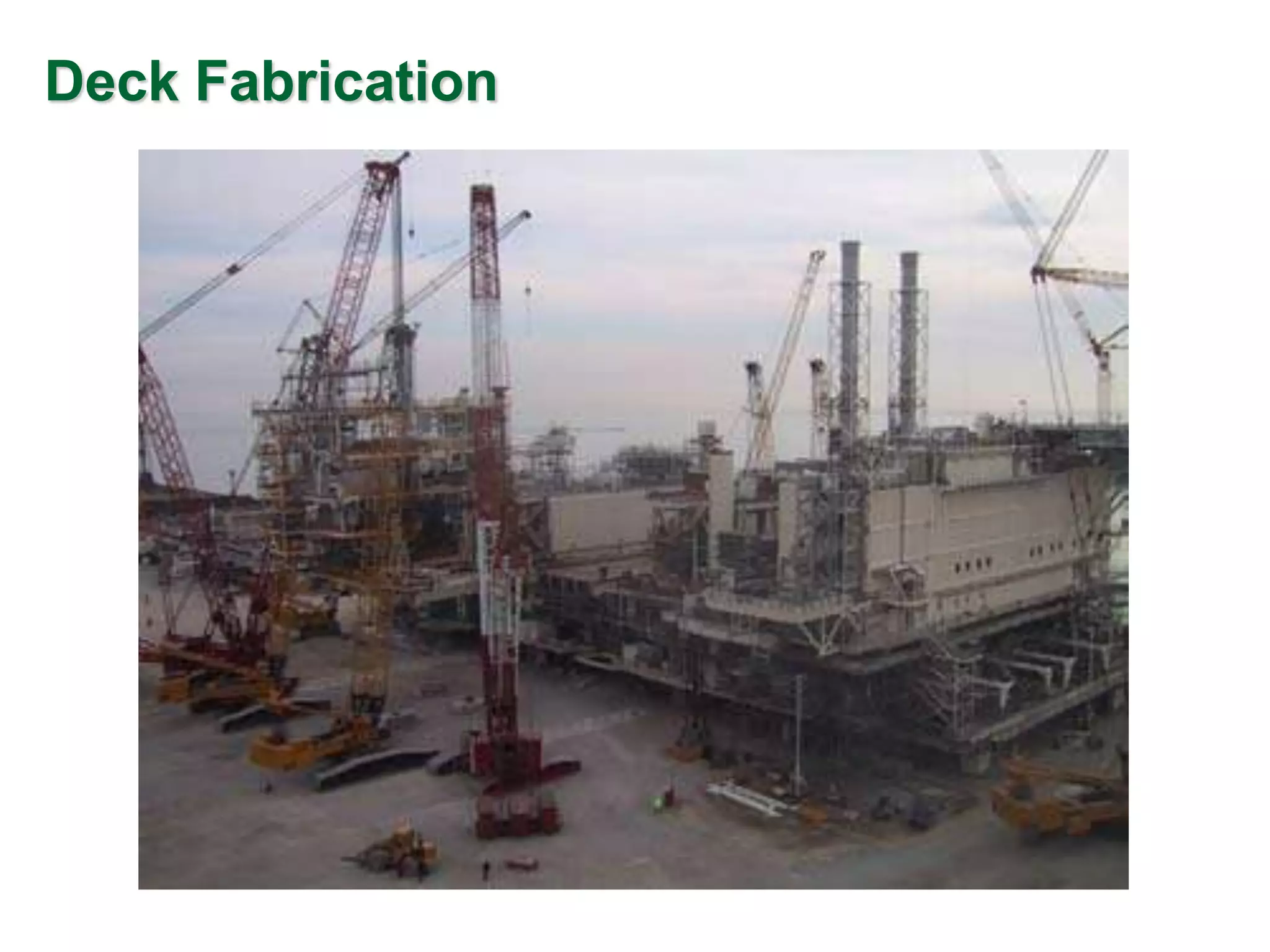
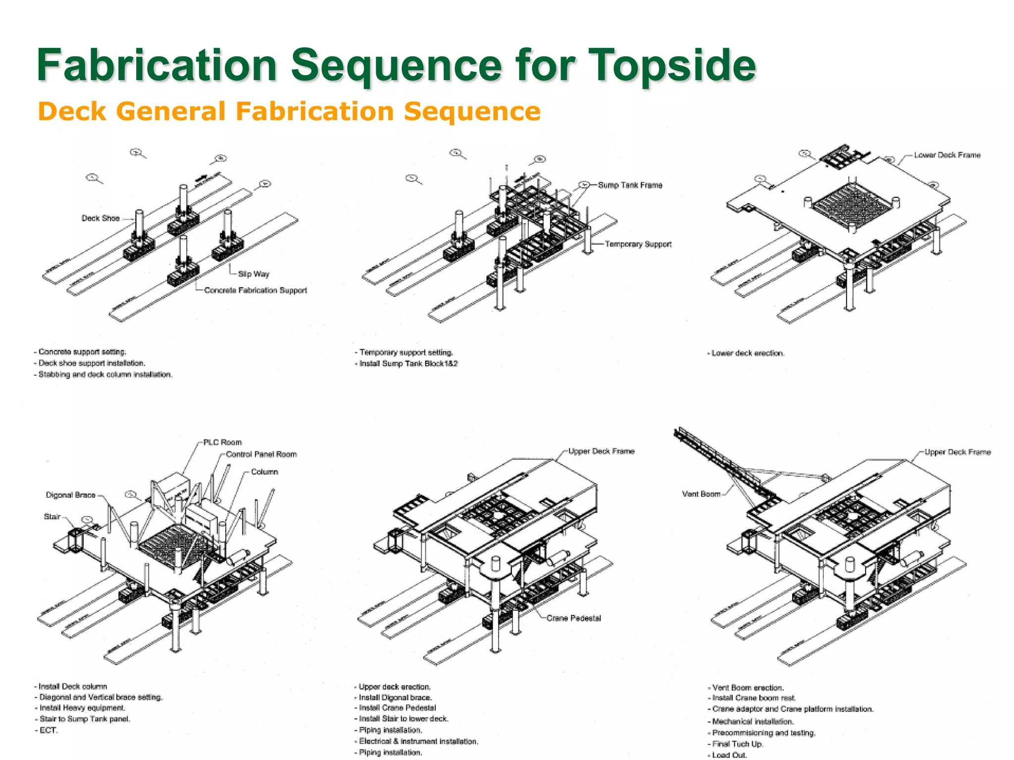
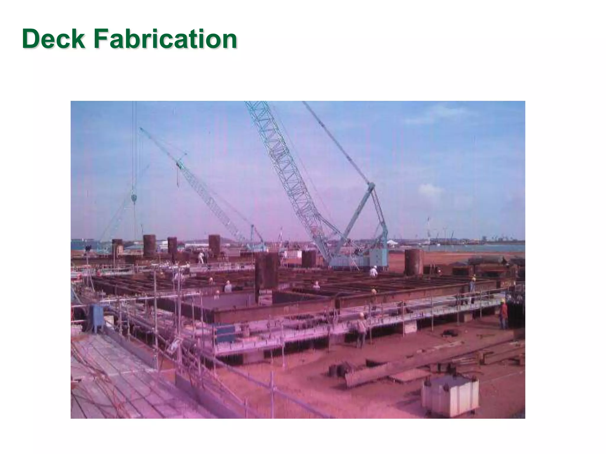
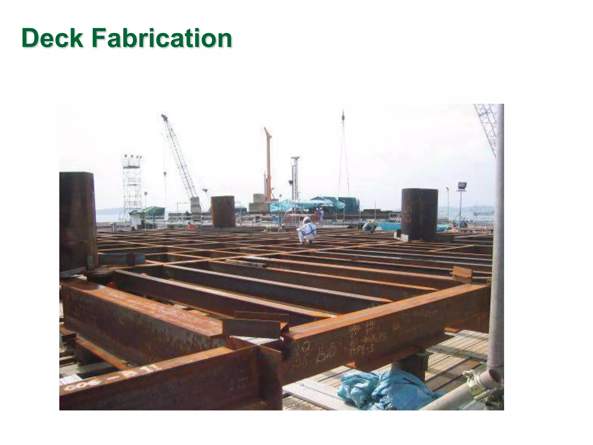
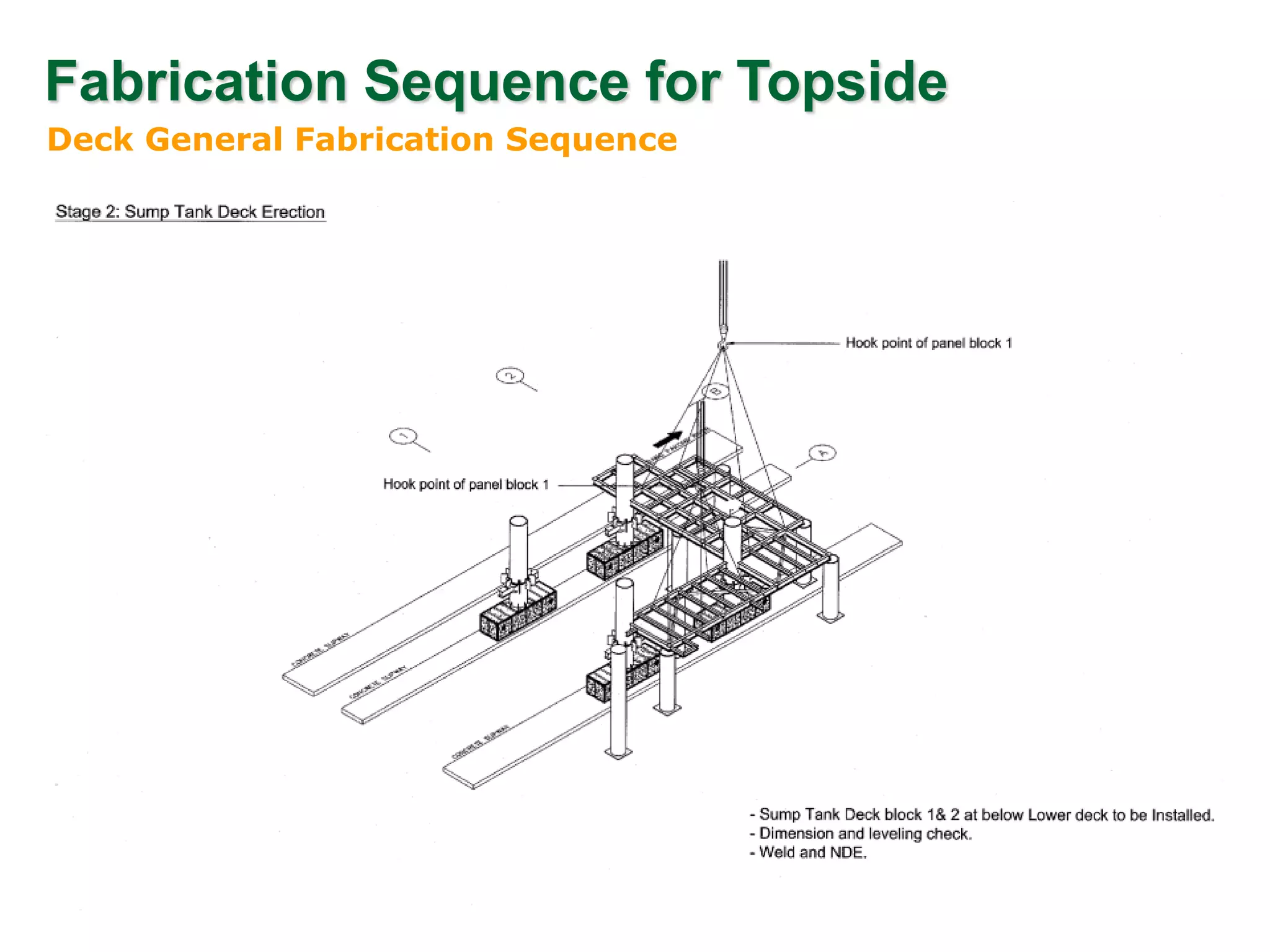
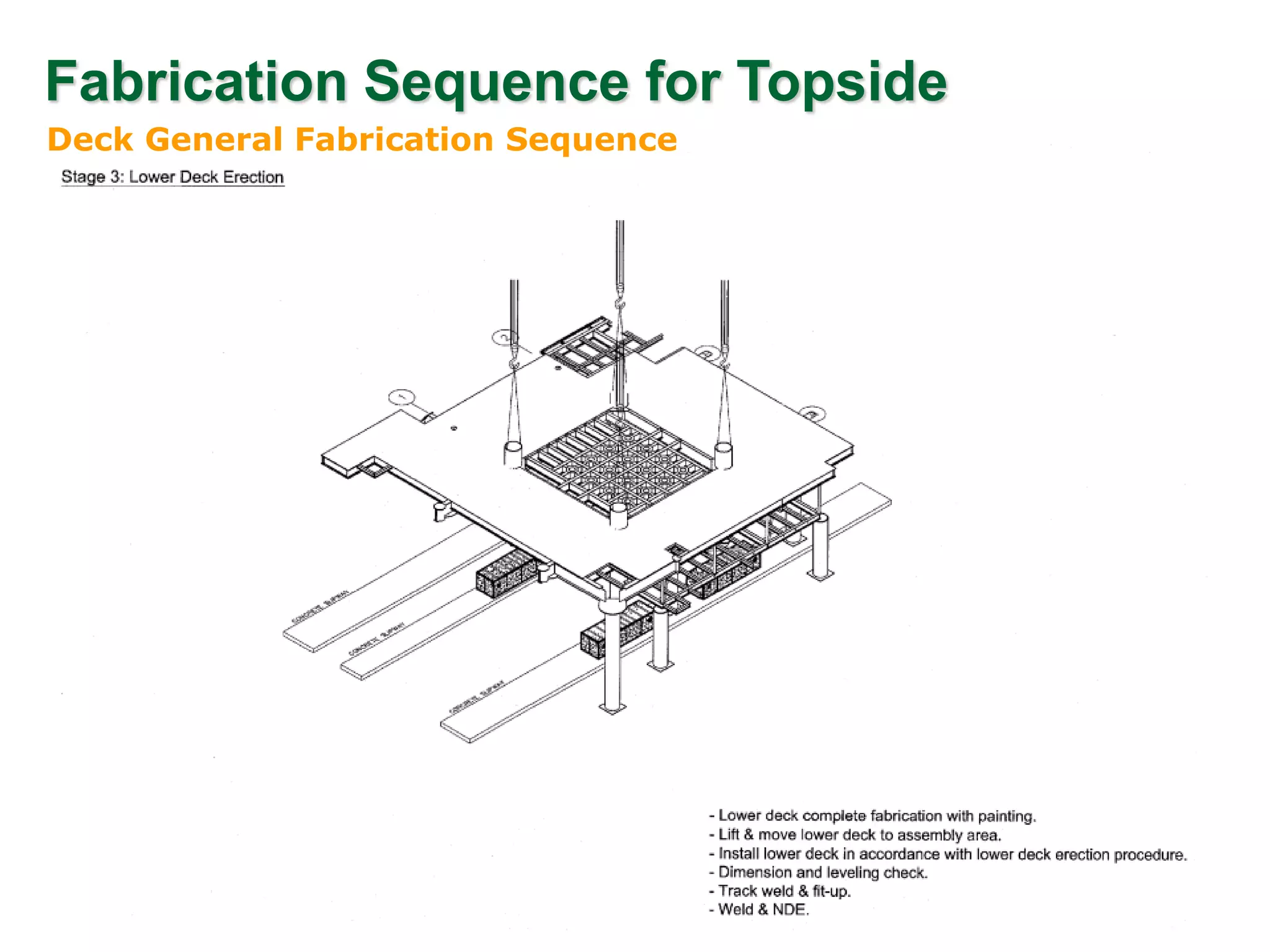
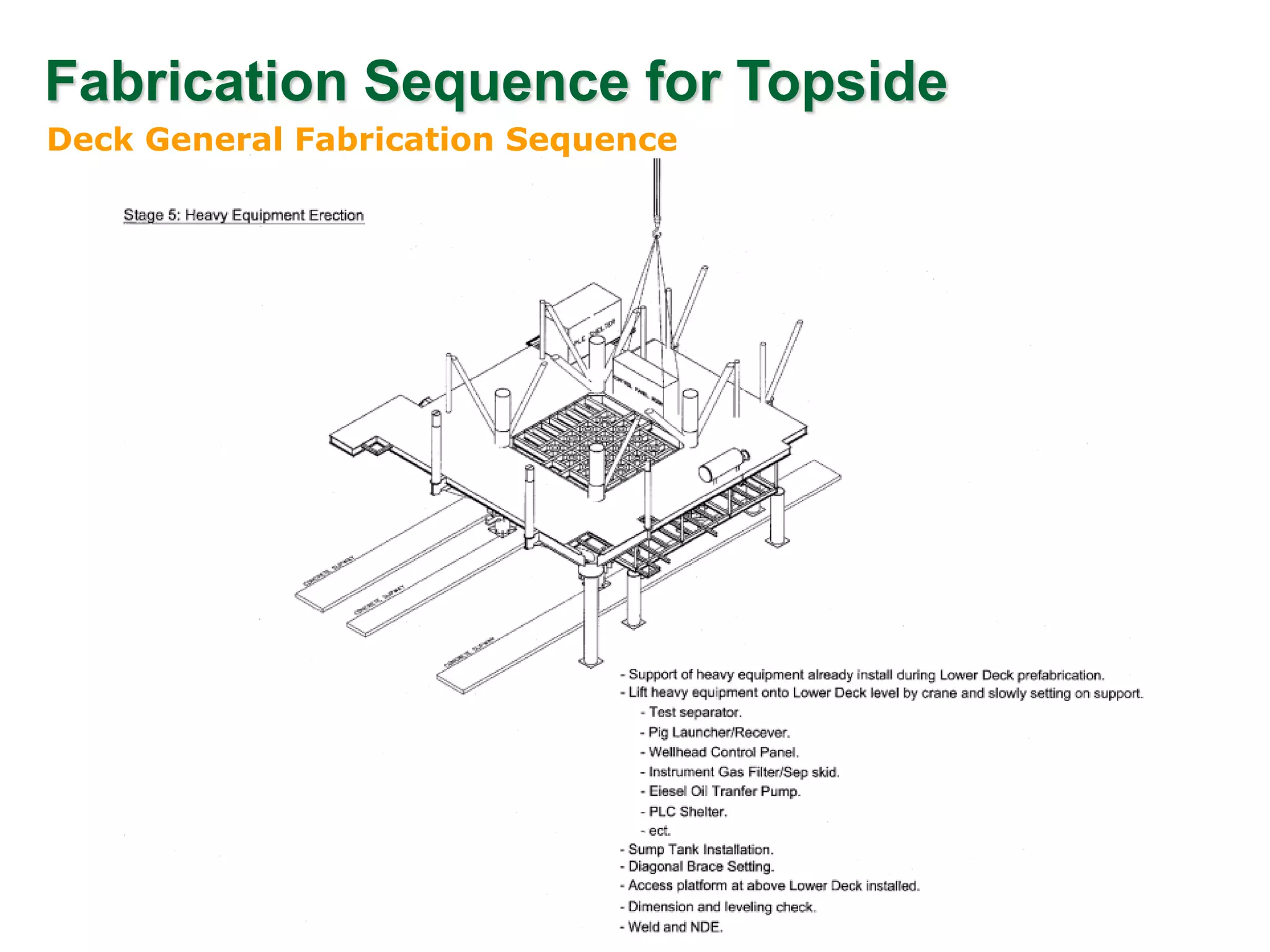
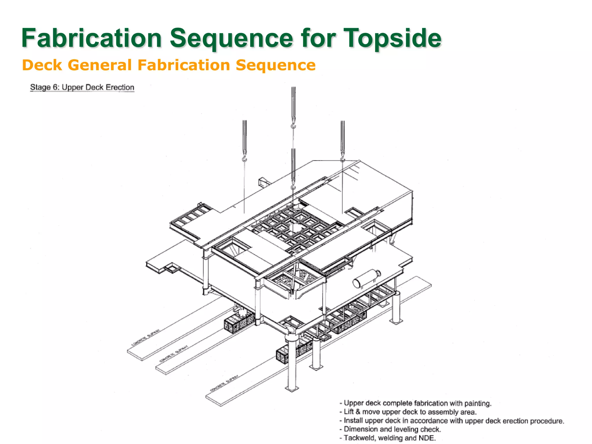
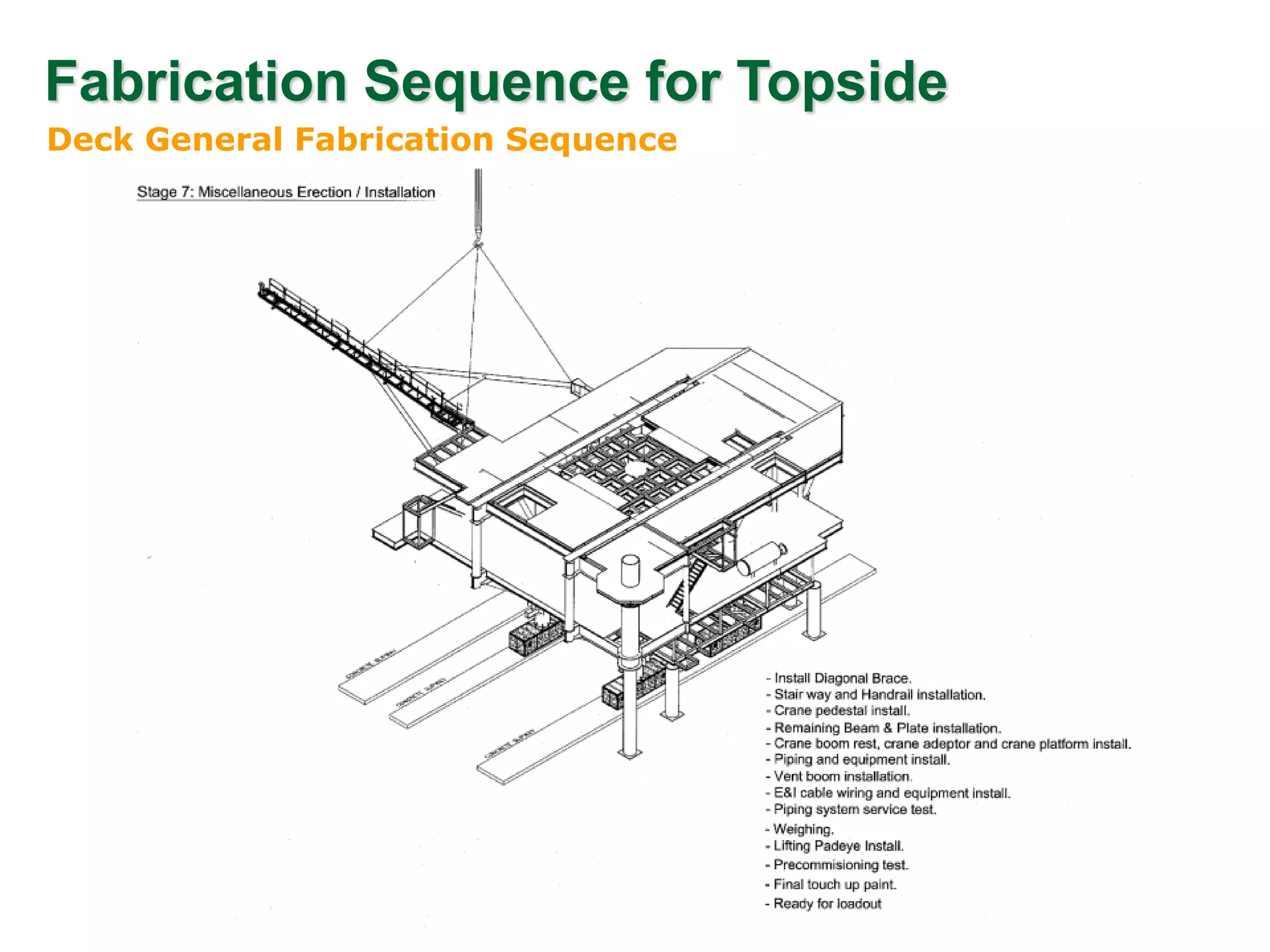
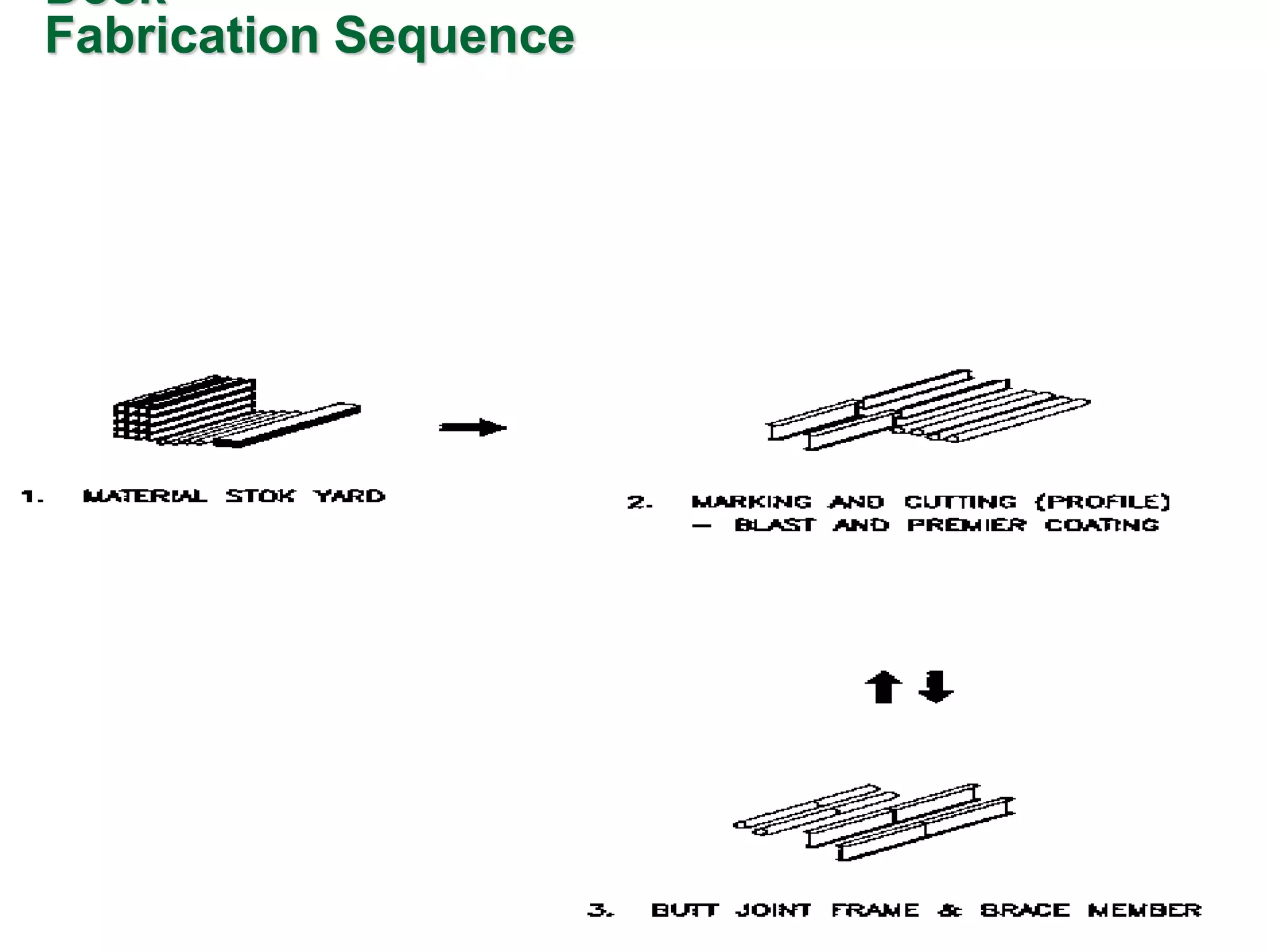
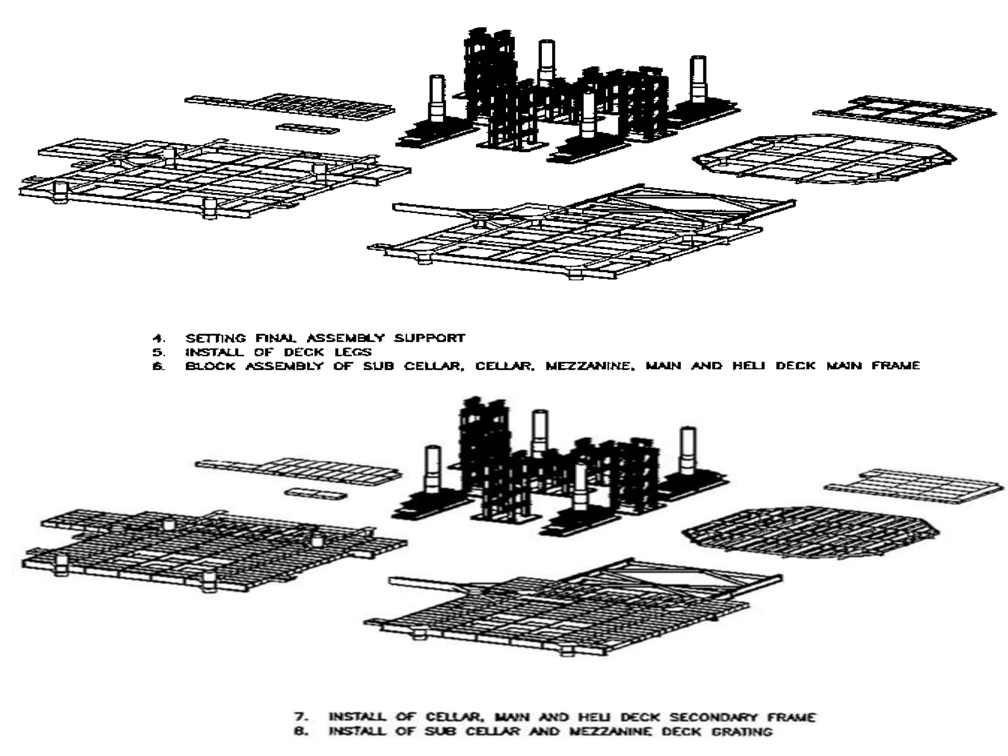
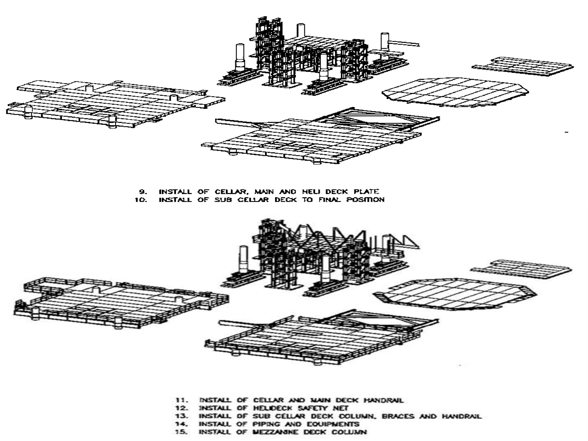
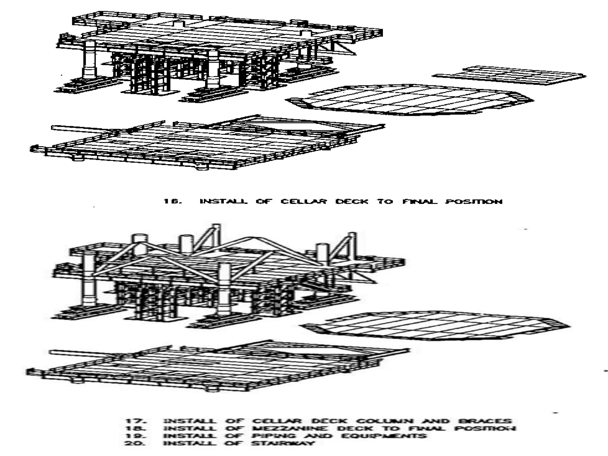
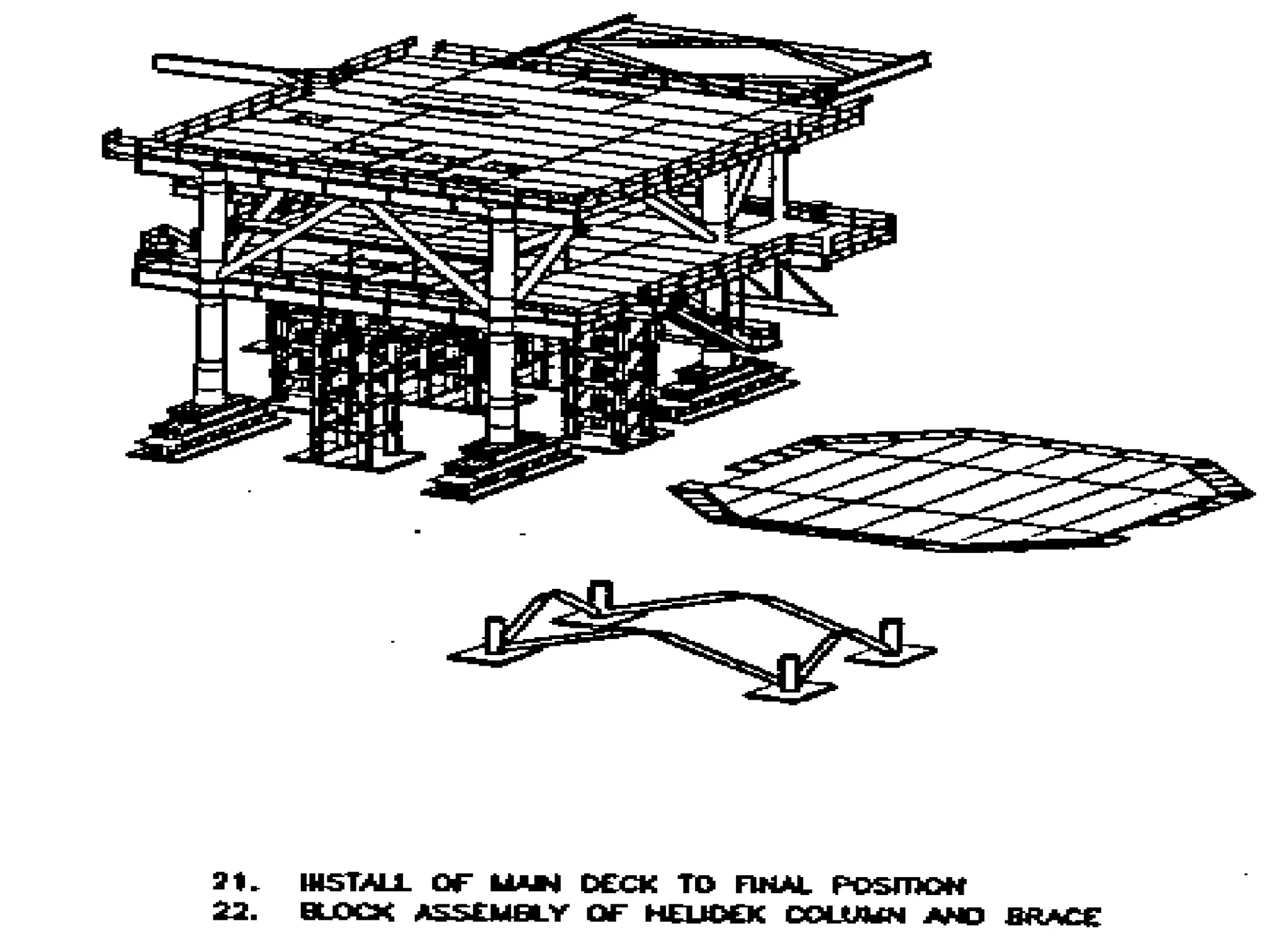
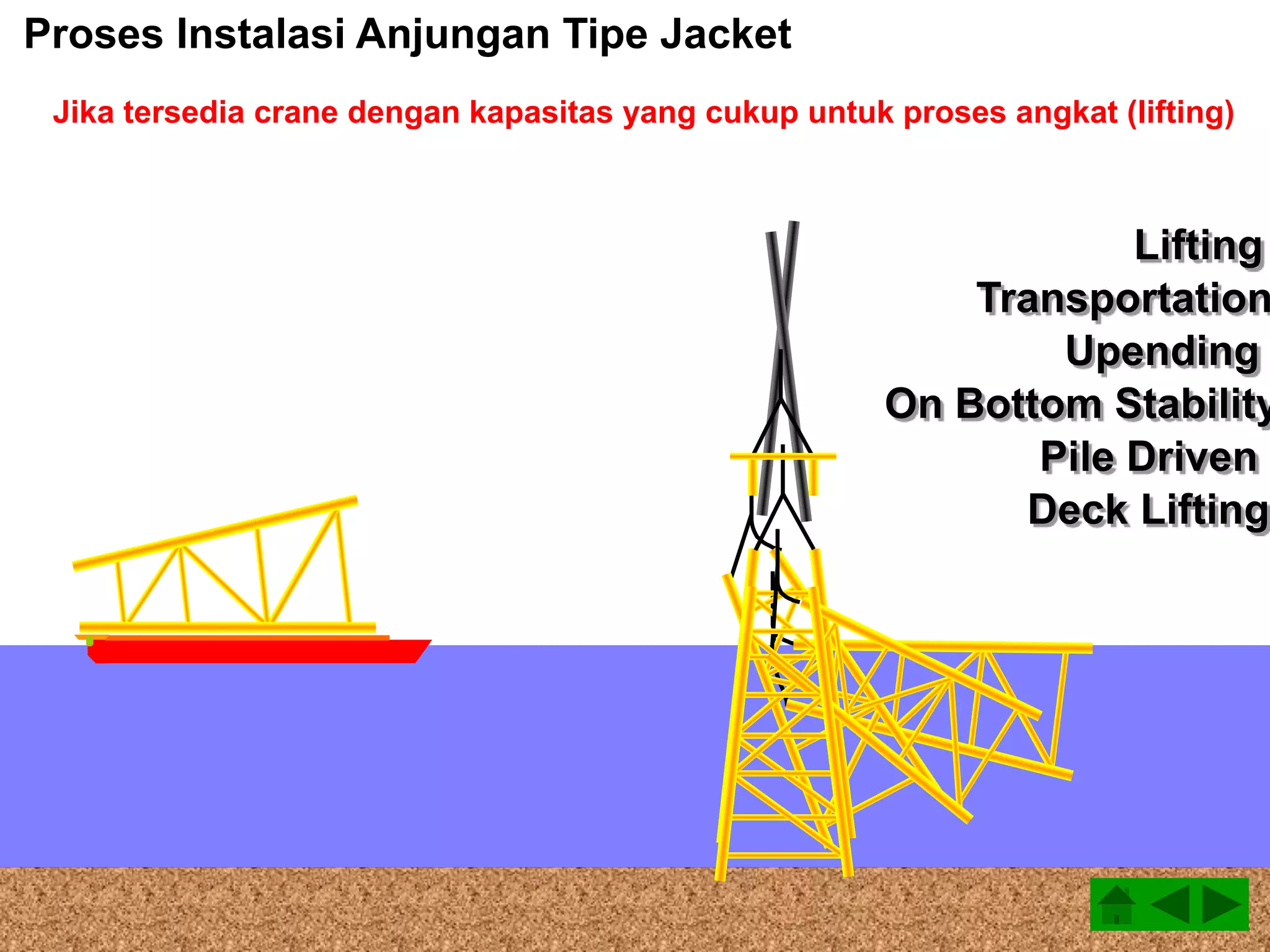
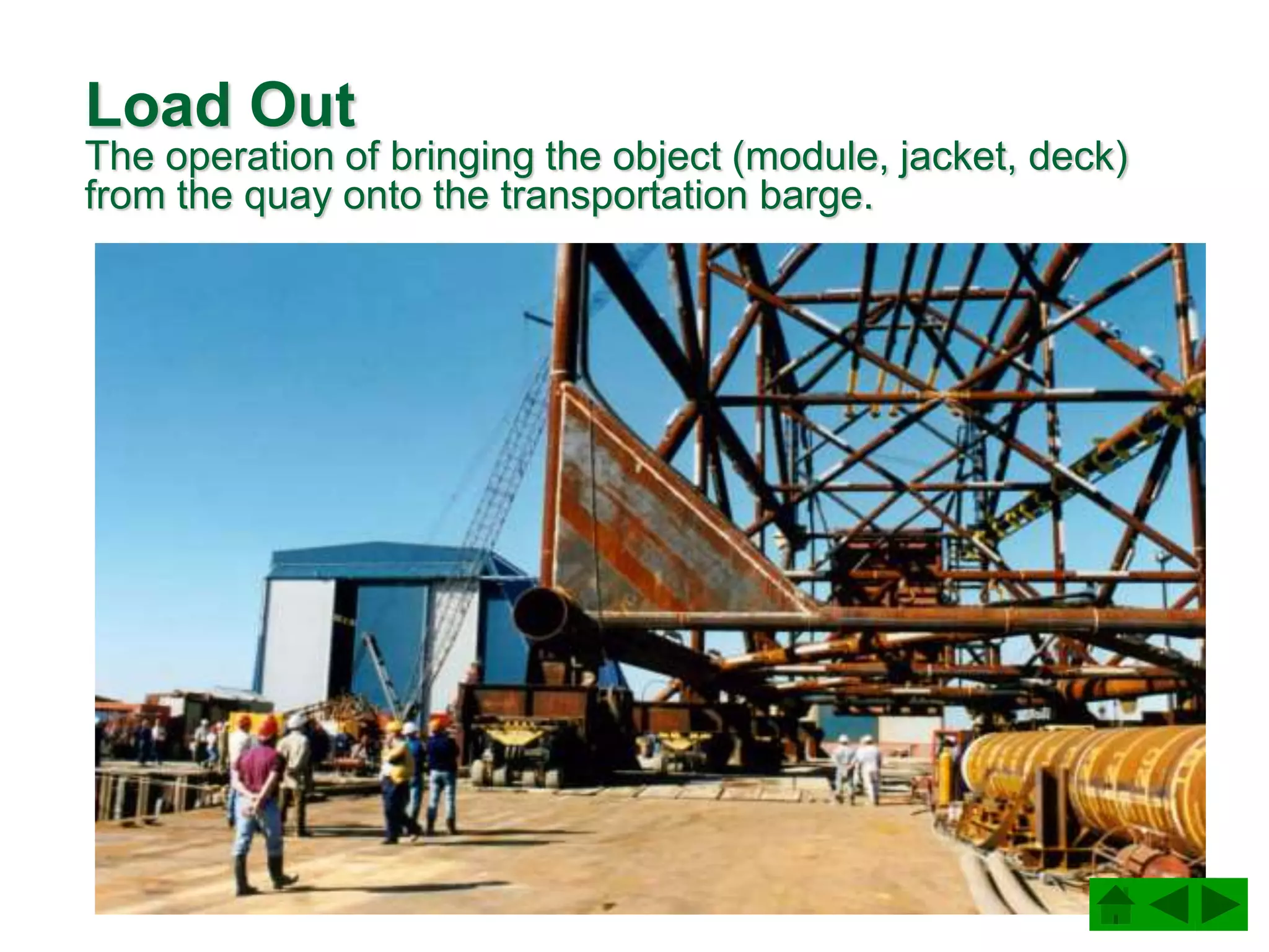
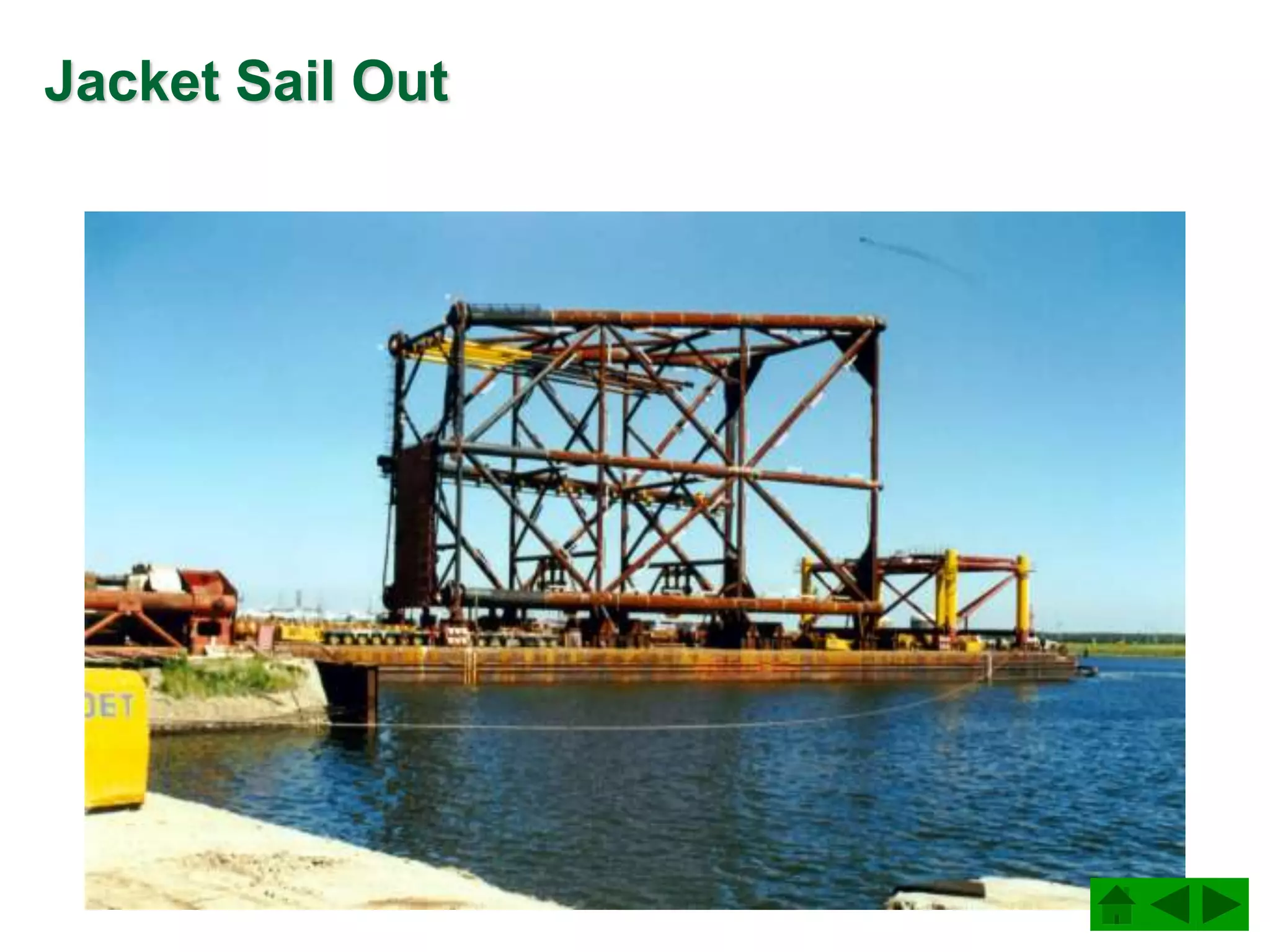
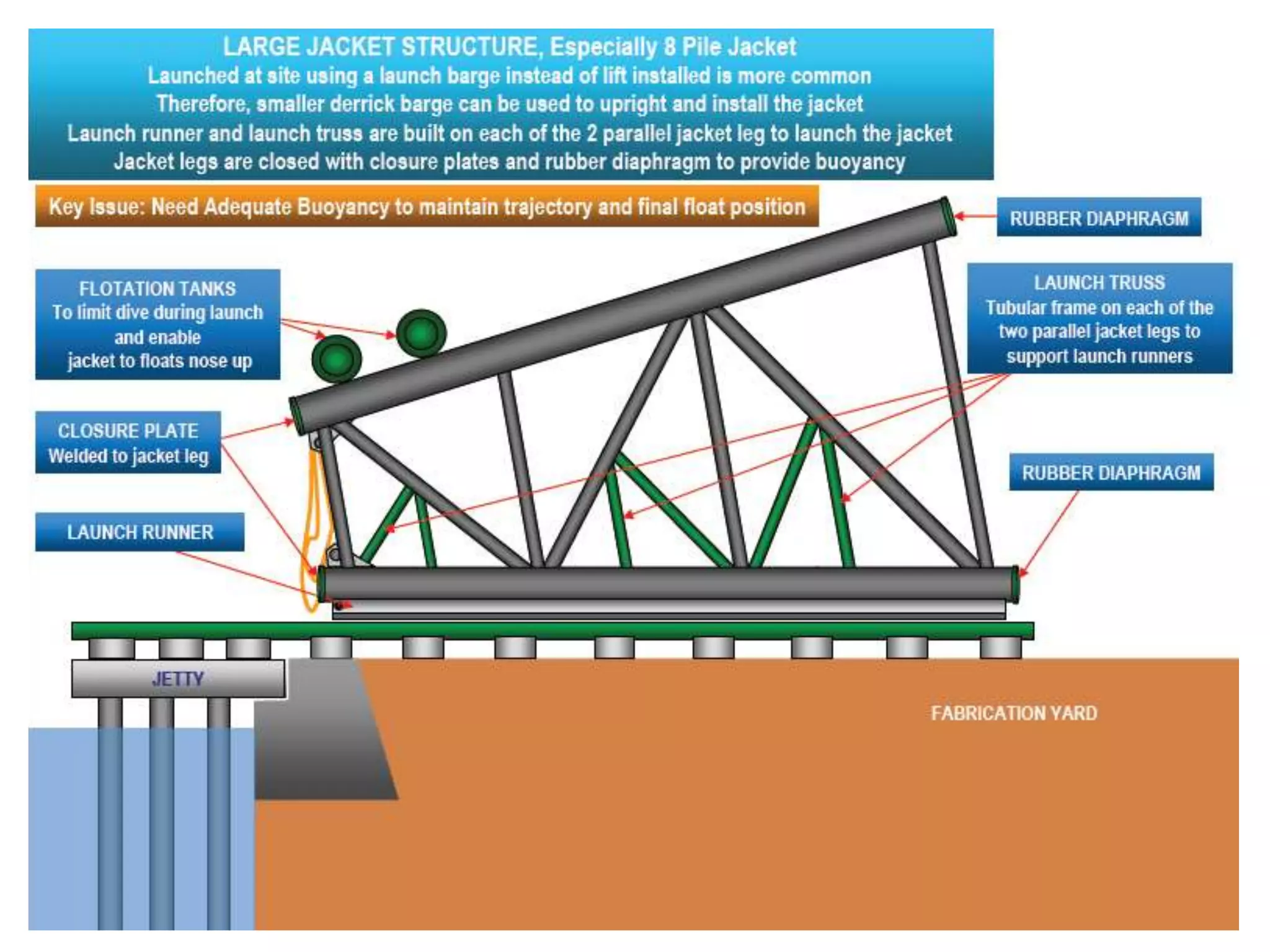
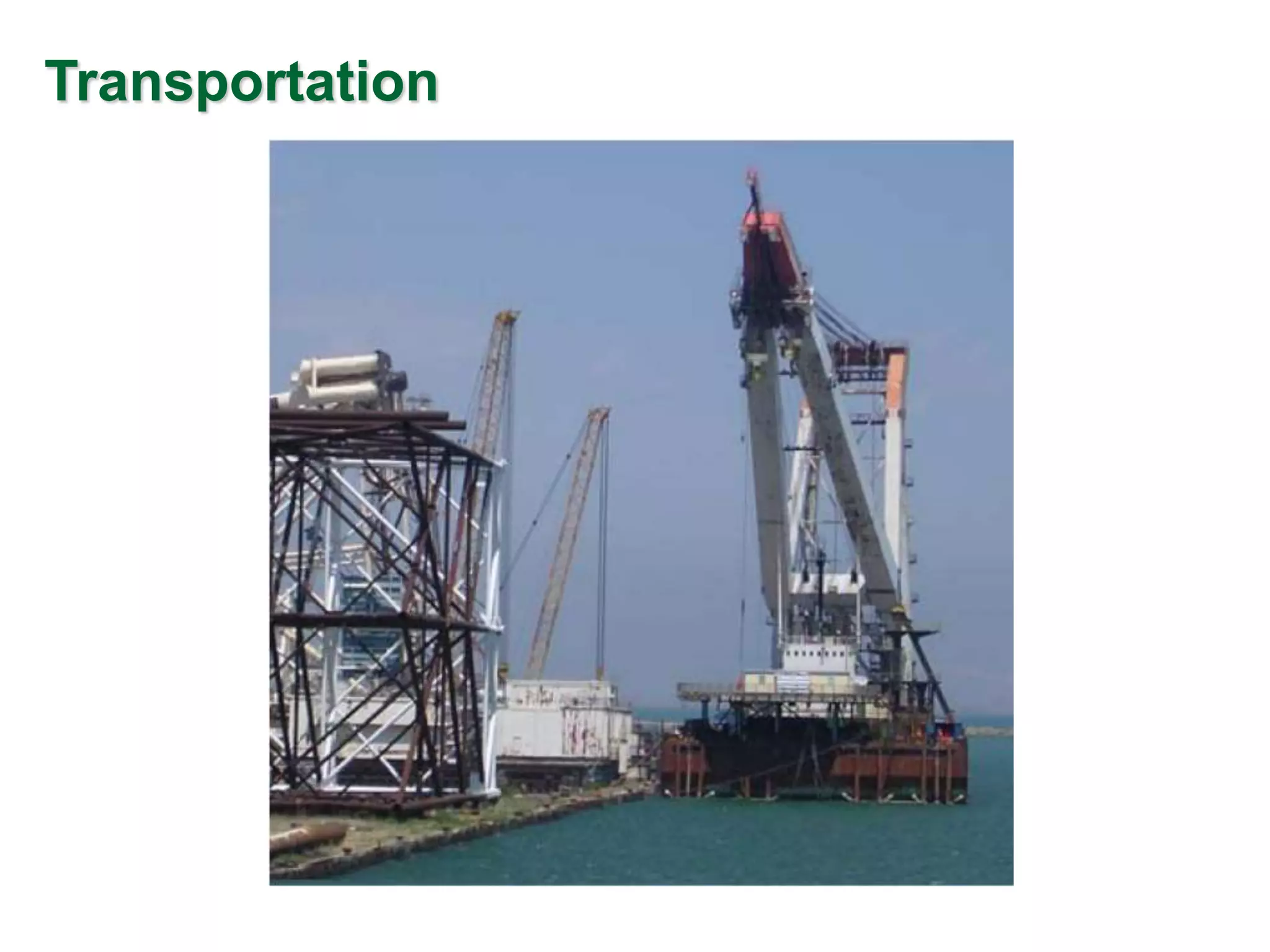
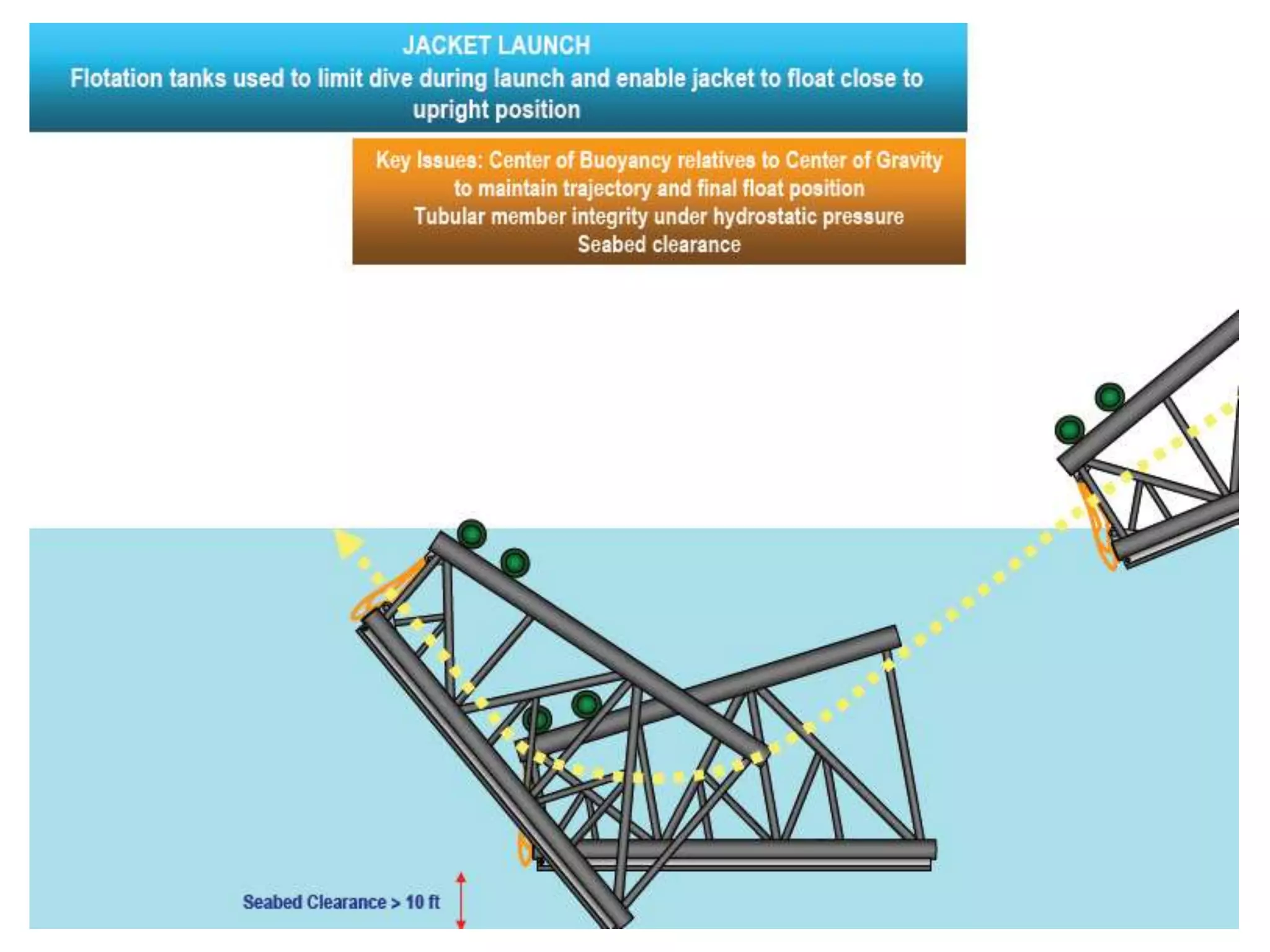
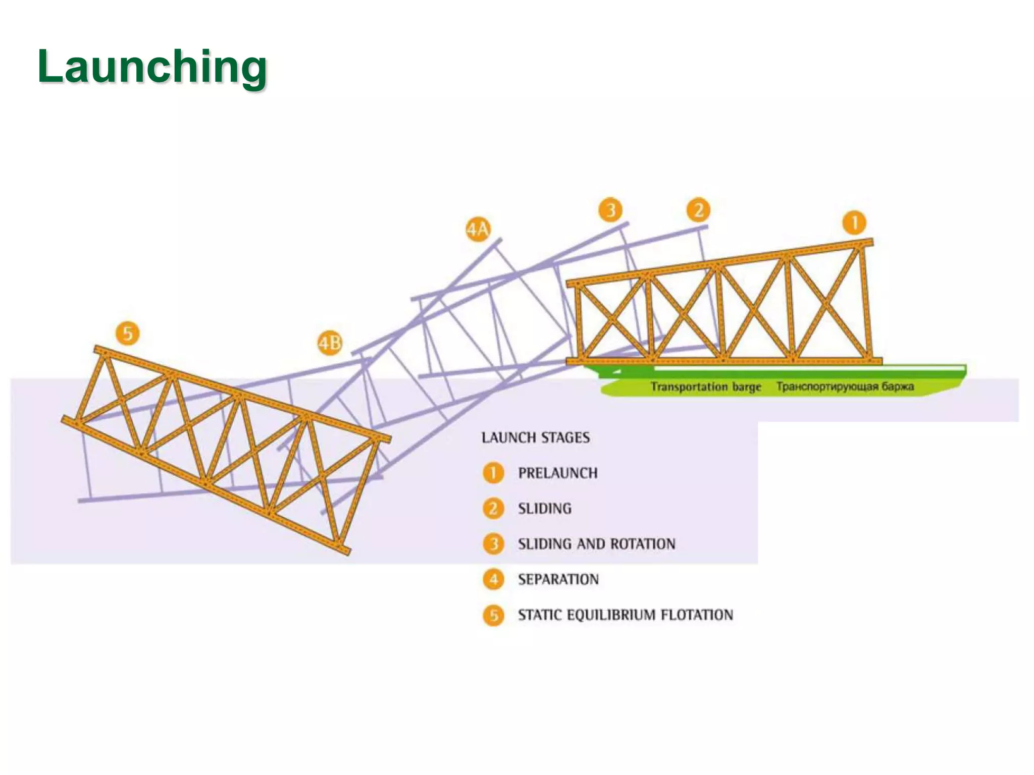
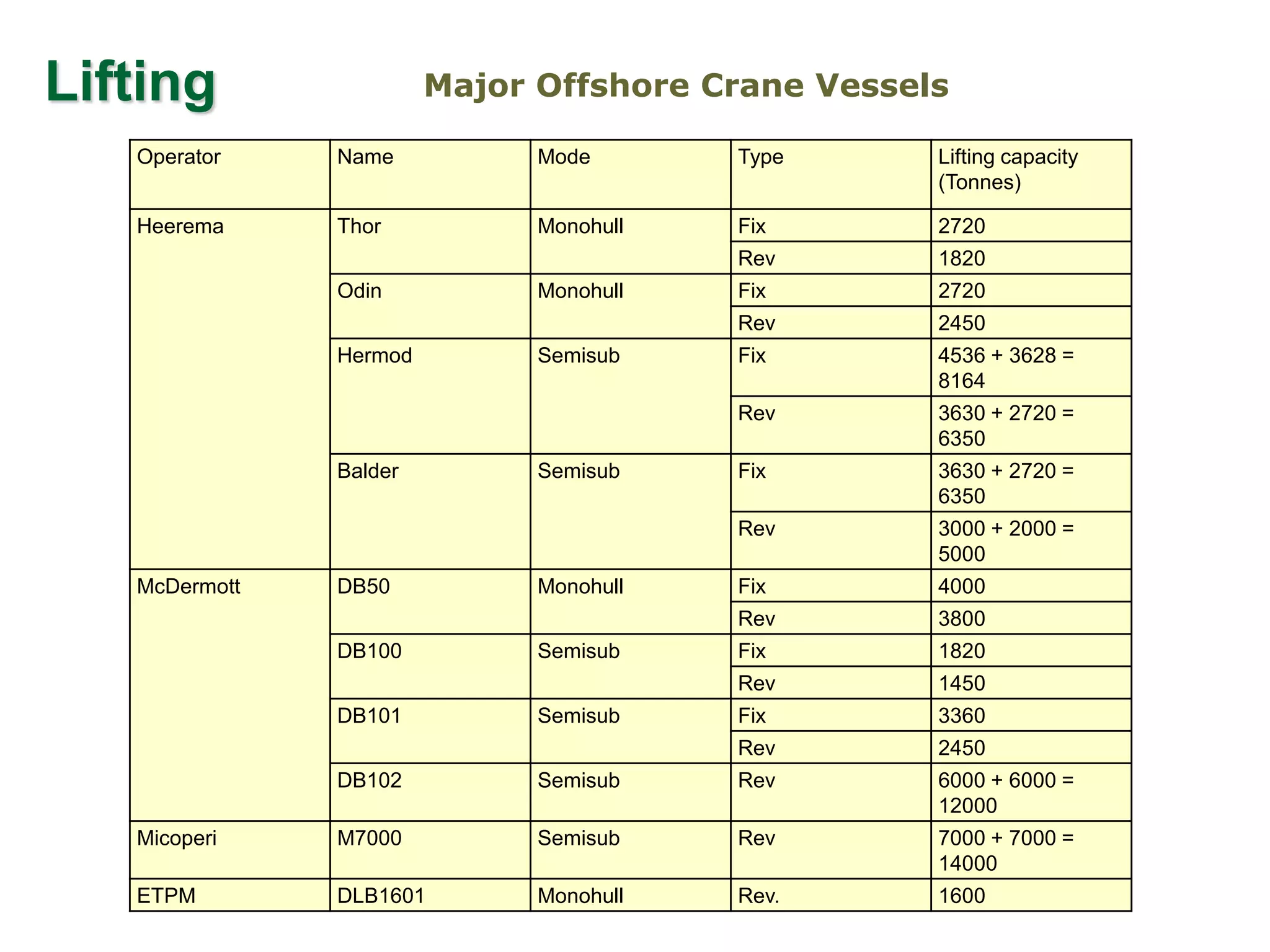
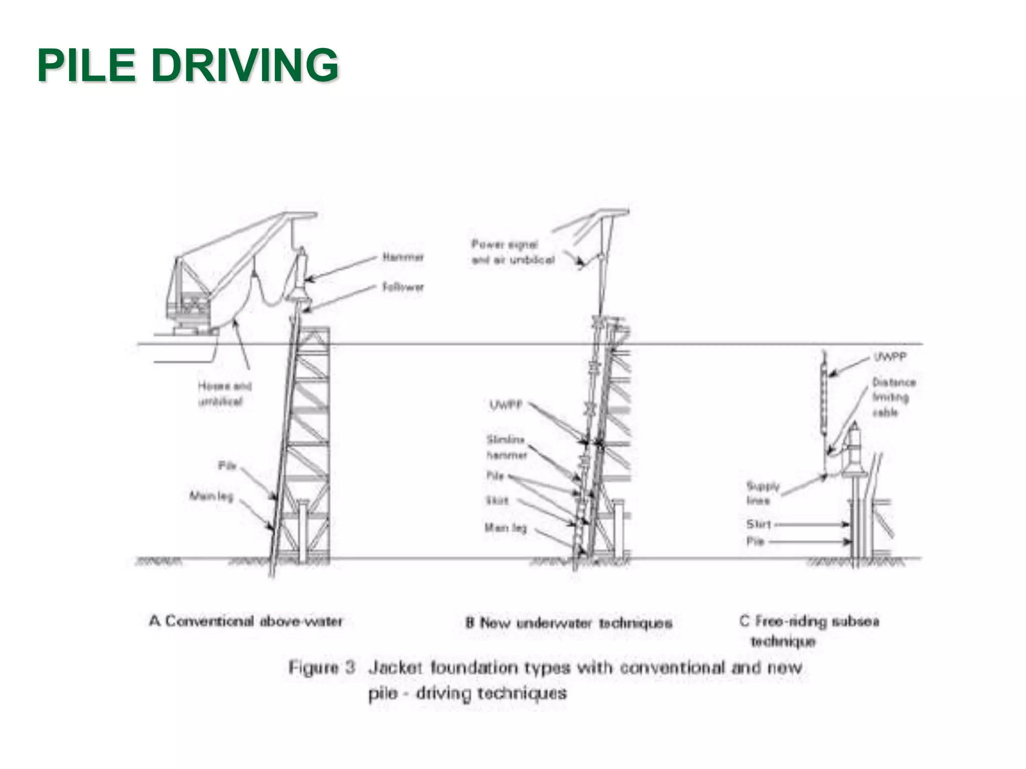
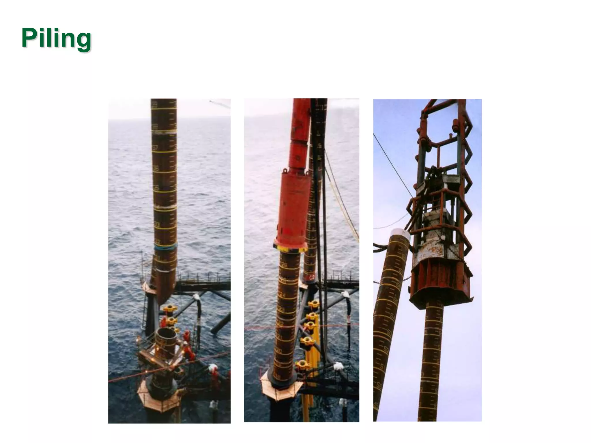
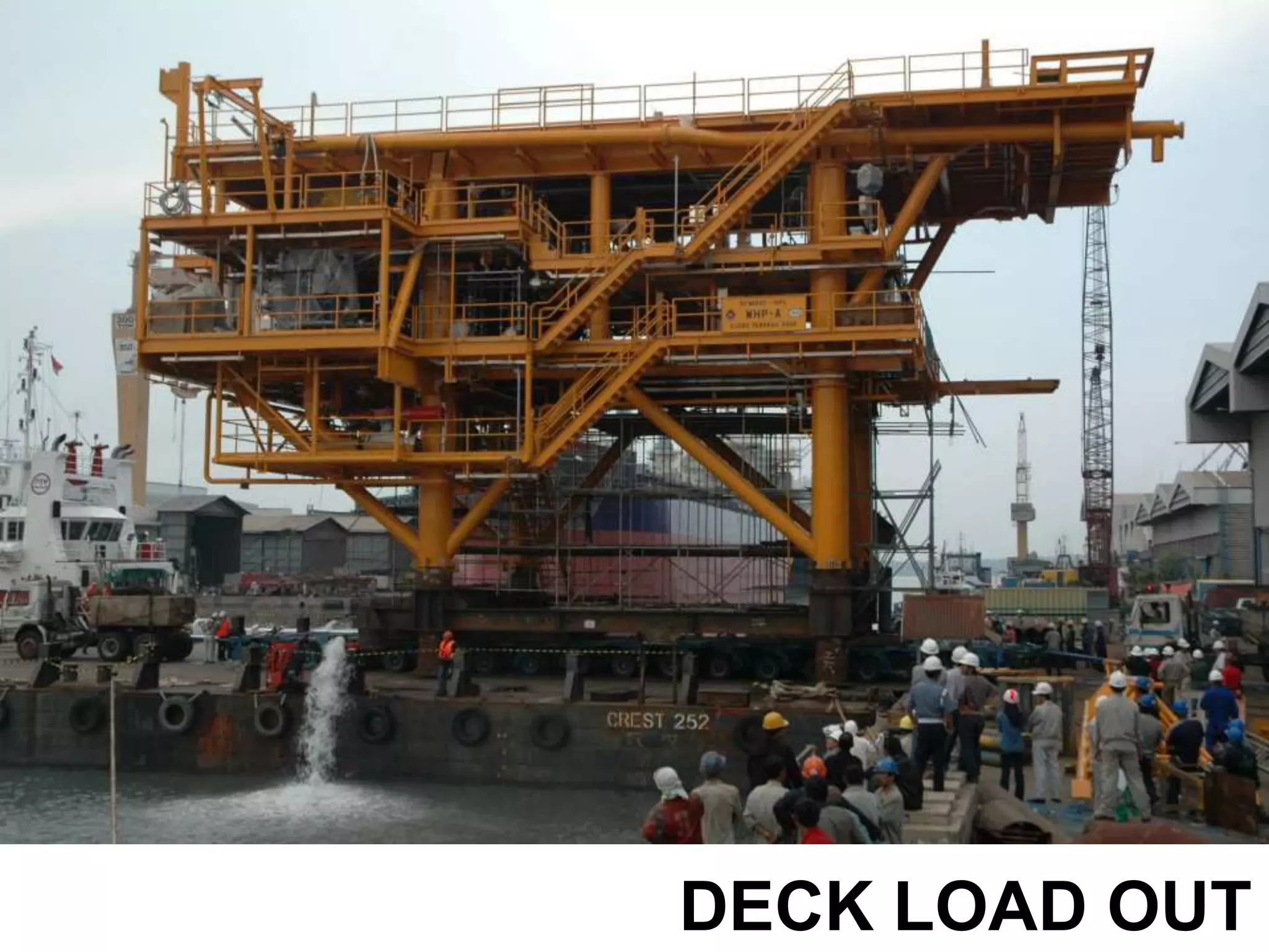
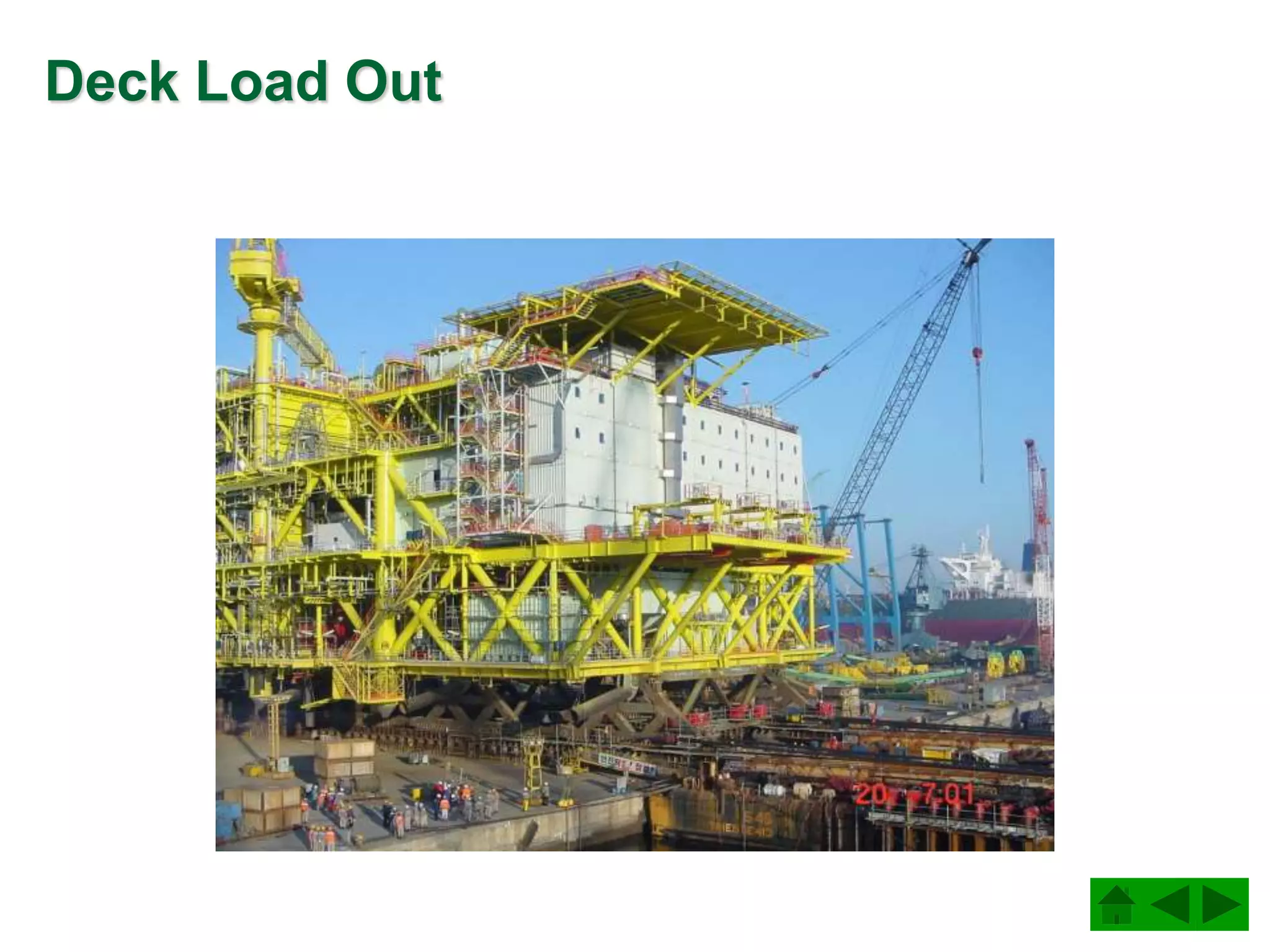
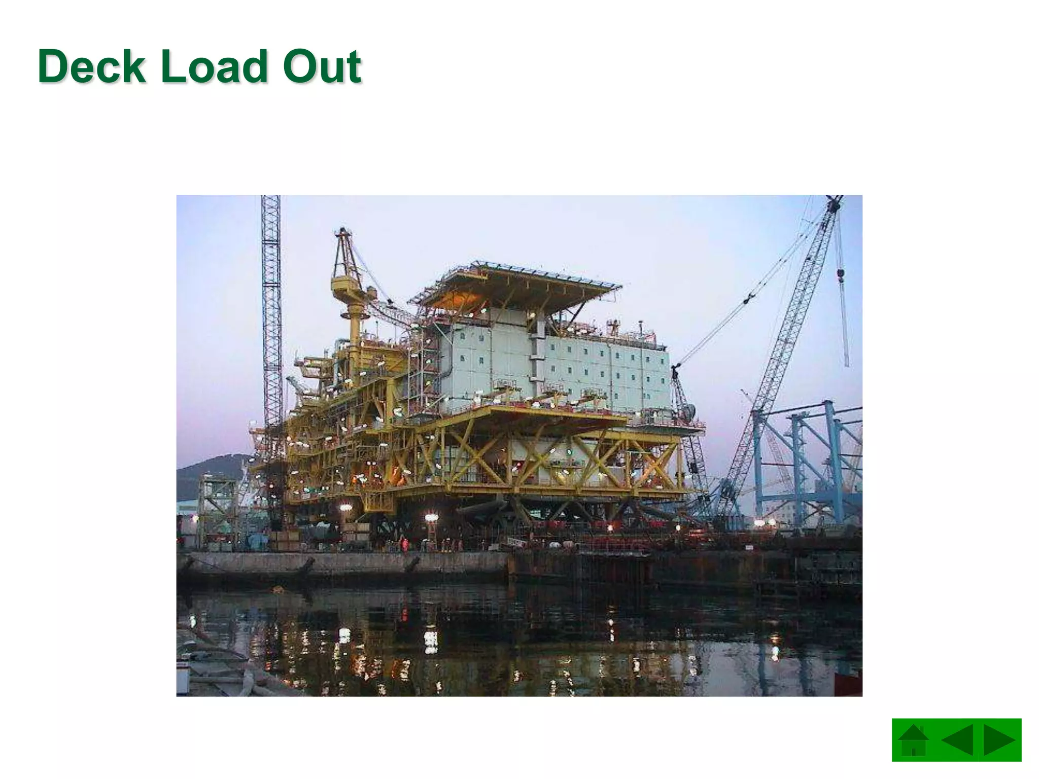
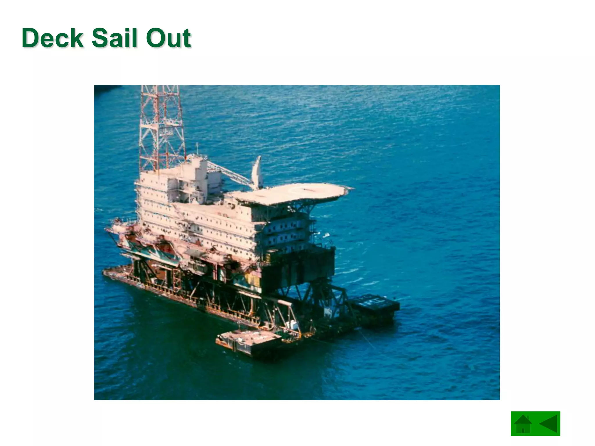
This document discusses the construction of fixed offshore platforms using steel tubular structures. It describes the key phases of fabrication and installation including fabrication of small structural units, jacket structure fabrication, jacket erection, deck fabrication, and lifting and installation of the deck and jacket. Steel tubular joints are welded together during fabrication. The jacket and deck are assembled onshore then transported offshore for installation by lifting with crane vessels. Piles are driven into the seabed to secure the jacket structure.
6. Jacket Foundation
Steel TUBULAR is widely used for
Offshore Structure due to advantages
as follows:
• CD
• CM
• Stiffness same in all directions of its
cross section
• Minimum Area need painting
• Minimum Area need CP (cathodic
protection)
• Buoyancy
7. Jacket Fabrication/Construction Phases
The processes
required to install
assembled and
shop fabricated
items together in
their final
configuration.
These processes
include fitting and
welding. However
the emphasis is
on the
transportation
and lifting of
heavy
assemblies.
Erection
The processes
normally
performed
outside the
fabrication shop
but at ground
level in order to
assemble groups
of shop fabricated
items into an
(assembled) unit
for subsequent
erection in
accordance with
a construction
sequence.
Assembly
The processes
normally carried
out in a
fabrication shop
to produce
relatively small
units. Thus
fabrication
includes
processes such
as cutting, rolling,
pressing, fitting,
welding, stress
relieving on such
items as welded
tubulars, beams,
nodes, girders,
cones, supports,
clamps, etc.
Fabrication
The technical and
commercial
activities required
to supply material
and specialised
products to
enable the
execution of
construction
activities.
Procurement
10. JACKET STRUCTURE FABRICATION
ASTM A-36, ASTM A572 Gr 50 (ROLLED PLATE to API Spec 2B)
API 5L Grade B (STEEL PIPE)
API Spec 2H for joint cans
(ROLLED STEEL PLATE to API Spec 2B)
BRACING
ANODES
Tubular members
Spiral welded pipes can not be used as per API RP2A
Tubulars D/t, local buckling
KL/r values, slenderness ratio
Welding
AWS D1.1 Section 10 for tubular structures
AWS D1.1 Section 8 for plates and structural shapes
14. JOINT CAN
• Heavy wall
• Different material
• Specifications
• Yield stress
Tubular Joints
2 inch
2 inch
15. BOTTLE JOINT CAN
• Avoid overlaps on complicated
joints
• Larger diameter
• Different material
• Specifications
• Yield stress
• May need internal stiffener rings
Tubular Joints
2 inch
2 inch
Internal stiffener rings
98. Sea Transport and Sea Fastening
• Transportation is
performed aboard a flat-
top barge or, if possible,
on the deck of the crane
vessel.
• The module requires
fixing to the barge to
withstand barge motions
in rough seas. The sea
fastening concept is
determined by the
positions of the framing
in the module as well as
of the "hard points" in
the barge.
99. Load-out
• For load-out three
basic methods are
applied:
– skidding
– platform trailers
– shearlegs.
106. LIFTING COMPONENT
SLING
PADEYES
SHACKLE
PADEYES
Thick-walled plate with hole, receiving the
pin of the shackle, welded to the main
structure.
PADEARS (TRUNNIONS)
Thick-walled tubular stubs, directly receiving
slings and transversely welded to the main
structure.
Cables with spliced eyed
at both ends, for offshore
lifting, the upper end
resting in the crane hook.
1.2 Construction Philosophy
The design of a jacket, i.e. a lifted, launched or self-floating jacket, is determined primarily by the offshore installation equipment available and the intended water depth. In general the preference is to lift the jacket in place. The size of such jackets has being increasing as offshore lifting capacity has grown. With modern lifting capacity now up to 14,000 tonnes, jackets approaching this order of magnitude are now candidates for lifting into position.
For jackets destined for shallow water, where the height is of the same order as the plan dimensions, erection is usually carried out vertically, i.e. in the same attitude as the final installation. Such jackets may be lifted or skidded onto the barge.
Jackets destined for deeper water are usually erected on their side. Such jackets are loaded by skidding out onto a barge. Historically most large jackets have been barge launched. This method of construction usually involves additional flotation tanks and extensive pipework and valving to enable the legs to be flooded for ballasting the jacket into the vertical position on site. This method of construction is currently applicable for jackets up to 25,000 tonnes. Very large jackets, in excess of this, have been constructed as self-floaters in a graving dock and towed offshore subsequent to flooding the dock.
In considering the construction philosophy and contract strategy, the objectives of achieving quality requirements and efficiency are of fundamental importance. An offshore jacket goes through a series of very distinct stages as it moves from fabrication to load-out. These stages range from operations which are almost totally automatic under very controlled conditions, e.g. steel production, automatic welding, to operations which are almost totally manual in very variable conditions, e.g. yard erection, offshore activities. Thus decreasing efficiency occurs as progress through these operations advances. In addition, the stable conditions in repetitive processes of the early operations are more conducive to the maintenance of high quality. A third basic consideration is that risk increases with each progressive stage. These general trends during construction are shown in Table 1.
It is clear therefore that, as a general principle, as much work as possible should be undertaken in the earlier more productive, higher quality, less risky phases of the project.
Some of the principles which reduce the time and cost of construction are:
Subdivision into as large components and modules as it is possible to fabricate and assemble.
Concurrent fabrication of major components in the most favourable location and under the most favourable conditions applicable to each component.
Planning the flow of components to their assembly site. Providing adequate facilities and equipment for assembly, including such items as synchrolifts, and heavy-lift cranes.
Simplification of configurations and standardisation of details, grades and sizes. Avoidance of excessively tight tolerances.
Selection of structural systems that utilise skills and trades on a relatively continuous and uniform basis. Avoidance of procedures that are overly sensitive to weather conditions; ensuring that processes which are weather sensitive are completed during shop fabrication, e.g. protective coating.
Quality management is a vital and integral component of all aspects of offshore fabrication. Essentially it involves ensuring that what is produced is what is needed. The requirements for documentation, hold point, audits, reviews and corrective actions are part of the quality assurance process. They are crucial tools for controlling the project execution and providing verifiable evidence of the fabricator's competence.
Quality control, inspection and testing should be performed during all phases of construction to ensure that specified requirements are being met. The most effective quality scheme is one which prevents the introduction of defective materials and workmanship into a structure, rather than finding problems after they occur.
A general note on Quality Assurance for Offshore Construction is included in Appendix 1. It is applicable to this lecture and also to Lecture 15A.9: Installation.
2. ENGINEERING OF EXECUTION
Engineering of execution, 'construction engineering', entails the work required during each phase of execution to ensure that the design requirements are fulfilled. A general method of execution is envisaged at the jacket design stage. Since the shape of the jacket, its form and properties require quite specific methods of load-out, offshore transportation and installation (which are construction activities executed under contractor responsibility), there is considerable interfacing of engineering requirements in these phases. In the earlier phases, i.e. procurement through assembly and erection, the contractor, while being limited by design specification requirements, has freedom of choice with regard to the exact method of execution adopted. However, in all phases the contractor is required to demonstrate that the methods which he adopts are compatible with the specification requirements and do not affect the integrity of the structure.
Each phase of execution has its own specific engineering requirements which are determined by the processes executed during that phase. These processes range from those which are largely repetitive early in execution to one-off activities in the latter phases. Accordingly the engineering which supports procurement and shop fabrication is voluminous but repetitive, e.g. material take-offs, shop drawings, cutting plans, etc. The assembly and erection phases are supported by a mix of repetitive engineering, e.g. scaffolding, and specific studies for limited series of activities.
The volume of contractor construction engineering on a large jacket is typically 130,000/150,000 hours. The typical organisation of a contractor's technical documents is shown in Table 2.
When designing larger components consideration must be given to their subdivision into elements which will not distort when fabricated and which can be relatively easily assembled without welding/dimensional problems. For instance, nodes are categorised as either complex or simple from the execution viewpoint based on the number of separate fitting-welding-NDT (non-destructive testing) cycles required during fabrication and the possibility of automatic welding between the node can and the tubular during sub-assembly. The number of fitting-welding-NDT cycles depends on the existence of ring stiffeners and the number and disposition of stubs. For reasons relating to weld distortion and to allow automatic welding, it is almost essential that ring stiffeners be installed prior to fitting/welding of stubs. This adds an extra cycle to the fabrication of the node. Thus ring stiffeners are best avoided. Where this is not possible, care should be taken to define them at an early stage on critical nodes.
Node stubs can be classified as simple or overlapping. Overlapping stubs add at least one complete cycle to node fabrication and should therefore be avoided where possible. The minimum separation between the weld toes of adjacent simple stubs is typically specified as 50mm, see API RP2A, Fig. 4.3.1-2 [1]. However this distance is too small to allow simultaneous welding of adjacent stubs - 150mm is a more practical distance.
4.1 Jacket Assembly
Shop fabricated sub-assemblies and loose items are incorporated into assemblies which constitute the major lifts of the erection sequence. Thus for a large jacket, the assemblies are typically of four types:
Jacket levels incorporating conductor guide frames
Top frames
Jacket rows i.e. bents or partial bents
Pile sleeve clusters.
The assembly and erection phases are based on the following objectives:
Maximise on-the-ground assembly (as opposed to erection) and maximise access around the jacket during execution.
Minimise erection joints in principal structural elements, such as jacket legs, launch runners, rows, levels. Align critical areas such as conductor guides, pile sleeves, launch runners.
Sub-assemble principal structural elements of jacket such as jacket legs, rows, levels. Sub-assemble, and where possible pre-test, systems such as grouting, ballasting. Include maximum quantity of secondary items such as anodes, risers, J-tubes, caissons. Coat or paint required areas (top of jacket, risers) prior to erection.
Minimise the use of temporary items which require subsequent removal, such as scaffolding, walkways, lifting aids, etc. and pre-install such aids where they are necessary.
The assembly of a jacket frame, often having a spread at the base of 50m or more, places severe demands on field layout and survey and on temporary support and adjustment bracing. Such large dimensions mean that the thermal changes can be significant. Temperature differences may be as great as 30°C between dawn and afternoon and as much as 15°C between various parts of the structure, resulting in several centimetres distortion. However, the practice of 'using the sun' to fit elements which are not dimensionally in-tolerance is common in the field. This procedure in itself tends to induce residual stresses in the structure. Because of the difficulty associated with thermal distortion, it is normal to "correct" all measurements to a standard temperature, e.g. 20° C.
Elastic deflections are also a source of difficulty in maintaining tolerances in the location of nodes. Foundation displacements under the skid beams and temporary erection skids must be carefully calculated and monitored.
The overall assembly sequence and programme requires that each assembly be completed prior to lifting. It is normal to determine the exact location, orientation and attitude, i.e. face-up or face-down, of each assembly in the field in anticipation of its lifting procedure.
Assembly layout drawings are usually prepared showing central co-ordinates for each assembly. The central co-ordinates are then used as local bench marks with the object of defining the assembly, the sub-assemblies, loose items, appurtenances and temporary attachments which comprise, field welds, overall dimensions, weight, reference drawings, etc.
Dimensional control of the assembly both prior to and after welding, can be by means of a series of self-checking measurements on the structure itself. Provided cross checks are adequate, the time consuming exercise of referring measurements to an external bench mark can be avoided.
Normally the assembly is tacked in position to theoretical dimensions using allowable positive tolerances to compensate for weld shrinkage. Perhaps the most fundamental rule in fitting is the avoidance of "force-fitting" of members prior to welding or to force stresses into unwelded members through the welding sequence since such conditions cannot have been foreseen by the designer.
An outline sequence of events which apply to all types of assembly is as follows:
Preparation of assembly support and staging
Rough setting of assembly main structure and position tacking. Dimensional control of assembly main structure.
Infilling of secondary structure and position tacking. Dimensional control of assembly and secondary structure.
Preweld inspection. Weldout of structure subject to continuous inspection and according to approved sequence.
Installation of appurtenances (e.g. anodes, supports, walkways, risers, J-tubes, caissons, grouting and ballasting) and scaffolding, lifting, aids, erection guides, temporary attachments.
Test (e.g. hydrotest) if required. Overall NDT, dimensional control.
Blasting and painting or touch up. Removal of temporary assembly supports and staging.
Preparation for transport/lift/erection.
4.4 Jacket Erection
In this phase assembled, sub-assembled and fabricated structures, together with loose items, are incorporated into the final structure according to the sequence outlined in Figure 3a - 3e.
Jacket frames are typically laid out flat and then rolled using multiple crawler cranes. Co-ordinating such a rigging and lifting operation requires thoroughly developed three-dimensional layouts, firm and level foundations for the cranes and experienced, well rehearsed operators.
Twenty four cranes were involved in the two major side frame lifts during the erection of platform Cerveza, which was 300m long.
For the Magnus platform and Bouri DP3, a different procedure known as "toast rack" was used. Here the jacket horizontal levels were fabricated, erected in place and tied in to complete the jacket.
For the Bullwinkle jacket, one of the world's largest, sections of the jacket were fabricated in Japan, transported by barge to Texas and assembled using jacking towers which rolled up the sections to heights as great as 140m.
For jackets destined for shallow water erection is usually carried out vertically, i.e. in the same attitude as the final installation. Such jackets may be lifted onto the barge or skidded out. In this latter case, adequate temporary pads and braces must be provided under the columns to distribute the loads for skidding.
The structural analysis associated with the erection procedure for a given assembly usually involves a computer model with all relevant structural characteristics. The assembly is analysed for a number of load cases which correspond (approximately) to the support conditions of the assembly at its presumed critical attitudes, i.e. the locations of the cranes, bogies, saddles, etc. when the panel is being transported and when it is in horizontal and vertical attitudes. The structural analysis for lift/transport identifies the worst cases from the point of view of structural response. These cases are then analysed to determine the maximum stresses and displacements. The calculations should show that global and local stresses are within allowable limits according to API/AISC codes.
Frequently, a structural analysis computer programme is used for this purpose. The analysis will indicate where bending stresses are high and/or crane, bogie or support loads inadmissible. Thus modifications can be made to redistribute structural stresses and loads at "supports" to optimise both and ensure that neither the cranes nor the structure can be overloaded during erection.
An outline sequence for the erection of all major components would be:
Technical appraisal of lift methods. Calculations for crane configuration, rigging accessories, etc.
Preparation of cranes for lift. Preparation for rigging. Transport assembly to lift location. Roll-up into position with scaffolding and staging in position, if possible.
Preparation of fixing system and wind bracing (usually done by means of guy wires and turnbuckles). Weldout at least sufficient to allow crane release.
Crane release. Removal of rigging and temporary attachments.
Jacket structural completion is followed by a short phase during which all the jacket systems, both permanent and those required during installation, are completed and rendered functional. The load-out operations are covered in Lecture 15A.9: Installation.
After items to be welded together have been positioned as required, generally by clamping them on suitable fixtures, tack welds are used as a temporarymeans to hold the components in the proper location, alignment, and distance apart, until final welding can be completed.
LC Crane: Larry Collier Crane
Very large jackets, in excess of launch capacity, have been constructed as self-floaters in a graving dock, towed offshore subsequent to flooding the dock, and installed on location by means of controlled flooding of the legs (see Figure 4).
4.2 Jacket Up-ending and Set-down
Unless a jacket is transported and lifted in its upright position, it will be necessary to up-end the jacket at the installation location. Up-ending may be achieved by controlled flooding of buoyancy tanks, by using a crane vessel or by a combination of both.
4.2.1 Up-ending by Ballast control and Flooding
A large crane vessel will not normally be required for either a launched or self-floating jacket. Upending is therefore achieved by controlled flooding. A small installation vessel will usually be required for the installation of piles once the jacket has been set-down, so this is used as the platform from which to control the various flooding operations. This installation vessel will also be used to help position the jacket.
Figure 3 shows a sketch of the Brae 'B' jacket showing the auxiliary buoyancy tanks. In this case the flooding system involved 42 primary and 22 contingency subsea valves under direct hydraulic control. The nitrogen power source and associated control panels were contained in watertight capsules.
Figure 4 shows a sequence of sketches indicating how a self floating jacket is upended. In step 1 the waterline compartments at one end of the jacket are flooded. More water line tanks are flooded in step 2 until by step 3 the upper frame of the jacket reaches waterline and may also be flooded. The jacket is then allowed to rotate until all legs are equally flooded as in step 4. The jackets natural position will then be floating upright as in step 5. Further flooding of the jacket as in step 6 will enable the jacket to be lowered onto the sea bed in a controlled manner.
The up-ending of a launched jacket will be similar to that shown in Figure 4. The main difference is that there may be less excess buoyancy with which to control the operation. In this case a combination of flooding and lift, as shown in Figure 5, may be used to up-end and set-down the jacket.
The crane and ballasting operations need to be clearly defined before the operation begins. This involves careful naval analysis of the free floating position of the jacket at various stages during the up-ending procedure. A feature of these analyses is the need to consider what happens in the event of buoyancy tanks being accidentally flooded, or of flooding valves failing to operate. Contingency procedures and equipment must be provided.
4.2.2 Up-ending using the crane vessel
Figure 5 shows the most simple use of a crane to up-end and set-down a jacket. This is acceptable for jackets that are launched. For horizontally oriented jackets that are lifted directly the procedure is more involved.
A horizontally lifted jacket may be upended in one of two ways. Perhaps the most straight forward is to lower the jacket into the water so that it floats. Slings can then be removed and new slings attached at the top of the jacket. The jacket may then be up-ended as shown in Figure 5. This may require closures to legs and some additional buoyancy.
A second method is to up-end directly, as shown in Figure 6. This requires special padears so that the necessary rotation between slings and jacket can occur. Careful naval analysis is also required in order to carefully determine hook loads and to ensure that the jacket remains stable.
Once up-ended the jacket can be set-down on the sea-bed. Since the lifting points are submerged divers may be required to disconnect the slings from the jacket.
Although two crane hooks are shown in Figure 6, it should be noted that for light weight jackets it is possible to up-end using a single crane. In this case the main and auxiliary hooks are used together, for example the main hook taking the weight of the jacket with the auxiliary hook providing the upending force.
An increasing trend is to install a jacket over an existing well or wells. A pre-drilling template will have been used to position the wells, the same template being used to position the jacket. It is necessary to ensure that the well heads are protected from damage due to accidental contact with the jacket.
Once set-down the jacket should be positioned at or near grade and levelled within the tolerances specified in the installation plan. Once level, care should be exercised to maintain grade and levelness of the jacket during subsequent operations. Levelling the jacket after all piles have been installed should be avoided if at all possible as it is costly and frequently ineffective. If necessary, levelling should take place after a minimum number of piles have been driven by jacking or lifting. In this instance procedures should be used to minimise bending stresses in the piles.
The jacket is built in horizontal position.
For load-out to the transport barge, the jacket is put on skids sliding on a straight track of steel beams, and pulled onto the barge (Slide 5).
7.5.2 Skidding
Skidding is a method feasible for items of any weight. The system consists of a series of steel beams, acting as track, on which a group of skids with each approximately 6 MN load capacity is arranged. Each skid is provided with a hydraulic jack to control the reaction.
7.5.3 Platform Trailers
Specialized trailer units (see Figure 10) can be combined to act as one unit for loads up to 60 - 75 MN. The wheels are individually suspended and integrated jacks allow adjustment up to 300 mm.
The load capacity over the projected ground area varies from approximately 55 to 85 kN/sq.m.
The units can drive in all directions and negotiate curves.
7.5.4 Shearlegs
Load-out by shearlegs is attractive for small jackets built on the quay. Smaller decks (up to 10 - 12 MN) can be loaded out on the decklegs pre-positioned on the barge, thus allowing deck and deckleg to be installed in one lift offshore.
At the offshore location the jacket is slid off the barge. It immerses deeply into the water and assumes a floating position afterwards (see Figure 6).
Two parallel heavy vertical trusses in the jacket structure are required, capable of taking the support reactions during launching. To reduce forces and moments in the jacket, rocker arms are attached to the stern of the barge.
The next phase is to upright the jacket by means of controlled flooding of the buoyancy tanks and then set down onto the seabed. Self-upending jackets obtain a vertical position after the launch on their own. Piling and pile/jacket fixing completes the installation.
For topsides up to approximately 120 MN, the topside may be installed in one lift. Slide 6 shows a 60 MN topside being installed by floating cranes.
For the modularized topside, first the MSF will be installed, immediately followed by the modules.
Lifting of heavy loads offshore requires use of specialized crane vessels. Figure 7 provides information on a typical big, dual crane vessel. Table 1 (page 16) lists some of the major offshore crane vessels.
For lifting, steel wire ropes in a four-sling arrangement are used which directly rest in the four-point hook of the crane vessel, (see Figure 8). The heaviest sling available now has a diameter of approximately 350 mm, a breaking load of approximately 48 MN, and a safe working load (SWL) of 16 MN. Shackles are available up to 10 MN SWL to connect the padeyes installed at the module's columns. Due to the space required, connecting more than one shackle to the same column is not very attractive. So when the sling load exceeds 10 MN, padears become an option.
Notes:
Rated lifting capacity in metric tonnes.
When the crane vessels are provided with two cranes, these cranes are situated at the vessels stern or bow at approximately 60 m distance c.t.c.
3. Rev = Load capability with fully revolving crane.
Fix = Load capability with crane fixed.