Catalog mikro mikro mu2300
•
0 likes•31 views

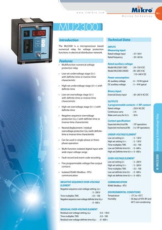
The MU2300 is a microprocessor-based numerical relay for voltage protection in electrical distribution networks. It provides multifunction voltage protection with low-set and high-set undervoltage and overvoltage stages with definite or inverse time characteristics. It can operate in single or three-phase configuration and includes features such as fault recording, output contacts, and Modbus RTU communication.

Recommended
More Related Content
What's hot
What's hot (16)
Similar to Catalog mikro mikro mu2300
Similar to Catalog mikro mikro mu2300 (20)
More from Dien Ha The
More from Dien Ha The (20)
Recently uploaded
Recently uploaded (20)
Catalog mikro mikro mu2300
- 1. Introduction The MU2300 is a microprocessor based numerical relay for voltage protection functions in electrical distribution network. Features • Multifunction numerical voltage protection relay • Low-set undervoltage stage (U<) with definite-time or inverse-time characteristic • High-set undervoltage stage (U<<) with definite-time • Low-set overvoltage stage (U>) with definite-time or inverse-time characteristic • High-set overvoltage stage (U>>) with definite-time • Negative sequence overvoltage protection (U2>) with definite-time or inverse-time characteristic • Neutral displacement / residual overvoltage protection (U0>)with definite- time or inverse-time characteristic • Can be used in single-phase or three- phase operation • Multi-function isolated digital input with wide input voltage range • Fault record and event code recording • Five programmable voltage-free output contacts • Isolated RS485 Modbus - RTU communication Overvoltage&UndervoltageRelayMU2300 MU2300 Technical Data INPUTS Measuring input: Rated voltage input : 57-130V Rated frequency : 50 / 60 Hz Rated auxiliary voltage: Model MU2300-150D : 24~150V DC Model MU2300-240AD : 85~265V AC 110~340V DC Power consumption: AC auxiliary voltage : 6 ~ 10VA typical DC auxiliary voltage : 5 ~ 9W typical Binary Input: External binary input : 85~265V AC/DC OUTPUTS 5 programmable contacts +1 IRF contact: Rated voltage : 250V AC/DC Continuous carry : 5 A Make and carry for 0.2 s : 30 A Contact specification: Expected electrical life : 105 operations Expected mechanical life : 5 x 10⁶ operations UNDER-VOLTAGE ELEMENT Low set setting U< : 5 - 130V High set setting U<< : 5 - 130V Time multiplier,TMS : 0.5 - 100 Low set Definite time tU< : 0 - 600 s High set Definite time tU<< : 0 - 600 s OVER-VOLTAGE ELEMENT Low set setting U> : 5 - 200V High set setting U>> : 5 - 260V Time multiplier,TMS : 0.5 - 100 Low set definite time tU> : 0 - 600 s High set definite time tU>> : 0 - 600 s COMMUNICATION RS485 Modbus - RTU ENVIRONMENTAL CONDITIONS Temperature : -5˚C to +55˚C Humidity : 56 days at 93% RH and 40˚C non-condensing NEGATIVE SEQUENCE OVER-VOLTAGE ELEMENT Negative sequence over-voltage setting, U2> : 5 - 200V Time multiplier,TMS : 0.5 - 100 Negativesequenceover-voltagedefinitetimetU2> : 0 - 600 s RESIDUALOVER-VOLTAGEELEMENT Residual over-voltage setting, U0> : 0.5 - 130V Time multiplier,TMS : 0.5 - 100 Residual over-voltage definite time tU0> : 0 - 600 s
- 2. Overvoltage&UndervoltageRelayMU2300 11 1010 100100 00 0.10.1 0.20.2 0.30.3 0.40.4 0.50.5 0.60.6 0.70.7 0.80.8 0.90.9 11 TMS=1 TMS=5 TMS=3 TMS=10 TMS=8 Applied voltage/relay setting voltageApplied voltage/relay setting voltage Operatingtime(sec)Operatingtime(sec) UNDERVOLTAGE CHARACTERISTIC 0.01 0.1 1 10 100 0 2 4 6 8 10 12 14 16 18 20 TMS=1 TMS=8 TMS=10 TMS=5 TMS=3 Applied voltage/relay setting voltageApplied voltage/relay setting voltage Operatingtime(sec)Operatingtime(sec) OVERVOLTAGE CHARACTERISTIC 142 mm 165mm Front 129 1 mm 1391mm Panel Cutout 198 mm 34 mm 136mm Side TYPICAL APPLICATION DIAGRAMS CASE DIMENSIONS 3 2 6 5 9 8 12 11 31 32 33 13 14 34 36 35 38 37 40 39 42 41 27 26 28 30 29 25 24 22 23 External Digital Input Uaux R1 R2 R3 R4 R5 A B C Trip Contact A BC Phase rotation Internal Relay Failure TerminationResistor N- P+ Communication CableShield Ordering Information MU2300-150D For 50 / 60 Hz system, auxil- iary voltage 24 ~ 150 V DC MU2300-240AD For 50 / 60 Hz system, auxiliary voltage 85 ~ 265 V AC or 110~340 V DC MODEL DESCRIPTION 3 2 6 5 9 8 12 11 31 32 33 13 14 34 36 35 38 37 40 39 42 41 27 26 28 30 29 25 24 22 23 External Digital Input Uaux R1 R2 R3 R4 R5 A B C Trip Contact A BC Phase rotation Internal Relay Failure TerminationResistor N- P+ Communication CableShield 3 2 6 5 9 8 12 11 31 32 33 13 14 34 36 35 38 37 40 39 42 41 27 26 28 30 29 25 24 22 23 External Digital Input Uaux R1 R2 R3 R4 R5 A B C Trip Contact A BC Phase rotation Internal Relay Failure TerminationResistor N- P+ Communication CableShield 3 2 6 5 9 8 12 11 31 32 33 13 14 34 36 35 38 37 40 39 42 41 27 26 28 30 29 25 24 22 23 External Digital Input Uaux R1 R2 R3 R4 R5 A B C Trip Contact A BC Phase rotation Internal Relay Failure TerminationResistor N- P+ Communication CableShield 3Vp-p + Vresidual connection 2Vp-p + Vresidual connection 3Vp-n + Vresidual connection 3Vp-n connection