2.
Committed to be better power!
++++General
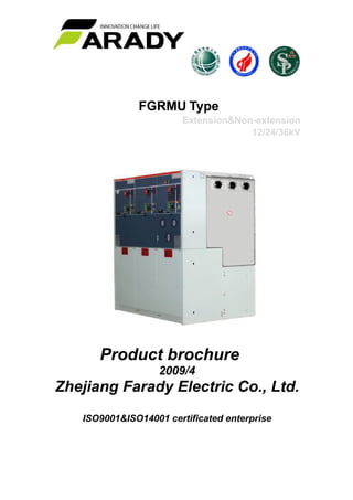
FGRMU is a ring main unit for the secondary distribution network. FGRMU can be supplied in
10 different configurations suitable for mostswitching applications in 12/24 kV distribution
networks. It is extendable and combined with the SafePlus concept, which is ABB’s flexible,
modular compact switchgear, they represent a complete solution for 12/24 kV secondary
distribution networks. FGRMU and SafePlus have identical user interfaces. FGRMU is a
completely sealed system with a stainless steel tank containing all live parts and switching
functions. A sealed steel tank with constant atmospheric conditions ensures a high level of
reliability as well as personnel safety and a virtually maintenance-free system. The FGRMU
concept offers a choice of either switch-fuse combination or circuit-breaker with relay for
protection of the transformer. FGRMU can be supplied with an integrated remote control and
monitoring unit.
This product is in conformity with the standards of IEC60420, GB/T11022, GB3804,GB3906
++++Service environment
a) Air temperature:Maximum temperature: +40℃; Minimum temperature:-20℃
b) Humidity:Monthly average humidity 95%; Daily average humidity 90% .
c) Altitude above sea level:Maximum installation altitude: 2500m
d) Ambient air not apparently polluted by corrosive and flammable gas, vapor etc.
e) No frequent violent shake
++++Standard combination and its weight, dimension
Standard combination and its weight, dimension
2 units DF (260kg) 700×750×1345mm 3 units CCC (300kg) 1020×750×1345mm
3.
4 units CCCC (390kg)1350×750×1345mm 5 units CCCCC (480kg) 1670×750×1345mm
2 units DV (252kg) 700×750×1345mm 3 units CCF (320kg)1020×750×1345mm
4 units CCCF (410kg)1350×750×1345mm 5 units CCFFF (540kg) 1670×750×1345mm
2 units CF (270kg) 700×750×1345mm 3 units CFC (320kg) 1020×750×1345mm
4. 4 units CCFF (430kg)1350×750×1345mm 5 units CCVVV (509kg) 1670×750×1345mm
Note: we can provide with the RMU according to Special requirement order.
++++ Standard instruction
D unit configuration
See standard configuration and features of "Cable connecting module without earth switch
module"
C unit configuration
See standard configuration and features of "Load break switch module"
F unit configuration
See standard configuration and features of "Load break switch and fuse combination module"
V unit configuration
See standard configuration and features of " Vaccum switch module"
++++Standard combinations also includes belowing configurations
Voltage indicator of incoming bushing capacitive character
SF6 density/pressure monitor( gas meter) with each gas cell
Ring for lifting
Operating handle
++++ Main technical specifications
No
Item Unit
C Module V Module
Load Break Switch Circuit Breaker
1 Rated voltage kV 12 24 12 24
2 Rated current A 630
3 Rated frequency Hz 50/60
4 1min Power frequency withstand
voltage
kV
45 55 45 55
5 Lightning impulse withstand voltage kV 75 125/150 75 125/150
6 Rated transfer current A 1700 1400
7 Rated active load and close circuit
breaking current
A 630
5.
8 Rated cable charge breaking current A 50&10
9 Rated short circuit breaking current kA 20 16
10
Rated short circuit making current
(peak)
kA
63
50
63
50
11 Short time (2s) withstand current, load
switch/earth
kA 25/20 20/20
25/20
20/20
12 Rated withstand current (peak) kA 63 50 63 50
13
Mechanism life
Tim
es
3000
10000
3000
14 Dimension ( per unit) mm 370x750x1345
Note:
For short circuit breaking and peak current is based on Fuse plus combination of F module.
++++ Standard module arrangement
Type Type meaning Width
C Load break switch module 325mm
De Cable connect module with earth switch 325mm
D Cable connect module without earth switch 325mm
F Load break switch and fuse combination
module
325mm
V Vaccum switch module 325mm
SL Bus bar section breaker module ( load
break switch)
325mm
Sv Bus bar section breaker module (vaccum
switch)
325mm
Sv Always with bus bar module 650mm
Be Bus bar earth module 325mm
M Metering module 695mm
CB Vaccum circuit breaker module 325mm
++++Frontal view of each type
7. ++++Cable Connection Module with Earth Switch De
Standard Configuration and Features
• 630A Bus bar
• 3 working positions: on/off and earth switch
• Single spring mechanism for 3 working positions, has 2
independent operating shafts of load break switch and earth switch
• Position indication of load break switch and earth switch
• Outgoing cable bushing horizontally locates in front of the switch,
400 series bolt type bushing of 630A
• Capacitive voltage indication of bushing electrify
• Convenient lock equipment on the panel for all the switch on/off
functions
• SF6 gas pressure meter ( each gas unit has only one)
• Earthing bus bar
Optional Configuration and Features
• Preformed bus bar expandings
• External bus bar
• Interlock between earthing switch and front panel of cable section
• Motor for load break switch operation 24/48V DC,110/220V AC/DC
• Indicator of short circuit and earthing malfunction
• Mutual-inductor of ring current measuring and current meter
• Mutual-inductor of ring current measuring and energy meter
• Add lightning arrester or bouble cable connectors at the incoming
cable bushing
• Lock with keys
• Eearth electrical lock of incoming electrificaiton 110/220V AC (Lock
the earth switch on when bushing has electrified)
Auxiliary contacts
• Load break switch position 2NO+2NC
• Earthing switch position 2NO+2NC
• Pressure meter with signal 1NO
• Arc extinguisher with signal contact 1NO
Secondary devices can be installed in
• Secondary lines section on the top of switchgear.
• Low voltage case on the top of switchgear
8. ++++Cable Connection Module without Earth Switch D
Standard Configuration and Features
• 630A Bus bar
• earthing switch
• Single spring mechanism for 2 working positions
• Position indication of load break switch and earth switch
• Outgoing cable bushing horizontally locates in front of the switch,
400 series bolt type bushing of 630A
• Capacitive voltage indication of bushing electrify
• Convenient lock equipment on the panel for all the switch on/off
functions
• SF6 gas pressure meter ( each gas unit has only one)
• Earthing bus bar
Optional Configuration and Features
• Preformed bus bar expandings
• External bus bar
• Interlock between earthing switch and front panel of cable section
• Indicator of short circuit and earthing malfunction
• Mutual-inductor of ring current measuring and current meter
• Mutual-inductor of ring current measuring and energy meter
• Add lightning arrester or bouble cable connectors at the incoming
cable bushing
• Lock with keys(eg.Ronis lock)
• Eearth electrical lock of incoming electrificaiton 110/220V AC (Lock
the earth switch on when bushing has electrified)
Auxiliary contacts
• Load break switch position 2NO+2NC
• Earthing switch position 2NO+2NC
• Pressure meter with signal 1NO
Secondary devices can be installed in
• Secondary lines section on the top of switchgear.
• Low voltage case on the top of switchgear
9. ++++Load Break Siwtch & Fuse Combination Module F
Standard Configuration and Features
• 630A Bus bar
• Outgoing cable bushing horizontally locates in front of the switch,
400 series bolt type bushing of 630A
• Capacitive voltage indication of bushing electrify
• SF6 gas pressure meter ( each gas unit has only one)
• Earthing bus bar
Optional Configuration and Features
• Preformed bus bar expandings
• External bus bar
• Indicator of short circuit and earthing malfunction
• Mutual-inductor of ring current measuring and current meter
• Mutual-inductor of ring current measuring and energy meter
• Add MWD type lightning arrester or bouble cable connectors at the
incoming cable bushing
Auxiliary contacts
• Load break switch position 2NO+2NC
• Earthing switch position 2NO+2NC
• Pressure meter with signal 1NO
Secondary devices can be installed in
• Secondary lines section on the top of switchgear.
• Low voltage case on the top of switchgear
10. ++++Vacuum Switch Module V
Standard Configuration and Features
• 630A Bus bar
• 3 working positions: on/off and earth switch
• Double springs mechanism for 3 working positions, has 2
independent operating shafts of load break switch and earth switch
• Position indication of load break switch and earth switch
• Outgoing cable bushing horizontally locates in front of the switch,
400 series bolt type bushing of 630A
• Fuse bushing
• Horizontal placement of fuse
• Tripping indication of fuse
• Outgoing cable bushing horizontally locates in front of the switch,
400 series insert type bushing of 200A
• Capacitive voltage indication of bushing electrify
• Convenient lock equipment on the panel for all the switch on/off
functions
• SF6 gas pressure meter ( each gas unit has only one)
• Earthing bus bar
• Protective fuse for transformer
Optional Configuration and Features
• Preformed bus bar expandings
• External bus bar
• Interlock between earthing switch and front panel of cable section
• Motor for load break switch operation24/48V DC,110/220V AC/DC
• Paralleling tripping coil 24/48V DC,110/220V AC/DC
• Paralleling closing coil 24/48V DC,110/220V AC/DC
• Mutual-inductor of ring current measuring and current meter
• Mutual-inductor of ring current measuring and energy meter
• Eearth electrical lock of incoming electrificaiton 110/220V AC/DC
(Lock the earth switch on when bushing has electrified)
Auxiliary contacts
• Load break switch position 2NO+2NC
• Earthing switch position 2NO+2NC
• Fuse melting 1NO
• Arc extinguisher with signal contact 1NO
Secondary devices can be installed in
• Secondary lines section on the top of switchgear.
• Low voltage case on the top of switchgear
11. ++++Bus Bar Section Switch Module(LBS) SL
Standard Configuration and Features
• 630A Bus bar
• 630A transformer/circuit protective vacuum switch
• 2 working positions double springs mechanism for vacuum switch
• 3 working positions insulator and earth switch of lower part of vacuum
switch
• Single spring mechanism of 3 working positions insulator and earth switch
• Mechanical interlock between vacuum siwth and 3 working positions
switch
• Position indication of vacuum siwth and 3 working positions switch
• Protective relay MPRB with self power supply(with protective CT)
• Tripping coil ( for relay's action)
• Outgoing cable bushing horizontally locates in front of the switch, 400
series bolt type bushing of 630A
• Capacitive voltage indication of bushing electrify
• Convenient lock equipment on the panel for all the switch on/off functions
• SF6 gas pressure meter ( each gas unit has only one)
• Earthing bus bar
Optional Configuration and Features
• Preformed bus bar expandings
• External bus bar
• Interlock between earthing switch and front panel of cable section
• Motor for load break switch operation24/48V DC,110/220V AC/DC
• Paralleling tripping coil 24/48V DC,110/220V AC/DC
• Paralleling closing coil 24/48V DC,110/220V AC/DC
• Mutual-inductor of ring current measuring and current meter
• Mutual-inductor of ring current measuring and energy meter
• Interlock by keys ( eg.Ronis lock )
• Eearth electrical lock of incoming electrificaiton 110/220V AC/DC
(Lock the earth switch on when bushing has electrified)
Auxiliary contacts
• Vacuum switch position 2NO+2NC
• Load break switch position 2NO+2NC
• Earthing switch position 2NO+2NC
• Tripping signal of vacuum switch 1NO
• Pressure meter with signal 1NO
• Arc extinguisher with signal contact 1NO
Secondary devices can be installed in
• Secondary lines section on the top of switchgear.
• Low voltage case on the top of switchgear,
• Other relays as SPAJ140
12. ++++Bus Bar Section Switch Module(Vacuum Switch)Sv
Standard Configuration and Features
• 630A Bus bar
• Insulator
• Single spring mechanism for 3 working positions, has 2
independent operating shafts of load break switch and earth switch
• Indication of switch position
• Convenient lock equipment on the panel for all the switch on/off
functions
• SF6 gas pressure meter ( each gas unit has only one)
• Earthing bus bar
Optional Configuration and Features
• Preformed bus bar expandings
• External bus bar
• Motor for load break switch operation 24/48V DC,110/220V AC/DC
• Interlock by keys
Auxiliary contacts
• Load break switch position 2NO+2NC
• Earthing switch position 2NO+2NC
Secondary devices can be installed in
• Secondary lines section on the top of switchgear.
• Low voltage case on the top of switchgear
13. ++++Bus Bar Earth Module Be
Standard Configuration and Features
• 630A Bus bar
• 630A vacuum switch
• 2 working positions double springs
mechanism for vacuum switch
• Insulator of lower part of vacuum switch
• Single spring mechanism of insulator
• Mechanical interlock between vacuum switch
and insulator
• Position indication of vacuum switch and
insulator
• Convenient lock device on the panel for all
the switch on/off functions
• SF6 gas pressure meter ( each gas unit has
only one)
• SV always with bus bar connection unit
Optional Configuration and Features
• Preformed bus bar expanding
• External bus bar
• Motor for load break switch operation 24/48V
DC,110/220V AC/DC
• Paralleling tripping coil 24/48V DC,110/220V
AC/DC
• Paralleling closing coil 24/48V DC,110/220V
AC/DC
• Interlock by keys ( eg.Ronis lock )
Auxiliary contacts
• Vacuum switch position 2NO+2NC
• Isolator position 2NO+2NC
• Earthing switch position 2NO+2NC
Secondary devices can be installed in
• Secondary lines section on the top of
switchgear.
• Low voltage case on the top of switchgear
14. ++++ Measuring Module M
Standard Configuration and Features
• 630A Bus bar
• earthing switch
• Single spring mechanism for 2 working positions
• Indication of earth switch position
• Convenient lock equipment on the panel for all the switch on/off
functions
• SF6 gas pressure meter ( each gas unit has only one)
• Earthing bus bar
Optional Configuration and Features
• Preformed bus bar expandings
• External bus bar
• Interlock by keys
Auxiliary contacts
• Earthing switch position 2NO+2NC
• Pressure meter with signal 1NO
Secondary devices can be installed in
• Secondary lines section on the top of switchgear.
• Low voltage case on the top of switchgear
15. ++++Vacuum Circuit Breaker Module CB
Measuring Cabinet
Standard Configuration and Features
• 2 current mutual-inductors
• 2 voltage mutual-inductors
• 6 bushings, for external bus bar connection
• Protective fuse for PT
Optional Configuration and Features
• 2 current mutual-inductors
• 2 voltage mutual-inductors
• Lightning arrester
• Capacitive voltage indicator for switchgear electrification
• Low voltage composition
1 voltage meter with transfer switch
1 current meter with transfer switch
1 active energy meter
1 reactive energy meter
Voltage mutual-inductor cabinet
Standard Configuration and Features
• Lower part incoming/outgoing cable
• 2 voltage mutual-inductors
• Protective fuse for PT
Optional Configuration and Features
• 3 voltage mutual-inductors
• Capacitive voltage indicator for switchgear electrification
• Lightning arrester
• Low voltage composition
1 voltage meter with transfer switch
16.
Standard Configuration and Features
• 1250/800/630A Bus bar
• 630A transformer/circuit protective vacuum switch
• Protective vacuum circuit breaker for 1250A/800A/630A circuit
• VD4X0 motorized mechanism for vacuum circuit breaker
• UX0 motor mechanism for the upper 3 working positions
insulator/earth switch of vacuum circuit breaker
• Protection and control unit SPAJ140C (with protective CT)
• Trip coil 110V/220V DC
• Close coil 110V/220V DC
• Horizontally placed outgoing cable bushing in the front
• 1250A/800A/630A 400 series bolt type bushing
• Capacitive voltage indicator for bushing electrification
• 1250A/800A/630A preformed bus bar expanding
• SF6 gas pressure meter ( each gas unit has only one)
• WxHxD=600x2100x850mm
Optional Configuration and Features
• 3 phase voltage mutual-inductor with insulator in the incoming cable
position
• Add lightning arrester in the incoming cable position
++++Before order pls clarify of your requirement with our tech
Copyright 2014 Farady Electric
Zhejiang Farady Electric Co.,Ltd
TEL:0086-577-61722510/61777258
Fax:0086-577-61777257
Http://www.farady.cn
Email:info@farady.cn
Add:Su’ao,Liushi,Yueqing,Zhejiang,P.R.China, 325604