Call Girls Jayanagar Just Call 7001305949 Top Class Call Girl Service Available
Press problems
1. PRESS PROBLEMS
Press problems from examination point of view can be classified into two:
1. Problems regarding suitability of the press from force and energy point of view
2. Problems regarding shout height of the press.
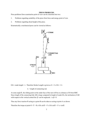
Kinematically a mechanical press can be viewed as follows:
OA= crank length = r. Therefore Stroke Length is given as S = 2 x OA = 2 r
L = length of connecting rod.
At some angle , the sliding point on the under face of the ram will be at a distance of H from BDC.
Since length of the connecting link AB is large compared to length of crank OA, the inclination of AB
with respect to the vertical central line can be neglected. i.e. = 0.
Thus any force reaction R acting at a point B can be taken as acting at point A as shown.
Therefore the torque at point O =T = R x OA sin = F x OA sin = F x r sin
1
2. [F = force exerted by the press which is equal to the resistance experienced by the ram =R]
A press is designed to exert defined amount of force at given crank angle . It means main crankshaft is
designed keeping in view some value of torque. In other words, torque provided by a press is fixed.
T = F * r sin
T
F
r sin
1
F
sin
Where ‘r’ is fixed for a particular operation and dependent on the stroke length.
Therefore force available from press varies with crank angle. F is minimum when 90 and
theoretically infinite when 0 or 180 i.e. at dead ends.
2
3. Though press is capable of exerting infinite force at dead ends, press members such as cranks and
connecting links cannot be designed for infinite load. They have to be designed for finite force. This safe
finite force is to be determined by the dimensions, strength and allowable deflections of press components
such as press frame, connecting link, crank etc. This safe value is known as press capacity and specified
as tonnage at crank angle. Let us say press of 63T at 20 .
Daylight: The maximum clear distance between the two pressing surfaces of a press when surfaces are in
the usable open position. When a bolster plate is supplied it is considered as the pressing surface.
The velocity of ram can be computed using following formula:
N S Sin S
V 0.105 N h ( 1)
60 h
where N = Number of strokes per minute (SPM), h = slide location above ( or before) BDC
S = stroke, = crank angle
Shut height: For a press, the distance from the top of the bed to the bottom of the slide with the stroke
down and adjustment up. In general, it is the maximum die height that can be accommodated for normal
operation, taking the bolster plate into consideration. Shut height is always measured at BDC. There are
two shut heights maximum and minimum
3
4. Position (1) = position corresponding to maximum stroke where Smax= 2 x r1
Position(2) = position corresponding to minimum stroke where Smin = 2 * r2
r1 r2 = (Smax Smin)/2
maximum stroke minimum stroke
Thus, MaxDLH = MinDLH + Press Adjustment +
2
If maximum DLH for a given stroke length, which lies between minimum and maximum stroke length, is
to be found following formulation can be used.
max stroke min stroke
Max DLH stroke = Max DLH
2
DLH STROKE STROKE LENGTH PRESS
POSITION ADJUSTMENT
MAXIMUM TDC MAXIMUM UP
MINIMUM TDC MINIMUM DOWN
ENERGY OVERLOADING: The energy needed for cutting and forming operations during each stroke
is supplied by flywheel which slows down to a permissible percentage, usually 10 20% of its idle speed.
For example, if 10% slow down is permissible
N1
(N0 N1)/N0 = 0.1, which gives 0 .9 .
N0
Total energy of the flywheel
I 2 I * 2 N2
E FT = (constant) * N2 = K N2
2 2 2
60
Where N0 = idle flywheel rpm
N1 = flywheel rpm after stroke
N = flywheel rpm
I = M.I. of the flywheel
= angular velocity
4
5. The total energy supplied (ES) by flywheel includes energy required to overcome friction and elastic
deflections. The electric motor must restore its ideal speed before stroke. The time available between
two strokes depends on type of operation (namely) whether it is continuous or intermittent. In continuous
type of operation, permissible slowdown is 10% and in discontinuous 20%.
I * 2 N1 2
The energy after stroke =
2 60 2
2 2
ES = EFT(N0) EFT(N1) = K N 0 N1
2 2 2
ES K( N 0 N1 ) N1
1
E FT 2 2
K( N 0 ) N0
N1
With a slowdown of 20% = 0.8
N0
ES
1 0.8 2 0.36
E FT
This energy supplied must be more than the required energy.
Shut heights for the press
Shut Height Stroke Position Stroke Press Adjustment
Maximum BDC Maximum UP
Minimum BDC Minimum DOWN
5
6. Problem 1: A press has a maximum DLH (day light height) of 500 mm and a ram adjustment of 60
mm. Calculate maximum and minimum shut height value for a press tooling if the bolster plat
provided on the press bed has a thickness of 80 mm. The press has a variable stoke with maximum
stroke and minimum stroke of150 mm and 10 mm respectively.
Solution
Minimum Shut Height = Maximum DLH Maximum Stroke Press Adjustment
(In case of max DLH, press adjustment is UP but in case of minimum shut height, if is down).
Minimum Shut Height = 500 150 60 = 290 mm
Maximum Shut Height = minimum shut height (SH) + press adjustment +
Max stroke Min stroke
2
(150 10 )
= 290 + 60 + = 420 mm
2
To calculate shut height for a tooling, thickness of bolster plates must be deducted from press shut
heights.
Max SH for die = 420 80 = 340 mm
Min SH for die = 290 80 = 210 mm
6
7. Problem 2: A press has minimum DLH 325 mm and Adjustment of ram is 75 mm. Stroke is
variable and can be varied from 12.5 mm to 100 mm. If the bolster plate provided has a thickness
of 80 mm, calculate maximum and minimum shut height for a die.
Solution
Maximum DLH = minimum DLH + (r1 r2) + P.A. (press adjustment)
100 12 .5
= 325 75 = 443.75 mm
2
Minimum shut height = Max DLH Max Stroke press adjustment = 443.75 100 75
= 268.75 mm
max stroke min stroke
Maximum shut height = minimum shut height + PA +
2
= 268.75 + 75 + 43.75 = 387.5 mm
Max shut height for tooling = 387.5 bolster plate thickness (= 80 mm) = 387.5 80 = 307.5 mm
Min shut height for tooling = 268.75 80 = 188.75 mm
Problem 3: A press has maximum DLH 500 mm and a ram adjustment of 60 mm. Stroke can be varied
from 10 mm to 150 mm. Calculate minimum and maximum shut height for a press tool for stroke of 100
mm and bolster plate thickness of 80 mm.
Solution: First it is necessary to calculate max DLH for stroke length equal to 100 mm as maximum DLH
given (500 mm) corresponds to maximum stroke of 150 mm stroke.
max stroke(r1 ) given stroke(r ) (150 100 )
= MaxDLH = 500 = 475 mm
2 2
Min shut height of press = max DLH stroke PA (since PA is up in case of max DLH but down in
case of min SH)
= 475 100 60 = 315 mm
Max SH of press = Min SH + PA = 315 + 60 = 375 mm
7
8. OR
Max SH of press = Max DLH100 Stroke = 475 100 =375 mm
Min SH of press = Max SH PA = 375 60= 315 mm
Max Shut height for die = Max SH for press bolster plate thickness = 375 80 = 295 mm
Min shut height for die = Min SH for press bolsters plate thickness = 315 80 = 235 mm
Problem 4: A press has minimum of DLH 325 mm and press adjustment of slide of 75 mm. Stroke
can be varied from 12.5 mm to 100 mm. Bolster plate thickness is 75 mm. Calculate permitted
shut height for die if stroke is fixed at 50 mm.
Solution
Given stroke min stroke
Minimum DLH for 50 mm stroke = min DLH (for 12.5 mm stroke) +
2
(50 12 .5)
= 325 = 343.75 mm
2
8
9. Minimum shut height of the press = min DLH (for 50 mm stroke) stroke = 343.75 50 =293.75 mm
Maximum SH of the press = min SH + PA = 293.75 + 75 = 368.75 mm
Maximum SH for the die = max SH for press bolster plate thickness = 368.75 75= 293.75 mm
Minimum SH for the die = min SH for press bolster plate thickness = 293.75 75 = 218.75 mm
Problem 5: A press is designed to offer 90 ton of force at 20 crank angle with a stroke of 15 cm.
Stroke is variable from 1 cm to 15 cm. Calculate tonnage available when ram is 3 cm above its
BDC. Take stroke length equal to 10 cm.
Solution
Given h = 3 cm, s = 10 cm.
h 1 cos
Where = crank angle from BDC
s 2
3 1 Cos
10 2
=> 66 .42
As we know that
s
T = F x r x sin = F* * sin = constant
2
s s
=> T F * 1 * sin 1 = F2 * 2 * sin 2
1
2 2
F1 = force available 90T at crank angle 1 20 and stroke s1 = 15 cm.
F2 = force available at 3 cm above BDC and stroke s2 = 10 cm, 66.42
15 10
90 * * sin(20 ) F2 * * sin(66 .42 )
2 2
=>F2 = 50.4T i.e. tonnage available when ram is 3 cm above the BDC is 50.4T
Problem 6: Check regarding the suitability of the press with following press data for blanking and
drawing operation with combination die.
Capacity of the press tool is 150 T at 20 from BDC
Stroke length=120mm
Total fly wheel energy = 180T cm
Permitted slowdown of speed = 20%
Blanking load = 30T
Drawing force = 10T
Blank holding force = 3T
Depth of cup = 35 mm = 3.5 cm
Stock thickness = 1 mm = 0.1 cm
Percent Penetration = 30%
9
10. Solution:
I. Suitability of press from tonnage point of view:
Total load on the press = blanking load + drawing load + blank holding force = 40 + 10 + 3 = 53 T
Since depth of drawn cup is 3.5 cm, drawing will commence at height of 3.5 cm from BDC assuming
bottom edge of the cup is at BDC. Further, force increases towards the BDC. Now, we will determine
tonnage available at a height of 3.5 cm.
h = 3.5 cm, assuming stroke = 12 cm.
h 1 cos
S 2
3.5 1 cos
gives = 65.37
12 2
Since torque transmitted by crank shaft is constant,
S1 S2
T F1 sin 1 F2 sin 2
2 2
As stroke length is unchanged, S1 S2
F2 sin 2 F1 sin 1
F2 sin (65.4 ) 150 sin (20 )
F2 56 .44 T
Conclusion: As available tonnage F2 is greater than the required tonnage (53T), the given press is
suitable to carry out the given operations from tonnage point of view.
II. Suitability of the press from the energy point of view
Total energy required = Energy for blanking + Energy for drawing + Energy for blank holding
Energy required for blanking = Force x distance = F x K x t = 40 x 0.3 x 0.1 = 1.2T.cm
Energy required for drawing = Force x distance (= cup depth) = 10 x 3.5 = 35 T. cm
Energy for blank holding = Blank holding force x distance (= cup depth) = 3 x 3.5 = 10.5 T.cm
Total energy required = 1.2 + 35 + 10.5 = 46.7 T. cm
10
11. Energy available from the flywheel:
Permitted slowdown of speed = 0.2
N0 N1 N1
0.2 gives 0.8
N0 N0
Energy supplied (ES ) 2
N1
We know that, 1 1 (0.8) 2
Total energy of the flywheel(E FT ) 2
N0
ES
= 0.36
E FT
ES E FT * 0.36 = 64.8 T. cm
Conclusion: Since the energy supplied (64.8 T. cm) is more than energy required (46.7T.cm); the press is
suitable from energy point of view. Thus, the press is suitable from both tonnage and energy point of
view.
Problem 7: Tonnage rating of a given press is 160 T at 20 crank angle from BDC. Stroke is
variable from 10 mm to 120 mm in steps of 10 mm. The ram can be adjusted by 100 mm.
Maximum DLH of the press is 500 mm. Total energy of the flywheel is 180T.cm.Permissible
slowdown in speed is 20%. If it is decided to use stroke of 100 mm, calculate
1. The maximum and minimum shut height for a combination die.
2. Tonnage available at 25 mm from BDC.
3. Check the suitability of press for following operation: Blanking and drawing with the help of
combination die.
Blanking load is 45T. Drawing force is 10T. Blank holding force is 3T. Cup depth is 20 mm.
Stock thickness is 1.5 mm. Percent penetration is 30%.
Solution
(i) Maximum DLH at 120 mm (max stroke) is equal to 500 mm. Therefore, it is necessary to find the
max DLH at 100 mm stroke.
(Max stroke given strok)
Max DLH at 100 mm stroke = max DLH at 120 mm stroke
2
11
12. (120 100)
= 500 = 490mm
2
Maximum SH of the press = Max DLH at 100 m stroke - stroke = 490 100 = 390 mm
Minimum SH of the press = Max SH press adjustment= 390 100 = 290 mm
Since there is no mention of bolster plate, we may assume bolster plate thickness of 60mm.
Maximum shut height of combination die is =390-60= 330mm
Minimum shut height of combination die is =290-60= 230mm
(ii) Suitability of the press from the tonnage point of view
Determining force availability at height of 25 mm from BDC
h= 25 mm = 2.5 cm, S = 100 mm = 10 cm
h 1 cos 2
S 2
2 .5 1 cos 2
10 2
2 60
S1 S2
T F1 sin 1 F2 sin 2
2 2
F1 160 T, 1 20 , S1 12 cm
F2 = ? 2 = 60 , S 2 = 10 cm
Since max tonnage is available at max tonnage
12 10
160 sin (20 ) F2 sin (60 )
2 2
F2 75 .8 T i.e. Force offered by the press at a height of 25 mm from BDC.
Height of the cup is 20 m and total force required for blanking and drawing is 58 T (45 + 10 + 3). As
force at height of 25 mm from BDC is greater than the required, force at 20 mm from BDC must be far
greater than required (58 T). Hence, the given press is suitable to carry out given operations from tonnage
point of view.
12
13. Suitability of the press from the energy point of view
Total energy required = blanking + drawing + blank holding
= (force x K x t 0 ) + (drawing load x depth of cup)+ (Blank holding force * depth
of cup)
= (45 * 0.33 * 0.15) + (10 * 2) + (3 * 2) = 28.23 T. cm
Energy supplied by the flywheel when permitted slowdown is 20%….
N N1
1 0.2 that gives 0.8
N0 N0
Energy supplied (E S ) 2
N1
1 1 (0.8) 2
Total energy of the flywheel(E FT ) 2
N0
ES
0.36
E FT
ES EFT 0.36 = 180 x 0.36 = 64.8 T.cm
Energy supplied by the flywheel (64.8 T.cm) is substantially more than required for the operation (28.23
T.cm). The press is suitable from the energy point of view.
In sum, the given press is suitable to carry out given operations from tonnage as well as energy
point of view.
Problem 8: The punch force required for a cup drawing operation is 10 T. Depth of the cup is 35
mm. An air operated blank holder provides a force of 3 T to prevent wrinkling. A 45 T capacity
press having total flywheel energy = 33 T. cm is available for use. Another press of capacity 150 T
and flywheel energy 180 T. cm is also available. Permissible slowdown of speed is 20%. Calculate
total energy required and select a press.
Solution
Total tonnage required to draw the cup =10+3=13 Ton
Energy required for cup drawing = Force x depth of cup = (10 + 3) x 3.5 = 45.5 T.cm
First press is unsuitable to carry out the operation from energy point of view.
13
14. N1
0.8 From given data
N0
Energy supplied (ES ) 2
N1
1 1 (0.8) 2 =0.36
Total energy of the flywheel(E FT ) 2
N0
Energy Available from the second Press
ES EFT 0.36 = 180 x 0.36 = 64.8 T. cm
The available energy from the second press is more than the energy required for the operation and
therefore this press is suitable for the operation from energy point of view and can be selected.
Problem 9: A press is designed for giving 120 t at 30 crank from BDC, when stroke is 20 cm. Prepare a
monograph from BDC. From the monograph explain:
1. Overloading of torque without overloading capacity.
2. Overloading of capacity without overloading of torque.
Solution: We know that
S
h= r r cos = (1 cos )
2
h (1 cos )
s 2
Torque provided by a press remains constant
14
15. S 2T
T F sin which gives F ………….(1)
2 S sin
In given press T is equal to
20
T 120 sin (30 ) = 600 T. cm
2
2 600 60
F = = …………………………………………(2)
20 sin sin
For equation (1) and (2), common variable is
0 30 45 60 75 90 120 150 180
F 120 85 69 62 60 69 120
h/s 0 0.07 0.15 0.25 0.37 0.5 0.75 0.93 1.0
A graph can be drawn to show up the relationship.
1. Overloading of torque without overloading capacity
Press will get overloaded if load requirement is more than 120 T. Any point above ZZ means overloading
of press and press members will fail. One may select any point on any line like A1 where press will be
under loaded. Any point on curve like A2 will have torque equal to that available on the press i.e.
3
600Tcm. Select any point A at = 60 and load equal to F = 80T which is less than rated capacity of
120 T meaning that it is under loaded.
S 20
T F sin 80 sin (60 )
2 2
= 692.8 T. cm which is greater than available torque (600 T.cm)
Thus, at the point A3 there is overloading of torque without overloading the capacity.
Any point between A 1 to A 2 will not cause overloading of torque and obliviously not causing
overloading.
Take F = 80T, and = 45 ,
S 20
T = F sin 80 sin (45 ) = 565.68 T.cm
2 2
15
16. 2. Overloading of capacity without overloading torque
Take point B where F = 140 T and = 15
Since the load is more than 120 T, the press is overloaded
S 20
T F sin 140 sin (15 ) = 362.34 T. cm (less than 600T cm.)
2 2
This is the case of overloading press capacity (F = 140 T beyond 120 T) without overloading the torque.
16
![[F = force exerted by the press which is equal to the resistance experienced by the ram =R]
A press is designed to exert defined amount of force at given crank angle . It means main crankshaft is
designed keeping in view some value of torque. In other words, torque provided by a press is fixed.
T = F * r sin
T
F
r sin
1
F
sin
Where ‘r’ is fixed for a particular operation and dependent on the stroke length.
Therefore force available from press varies with crank angle. F is minimum when 90 and
theoretically infinite when 0 or 180 i.e. at dead ends.
2](data:image/gif;base64,R0lGODlhAQABAIAAAAAAAP///yH5BAEAAAAALAAAAAABAAEAAAIBRAA7)