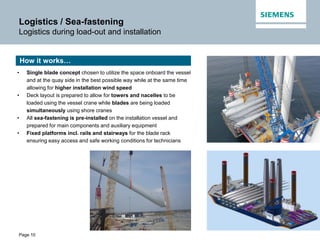
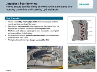
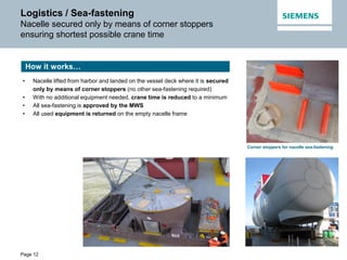
Page 1
Optimized concepts for loading &
installing Offshore wind turbines
Transport & Installation for Offshore Wind | 28-30 April, 2015
Page 2
Table of contents
4
Logistics / Sea-fastening3
Transport Equipment2
Installation Equipment
Introduction1 Introduction1
Page 3
Introduction
Jesper Møller
Senior Key Expert Offshore Installation
• Started in Bonus Energy A/S in 1998
• Lifting Specialist in 2009
• Lifting Expert in 2011
• Senior Key Expert in 2014
Currently heading
− Global Offshore lifting department
− Global competence center for lifting
Page 4
Table of contents
4
Logistics / Sea-fastening3
Transport Equipment2
Installation Equipment
Introduction1
Transport Equipment2
Page 5
Transport equipment
Transport equipment overview 6.0 MW
Page 6
Transport Equipment
Transporting systems increasing safety and
ensuring transport with less component damages
Tower transportTransport nacelle rear end
Transport frame for hub
 All handling / lifting performed without touching the component
 Transport equipment mounted at production facility and used until
pre-assembly / installation
 Transport damages reduced to a minimum
 Cost reductions and increased safety due to reduced number of
lifting operations
 Only one option for lifting the components
 Reduction of heavy lifts for personnel (slings, shackles etc.)
 Tower transportation equipment also used for lifting
What we achieve…
Transport frame for hub
Complete nacelle at the pre-assembly site ready for functional test
 Assembly of nacelle rear end, generator and hub
 Mounting of turner tool
 Functional test of the complete nacelle before it is shipped to site
On the pre-assembly site…
Page 7
Transport Equipment
The art of transporting 75 m blades from
production to site in the safest and most cost-effective way
• All equipment mounted at production site and used during
transport to pre-assembly site
• Main lifting eyes for single point lifting, i.e. lifting operations
performed only in transport equipment without touching the
component
• Friction pads on tip clamp for ensuring optimal fixation of the
blade in correct position and elimination of transport
damages
• Possible to transport blade with stud bolts and blade bearing
cover mounted from production
 Transport damages reduced to a minimum
 Number of handlings reduced
 Reduction of heavy lifts for personnel (slings, shackles etc.)
 Cost reductions and increased safety due to reduced number of
lifting operations
Blade resting in tip clampA Frame mounted on root end
How it works…
What we achieve…
B75 transport
Page 8
Transport Equipment
How to move 75 m blades internally
without compromising flexibility and safety?
• Consists of two parts – root end and tip end mover
• Enables flexible blade transport at production facility / harbor
• Tuck master for root end / tip end remote controlled by technician on
ground = high maneuverability
• Cost reductions and increased safety due to reduced number of
lifting operations
Blade mover for internal transport…
Root end mover Tip end mover
Page 9
Table of contents
4
Logistic/Sea-fastening3
Transport Equipment2
Installation Equipment
Introduction1
Logistics / Sea-fastening3
Page 10
Logistics / Sea-fastening
Logistics during load-out and installation
• Single blade concept chosen to utilize the space onboard the vessel
and at the quay side in the best possible way while at the same time
allowing for higher installation wind speed
• Deck layout is prepared to allow for towers and nacelles to be
loaded using the vessel crane while blades are being loaded
simultaneously using shore cranes
• All sea-fastening is pre-installed on the installation vessel and
prepared for main components and auxiliary equipment
• Fixed platforms incl. rails and stairways for the blade rack
ensuring easy access and safe working conditions for technicians
How it works…
Page 11
Logistics / Sea-fastening
How to ensure safe fastening of towers while at the same time
reducing crane time and speeding up installation
• Towers secured by means of pin bolts which ensures easy and safe
mounting and demounting of the towers
• Everything is pre-mounted and the tower can be lifted directly from the
harbor to the installation ship thereby reducing crane time
• Platforms incl. rails and stairways for easy access also ensuring safe
working conditions for technicians
• Implementation of partly hydraulic sea-fastening solution has reduced
installation time even further
• The hydraulic sea-fastening is design approved by DNV
How it works…
Page 12
Logistics / Sea-fastening
Nacelle secured only by means of corner stoppers
ensuring shortest possible crane time
• Nacelle lifted from harbor and landed on the vessel deck where it is secured
only by means of corner stoppers (no other sea-fastening required)
• With no additional equipment needed, crane time is reduced to a minimum
• All sea-fastening is approved by the MWS
• All used equipment is returned on the empty nacelle frame
How it works…
Corner stoppers for nacelle sea-fastening
Page 13
Logistics / Sea-fastening
Blade rack design reducing lifts and manual handling during
load-out while at the same time easing installation
Tip end sea-fastening
Root end sea-fastening
• Blades positioned slightly offset in blade rack making it possible to
always lift the top blade for installation
• Same interface used for transport and sea-fastening at the blade root
end
• When lifting the blade onto the vessel, blade root end is secured in the
blade rack by means of a pin ensuring no uplift and no sideways
movement
• For installation, root end equipment bolts are loosened, and the blade
can be lifted directly - without demounting sea-fastening
• At the tip end, the blade is secured by means of crossed slings which
can be opened to allow for direct lifting of the blade
• All in all – crane time is reduced to an absolute minimum
How it works…
Page 14
Table of contents
4 Installation Equipment
Logistic/Sea-fastening3
Transport Equipment2
Introduction1
Installation Equipment4
Page 15
Installation Equipment
Traverse system - how to increase safety while
at the same time reducing the overall installation time?
Guide wire
Tack wire
Traverse
Lifting yoke
Offshore tower Offshore Nacelle Offshore Blade
Page 16
Installation Equipment
How to ensure fast and safe
full tower lifts at high wind speeds?
• Gripper is designed for installation at an average wind speed of 14 m/s
• Stairways and platform integrated for safe and easy access
• Reduction of lifting brackets and loose parts improving safety and reducing
heavy lifts for technicians
• Only fiber pads touching the tower flange
• Tower cover remains mounted during lift
• Only mechanically operated - no hydraulics / electrical systems
• Traverse system enabling rotation of tower for alignment on TP, ie. no
manual handling
• Full GL approval – design, production and load test
How it works…
What we achieve…
 Reduction of installation time compared to traditionally bolted lifting
brackets
 No damages to towers due to fiber pads
 Increased safety and improved working
environment for technicians
Page 17
Installation Equipment
How to safely install a 350 t nacelle 110 m above water level
• Designed for installation at average wind speed of 14 m/s
• Trunnion has the same design for all three lifting devices for our main
component lifts: tower, nacelle and yoke
• Integrated stairways for safe and easy access and preparatory work
• Three-point lift ensuring stable positioning of the nacelle
• Remote-controlled horizontal adjustment during lift
• Reduction of lifting brackets and loose parts improving safety and
reducing heavy lifts for technicians
• Full GL approval – design, production and load test
How it works…
What we achieve…
 Reduction of installation time compared to other known solutions
 Increased safety and improved working environment for technicians
 Future-proof – designed for next generation nacelles
Page 18
Installation Equipment
A flexible giant enabling single blade installation
of B75 blades in average wind speed of 14 m/s
• Single blade installation in average wind speed of 14 m/s
• Dedicated sea fastening frame incl. stairways and platform
• Fully automatic - using a remote control, a technician is able to control the fixation of slings
around the blade
• Data collection allowing for documentation of all lifting operations
• Patented design
• Yaw function allowing for blade adjustments in height while maintaining tagline tension
• Active tilt function allowing horizontal adjustment during installation
• Pitch function is build into the yoke
• Full DNV approval – design, production and load test
How it works…
 No working in heights and no manual
handling of slings improving safety and
reducing installation time
 Preparatory work can be performed without
cherry pickers due to integrated stairways and
platform
 Yaw, tilt and pitch functions allowing for
adjustment of the blade during installation
What we achieve…
Janett lifting yoke – 14 m long, 8 m high and heavy
Page 19
Thank you!
Jesper Møller
Senior Key Expert
Offshore Installation
Fiskergade 1
7100 Vejle
Phone: +45 30375310
E-mail:
jml@siemens.com
siemens.com/answers

Siemens: Optimized concepts for loading & installing offshore wind turbines

  • 1.
    Page 1 Optimized conceptsfor loading & installing Offshore wind turbines Transport & Installation for Offshore Wind | 28-30 April, 2015
  • 2.
    Page 2 Table ofcontents 4 Logistics / Sea-fastening3 Transport Equipment2 Installation Equipment Introduction1 Introduction1
  • 3.
    Page 3 Introduction Jesper Møller SeniorKey Expert Offshore Installation • Started in Bonus Energy A/S in 1998 • Lifting Specialist in 2009 • Lifting Expert in 2011 • Senior Key Expert in 2014 Currently heading − Global Offshore lifting department − Global competence center for lifting
  • 4.
    Page 4 Table ofcontents 4 Logistics / Sea-fastening3 Transport Equipment2 Installation Equipment Introduction1 Transport Equipment2
  • 5.
    Page 5 Transport equipment Transportequipment overview 6.0 MW
  • 6.
    Page 6 Transport Equipment Transportingsystems increasing safety and ensuring transport with less component damages Tower transportTransport nacelle rear end Transport frame for hub  All handling / lifting performed without touching the component  Transport equipment mounted at production facility and used until pre-assembly / installation  Transport damages reduced to a minimum  Cost reductions and increased safety due to reduced number of lifting operations  Only one option for lifting the components  Reduction of heavy lifts for personnel (slings, shackles etc.)  Tower transportation equipment also used for lifting What we achieve… Transport frame for hub Complete nacelle at the pre-assembly site ready for functional test  Assembly of nacelle rear end, generator and hub  Mounting of turner tool  Functional test of the complete nacelle before it is shipped to site On the pre-assembly site…
  • 7.
    Page 7 Transport Equipment Theart of transporting 75 m blades from production to site in the safest and most cost-effective way • All equipment mounted at production site and used during transport to pre-assembly site • Main lifting eyes for single point lifting, i.e. lifting operations performed only in transport equipment without touching the component • Friction pads on tip clamp for ensuring optimal fixation of the blade in correct position and elimination of transport damages • Possible to transport blade with stud bolts and blade bearing cover mounted from production  Transport damages reduced to a minimum  Number of handlings reduced  Reduction of heavy lifts for personnel (slings, shackles etc.)  Cost reductions and increased safety due to reduced number of lifting operations Blade resting in tip clampA Frame mounted on root end How it works… What we achieve… B75 transport
  • 8.
    Page 8 Transport Equipment Howto move 75 m blades internally without compromising flexibility and safety? • Consists of two parts – root end and tip end mover • Enables flexible blade transport at production facility / harbor • Tuck master for root end / tip end remote controlled by technician on ground = high maneuverability • Cost reductions and increased safety due to reduced number of lifting operations Blade mover for internal transport… Root end mover Tip end mover
  • 9.
    Page 9 Table ofcontents 4 Logistic/Sea-fastening3 Transport Equipment2 Installation Equipment Introduction1 Logistics / Sea-fastening3
  • 10.
    Page 10 Logistics /Sea-fastening Logistics during load-out and installation • Single blade concept chosen to utilize the space onboard the vessel and at the quay side in the best possible way while at the same time allowing for higher installation wind speed • Deck layout is prepared to allow for towers and nacelles to be loaded using the vessel crane while blades are being loaded simultaneously using shore cranes • All sea-fastening is pre-installed on the installation vessel and prepared for main components and auxiliary equipment • Fixed platforms incl. rails and stairways for the blade rack ensuring easy access and safe working conditions for technicians How it works…
  • 11.
    Page 11 Logistics /Sea-fastening How to ensure safe fastening of towers while at the same time reducing crane time and speeding up installation • Towers secured by means of pin bolts which ensures easy and safe mounting and demounting of the towers • Everything is pre-mounted and the tower can be lifted directly from the harbor to the installation ship thereby reducing crane time • Platforms incl. rails and stairways for easy access also ensuring safe working conditions for technicians • Implementation of partly hydraulic sea-fastening solution has reduced installation time even further • The hydraulic sea-fastening is design approved by DNV How it works…
  • 12.
    Page 12 Logistics /Sea-fastening Nacelle secured only by means of corner stoppers ensuring shortest possible crane time • Nacelle lifted from harbor and landed on the vessel deck where it is secured only by means of corner stoppers (no other sea-fastening required) • With no additional equipment needed, crane time is reduced to a minimum • All sea-fastening is approved by the MWS • All used equipment is returned on the empty nacelle frame How it works… Corner stoppers for nacelle sea-fastening
  • 13.
    Page 13 Logistics /Sea-fastening Blade rack design reducing lifts and manual handling during load-out while at the same time easing installation Tip end sea-fastening Root end sea-fastening • Blades positioned slightly offset in blade rack making it possible to always lift the top blade for installation • Same interface used for transport and sea-fastening at the blade root end • When lifting the blade onto the vessel, blade root end is secured in the blade rack by means of a pin ensuring no uplift and no sideways movement • For installation, root end equipment bolts are loosened, and the blade can be lifted directly - without demounting sea-fastening • At the tip end, the blade is secured by means of crossed slings which can be opened to allow for direct lifting of the blade • All in all – crane time is reduced to an absolute minimum How it works…
  • 14.
    Page 14 Table ofcontents 4 Installation Equipment Logistic/Sea-fastening3 Transport Equipment2 Introduction1 Installation Equipment4
  • 15.
    Page 15 Installation Equipment Traversesystem - how to increase safety while at the same time reducing the overall installation time? Guide wire Tack wire Traverse Lifting yoke Offshore tower Offshore Nacelle Offshore Blade
  • 16.
    Page 16 Installation Equipment Howto ensure fast and safe full tower lifts at high wind speeds? • Gripper is designed for installation at an average wind speed of 14 m/s • Stairways and platform integrated for safe and easy access • Reduction of lifting brackets and loose parts improving safety and reducing heavy lifts for technicians • Only fiber pads touching the tower flange • Tower cover remains mounted during lift • Only mechanically operated - no hydraulics / electrical systems • Traverse system enabling rotation of tower for alignment on TP, ie. no manual handling • Full GL approval – design, production and load test How it works… What we achieve…  Reduction of installation time compared to traditionally bolted lifting brackets  No damages to towers due to fiber pads  Increased safety and improved working environment for technicians
  • 17.
    Page 17 Installation Equipment Howto safely install a 350 t nacelle 110 m above water level • Designed for installation at average wind speed of 14 m/s • Trunnion has the same design for all three lifting devices for our main component lifts: tower, nacelle and yoke • Integrated stairways for safe and easy access and preparatory work • Three-point lift ensuring stable positioning of the nacelle • Remote-controlled horizontal adjustment during lift • Reduction of lifting brackets and loose parts improving safety and reducing heavy lifts for technicians • Full GL approval – design, production and load test How it works… What we achieve…  Reduction of installation time compared to other known solutions  Increased safety and improved working environment for technicians  Future-proof – designed for next generation nacelles
  • 18.
    Page 18 Installation Equipment Aflexible giant enabling single blade installation of B75 blades in average wind speed of 14 m/s • Single blade installation in average wind speed of 14 m/s • Dedicated sea fastening frame incl. stairways and platform • Fully automatic - using a remote control, a technician is able to control the fixation of slings around the blade • Data collection allowing for documentation of all lifting operations • Patented design • Yaw function allowing for blade adjustments in height while maintaining tagline tension • Active tilt function allowing horizontal adjustment during installation • Pitch function is build into the yoke • Full DNV approval – design, production and load test How it works…  No working in heights and no manual handling of slings improving safety and reducing installation time  Preparatory work can be performed without cherry pickers due to integrated stairways and platform  Yaw, tilt and pitch functions allowing for adjustment of the blade during installation What we achieve… Janett lifting yoke – 14 m long, 8 m high and heavy
  • 19.
    Page 19 Thank you! JesperMøller Senior Key Expert Offshore Installation Fiskergade 1 7100 Vejle Phone: +45 30375310 E-mail: jml@siemens.com siemens.com/answers