A two-wheeler is statically unstable but as the speed increases vehicle achieves stability. At low speed, the vehicle loses its stability. In order to achieve stability, the driver has to balance the vehicle. While negotiating a curve, a vehicle has to lean to a certain angle, if this angle exceeds the certain value, the vehicle tends to skid. In this paper the stability control system is incorporated, so that a vehicle will maintain stability even at low speeds. The stability of a two-wheeler depends on weight distribution, tyre dynamics, speed and steering angle. In this paper, only two parameters are considered, one is steering effect and another one is speed. For developing a simplified model, the speed of the vehicle is kept as constant, using which the effect of steering angle is analysed and accordingly a controller is incorporated for providing stability.
Standard vs Custom Battery Packs - Decoding the Power Play
Stability Control System for a Two-Wheeler
1. IOSR Journal of Electrical and Electronics Engineering (IOSR-JEEE)
e-ISSN: 2278-1676,p-ISSN: 2320-3331, Volume 12, Issue 2 Ver. I (Mar. – Apr. 2017), PP 41-46
www.iosrjournals.org
DOI: 10.9790/1676-1202014146 www.iosrjournals.org 41 | Page
Stability Control System for a Two-Wheeler
1
Niveditha. K, Final year student, 2
Nitta Rani. S, Final year student,
3
Nivedha. S, Final year student, 4
Prof. AL. Kumarappan, Head of the
Department,
1,2,3,4
Department of Electrical and Electronics Engineering, Sri Sairam Engineering College
Abstract: A two-wheeler is statically unstable but as the speed increases vehicle achieves stability. At low
speed, the vehicle loses its stability. In order to achieve stability, the driver has to balance the vehicle. While
negotiating a curve, a vehicle has to lean to a certain angle, if this angle exceeds the certain value, the vehicle
tends to skid. In this paper the stability control system is incorporated, so that a vehicle will maintain stability
even at low speeds. The stability of a two-wheeler depends on weight distribution, tyre dynamics, speed and
steering angle. In this paper, only two parameters are considered, one is steering effect and another one is
speed. For developing a simplified model, the speed of the vehicle is kept as constant, using which the effect of
steering angle is analysed and accordingly a controller is incorporated for providing stability.
Keywords: Motorcycle dynamics, stability, steering torque, controller.
I. Introduction
The stabilization of two-wheeler is analysed from the perspective of control. The two wheelers are
statically unstable like the inverted pendulum, but can be stable when the speed increases. The evolution of two-
wheeler over time has been a product of requisite, inventiveness, materials and industrialisation. To ride a two-
wheeler, a person must have some adequate skills to make the vehicle move in a desired trajectory without
skidding. Once mastered the skill becomes subconscious. Successful control and manoeuvring of a two-wheeler
depend critically on the forces between the wheels and the ground. Acceleration and braking require
longitudinal forces, whereas balancing and turning depends on lateral forces. A good understanding of these
forces is necessary to make appropriate assumptions about valid models of the rolling conditions. The two-
wheeler is assumed to have four rigid parts, specifically, two wheels, a frame, and a front fork with handlebars.
To include the rider in the analysis, the rider’s upper body is modelled as a point mass that can move laterally
with respect to the frame. The rider can apply a torque to the handlebars in-order to vary the steering angle.
While encountering right or left turn, the rider has to control the two-wheeler by leaning and by applying a
torque to the handle bars, henceforth the tilt angle of the vehicle is varied. The main objective of this paper is to
determine the parameters that influence the stability and to provide a system which stabilizes the vehicle. In
order to overcome the problems of the two-wheeler's stability and steering, a set of differential equations has
been derived which was found to be unstable using Bode plot. To make this system stable a feedback loop has
been provided which was derived from the static torque balance equation. The output of the frame with the
feedback system was found to be stable but the system takes more time to settle due to which a controller has
been incorporated in the system with unity feedback.
II. Governing Equation
The simple second order model is framed based on the assumption that the rider has fixed position and
orientation related to frame and that the forward velocity at the rear wheel V is constant. We assume that steer
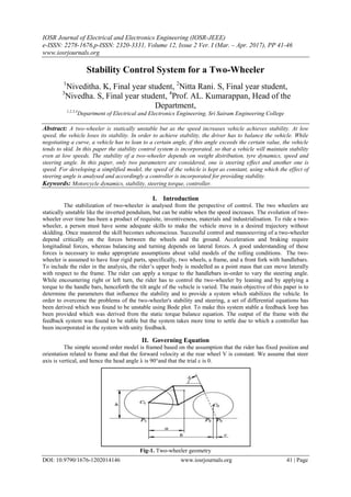
axis is vertical, and hence the head angle λ is 90°and that the trial c is 0.
Fig-1. Two-wheeler geometry
2. Stability Control System for a Two-Wheeler
DOI: 10.9790/1676-1202014146 www.iosrjournals.org 42 | Page
Fig-2. Top view and back view of the two-wheeler
Let m be the total mass of the system,
J be the inertia of the body with respect to x-axis and
D=-Jxz which denotes the inertia product with respect to XZ axis.
The angular momentum of the system with respect to x-axis is,
𝐿 𝑥 =
𝑑𝜑
𝑑𝑡
− 𝐷𝜔 = 𝐽
𝑑𝜑
𝑑𝑡
−
𝑉
𝐷
𝛿
(1)
The torque acting on the system due to gravity and centrifugal forces and angular momentum becomes,
𝐽
𝑑2
𝜑
𝑑𝑡2
− 𝑚𝑔 𝜑 =
𝐷𝑉
𝑏
𝑑𝛿
𝑑𝑡
+
𝑚𝑉2
𝑏
𝛿
(2)
Approximately, the moment of inertia as 𝐽 = 𝑚 2
and the inertia product as = 𝑚𝑎 , the model becomes,
𝑑2
𝜑
𝑑𝑡2
−
𝑔
𝜑 =
𝑎𝑣
𝑏
𝑑𝛿
𝑑𝑡
+
𝑉2
𝑏
𝛿
(3)
Therefore,
The poles are
𝑝1,2 = ±
𝑚𝑔
𝐽
≈ ±
𝑔
(4a)
And the zeros are
𝑍 = −
𝑚𝑣
𝐷
≈ −
𝑉
𝑎
(4b)
Thus, the transfer function from steer angle δ to tilt angle Ψ is
𝐺 𝜑𝛿 𝑠 =
𝑉(𝐷𝑠 + 𝑚𝑣 )
𝑏(𝐽𝑠2 − 𝑚𝑔 )
(5)
𝐺 𝜑𝛿 𝑠 =
𝑉𝐷
𝑏𝐽
𝑠 +
𝑚𝑣
𝐷
𝑠2 −
𝑚𝑔
𝐽
≈
𝑎𝑣
𝑏
𝑠 +
𝑉
𝑎
𝑠2 −
𝑔
(6)
Here both the gain and the zero of the transfer function depends on velocity v. The above system is unstable.
Hence it is stabilised by active control using proportional feedback law.
𝛿 = −𝑘2 𝜑 (7)
Which is a closed loop system.
𝐽
𝑑2
𝜑
𝑑𝑡2
+
𝐷𝑉𝑘2
𝑏
𝑑𝜑
𝑑𝑡
+
𝑚𝑉2
𝑘2
𝑏
− 𝑚𝑔 𝜑 = 0
(8)
3. Stability Control System for a Two-Wheeler
DOI: 10.9790/1676-1202014146 www.iosrjournals.org 43 | Page
Table I. Parameters with their values that was used for the simulation
Vehicle parameters Value Unit
m 200,250 kg
b 1,1.5 m
a 0.4 m
h 0.6 m
c 0.03 m
λ 70 degree
g 9.81 m/s2
V 5,7,10 m/s
To model the front fork, we observe that the steer angle also influences the tilt angle.
The front fork roll angle is given by,
𝜑 𝑓 = 𝜑 − 𝛿 𝑐𝑜𝑠𝜆 (9)
The effective front fork angle is given by
𝛿𝑓 = 𝛿 𝑠𝑖𝑛𝜆 (10)
Let Nf and Ff be the vertical and horizontal components of the forces acting on the front wheel at the ground
contact. Neglecting dynamics and gyroscopic effect we get,
𝑁𝑓 =
𝑎𝑚𝑔
𝑏
(11)
And
𝐹𝑓 =
𝑎𝑚𝑉2
𝑏2
𝛿𝑓 =
𝑎𝑚𝑉2
𝑠𝑖𝑛𝜆
𝑏2
𝛿
(12)
Let T, be the external torque applied to the handle bar, the static torque balance of the front fork becomes,
𝑇 − 𝐹𝑓 + 𝑁𝑓 𝜑 𝑓 𝑐 sin 𝜆 = 0 (13)
𝑇 −
𝑎𝑐𝑚𝑔 sin 𝜆
𝑏
𝜑 −
𝑎𝑐𝑚 sin 𝜆
𝑏2
𝑉2
sin 𝜆 − 𝑏𝑔 cos 𝜆 𝛿 = 0
(14)
If 𝑉 > 𝑉𝑠𝑎 , then the sign of the term proportional to δ is negative.
Where,
𝑉𝑠𝑎 = 𝑏𝑔 cot 𝜆 (15)
The torque balance is written as,
𝛿 = 𝑘1 𝑣 𝑇 − 𝑘2(𝑣)𝜑 (16)
Where,
𝑘1 𝑣 =
𝑏2
𝑉2 sin 𝜆 − 𝑏𝑔 cos 𝜆 𝑚𝑎𝑐 sin 𝜆
(17)
𝑘2 𝑣 =
𝑏𝑔
𝑉2 sin 𝜆 − 𝑏𝑔 cos 𝜆
(18)
III. Simulation Results
MATLAB is the most intended software used for mathematical modelling. MATLAB is the
abbreviation of matrix laboratory. It is a multi-paradigm numerical computing environment and fourth
generation programming language. Although MATLAB indented primarily for numerical computing, an
optional toolbox allows access to symbolic computing capabilities. An additional package, Simulink, adds
graphical simulation and Model Based Design for dynamic and embedded systems.
The vehicle parameters were loaded in the MATLAB and the simulation was started. The simulation
was carried out for the open loop system. The frequency domain analysis using bode plot was done to the open
loop system. The generated results show that the open loop system is unstable.
4. Stability Control System for a Two-Wheeler
DOI: 10.9790/1676-1202014146 www.iosrjournals.org 44 | Page
Fig-3. Bode Plot of the open loop system for V=7m/s
Since the open loop system modelled was found to be unstable a closed loop was designed using the
static torque balance equation. The simulation was carried out for the closed loop system and the output plot was
generated for different magnitude of velocity.
Fig-4. Graph of the feedback system for different velocities
From the graph, it is evident that, for higher velocities the system has more oscillations and the system
takes more time to settle. The response of the system for different wheelbases was plotted for the constant
velocity V=10m/s and is depicted in the graph.
Fig-5. Graph of the feedback system for different wheelbases
The above graph, Fig-5 shows the response of the system for various wheelbases. Increase in
wheelbase of the vehicle, increases the peak overshoot of the response. The response of the system for different
masses was plotted for the constant velocity V=10m/s.
5. Stability Control System for a Two-Wheeler
DOI: 10.9790/1676-1202014146 www.iosrjournals.org 45 | Page
Fig-6. Graph of the feedback system for different mass
The above graph, Fig-6 shows the response of the system for various mass. For the vehicle with greater
mass, the peak overshoot of the system has been decreased but both the system experiences similar oscillatory
response.
IV. Proposed System
Consider a two-wheeler, negotiating a curve. The input to the vehicle is given by the rider in the form
of torque, which is applied to the handle-bar of the vehicle. The steering torque influences the steering angle
which in-turn influence the tilt angle of the system. The system can be stabilized by active steering control.
The tilt angle of the system can be sensed by the accelerometer sensor and rate gyro sensors. The
steering torque is sensed using a torque sensor and the vehicle speed is sensed using a speed sensor. Using the
outputs of the sensor, the steering angle required to vary the tilt angle is obtained. Using the calculated steering
angle, the steering torque required is calculated and it is fed to a PID controller. The PID controller stabilizes the
system as well as reduces the oscillatory response of the system. The output of the PID is given to the stepper
motor which is fitted with the handle-bar of the vehicle.
The Simulink model of the system with the PID controller was modelled and the controller was tuned
using Simulink PID tuner and it was simulated This facilitates easy comparison of the vehicle behaviour with
and without the controller.
V. Results And Discussion
The results of the closed loop system with controller has been multi-plotted with the results of closed
loop system without controller. The comparison of the system response with and without a controller has been
shown in fig-7
Fig-7. Graph of the feedback system with and without controller with a constant step change for V=10m/s
From the fig-7, it is evident that the response of the system with controller follows the desired trajectory
whereas the system without a controller oscillates and takes more time to settle.
6. Stability Control System for a Two-Wheeler
DOI: 10.9790/1676-1202014146 www.iosrjournals.org 46 | Page
Fig-8. Graph of the feedback system with and without controller with variable step change for V=10m/s
It can be thus proved by simulation that the stability system for a two-wheeler has been successfully modelled,
simulated and evaluated. The system can be implemented after modifying the front fork of the chassis.
Acknowledgement
We would like to thank for the helpful advice received from Professor Dr.S.Vaidyanathan, Department
of Mechanical Engineering and Professor Dr.K.Renganathan, Head of the Department, Department of
Electronics and Instrumentation Engineering of Sri Sairam Engineering College.
References
[1]. Mukeshkumar Prasad 1, Nilesh W. Nirwan, “Design and Fabrication of Automatic Balancing Bicycle”, International Journal of
Science, Engineering and Technology Research (IJSETR), Volume 5, Issue 2, February 2016
[2]. Ashik-E-Rasul, Nowab Md. Aminul Haq, “Stabilizing and Balancing of Linear and Rotary Inverted Pendulum System”, Bangladesh
University of Engineering and Technology (BUET) Dhaka-1000, Bangladesh February, 2016
[3]. H. Goldstein, Classical Mechanics. Addison-Wesley, Cambridge, MA, 1953. p. 145
[4]. J. Lowell and H. D. McKell. “The stability of bicycles.” Am. J. Phys. 50:12, pp. 1106–1112, 1982
[5]. M. Ghosh, S. Mukhopadhyay, “Stability Analysis of a Two-wheeler during Curve Negotiation under Braking”, 14th National
Conference on Machines and Mechanisms (NaCoMM09)
[6]. S. Timoshenko and D. H. Young, Advanced Dynamics. McGraw Hill, New York, 1948. page 239
[7]. Vipul Gupta, “Self-balancing bot”, summer project as a part electronics lab, IIT Kanpur.