

Recommended
Recommended
More Related Content
What's hot
What's hot (20)
Viewers also liked
Viewers also liked (17)
Similar to H010244147
Similar to H010244147 (20)
More from IOSR Journals
Recently uploaded
Recently uploaded (20)
H010244147
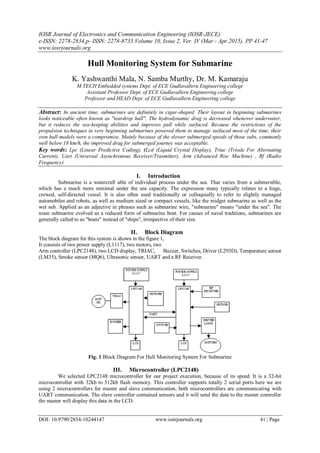
- 1. IOSR Journal of Electronics and Communication Engineering (IOSR-JECE) e-ISSN: 2278-2834,p- ISSN: 2278-8735.Volume 10, Issue 2, Ver. IV (Mar - Apr.2015), PP 41-47 www.iosrjournals.org DOI: 10.9790/2834-10244147 www.iosrjournals.org 41 | Page Hull Monitoring System for Submarine K. Yashwanthi Mala, N. Samba Murthy, Dr. M. Kamaraju M.TECH Embedded systems Dept. of ECE Gudlavalleru Engineering college Assistant Professor Dept. of ECE Gudlavalleru Engineering college Professor and HEAD Dept .of ECE Gudlavalleru Engineering college Abstract: In ancient time, submarines are definitely in cigar-shaped. Their layout in beginning submarines looks noticeable often known as "teardrop hull". The hydrodynamic drag is decreased whenever underwater, but it reduces the sea-keeping abilities and improves pull while surfaced. Because the restrictions of the propulsion techniques in very beginning submarines powered them to manage surfaced most of the time, their own hull models were a compromise. Mainly because of the slower submerged speeds of those subs, commonly well below 18 km/h, the improved drag for submerged journey was acceptable. Key words: Lpc (Linear Predictive Coding), (Lcd (Liquid Crystal Display), Triac (Triode For Alternating Current), Uart (Universal Asynchronous Receiver/Trasmitter), Arm (Advanced Risc Machine) , Rf (Radio Frequency) I. Introduction Submarine is a watercraft able of individual process under the sea. That varies from a submersible, which has a much more minimal under the sea capacity. The expression many typically relates to a huge, crewed, self-directed vessel. It is also often used traditionally or colloquially to refer to slightly managed automobiles and robots, as well as medium sized or compact vessels, like the midget submarine as well as the wet sub. Applied as an adjective in phrases such as submarine wire, "submarine" means "under the sea". The noun submarine evolved as a reduced form of submarine boat. For causes of naval traditions, submarines are generally called to as "boats" instead of "ships", irrespective of their size. II. Block Diagram The block diagram for this system is shown in the figure 1, It consists of two power supply (L1117), two motors, two Arm controller (LPC2148), two LCD display, TRIAC, Buzzer, Switches, Driver (L293D), Temperature sensor (LM35), Smoke sensor (MQ6), Ultrasonic sensor, UART and a RF Receiver. Fig. 1 Block Diagram For Hull Monitoring System For Submarine III. Microcontroller (LPC2148) We selected LPC2148 microcontroller for our project execution, because of its speed. It is a 32-bit microcontroller with 32kb to 512kb flash memory. This controller supports totally 2 serial ports here we are using 2 microcontrollers for master and slave communication, both microcontrollers are communicating with UART communication. The slave controller contained sensors and it will send the data to the master controller the master will display this data in the LCD.
- 2. Hull Monitoring System for Submarine DOI: 10.9790/2834-10244147 www.iosrjournals.org 42 | Page The slave section operates motor and buzzer and master drives the hull motors .the master will take different decisions related to the hull, by collecting data from the keypad and RF receiver. IV. Gas/Smoke Detector (MQ 6) A smoke detector is a device which detects the presence of smoke within an area, usually as part of a safety system. This type of equipment is used to detect a smoke leak and interface with a control system so a process can be automatically shut down. A smoke detector can also sound an alarm to operators in the area where the leak is occurring, giving them the opportunity to leave the area. This type of device is important because there are many type of smokes that can be harmful to organic life, such as humans or animals. Fig.2 Smoke/Gas Detector (MQ6) V. Tererature Detector (LM35) The LM35 series are precision integrated-circuit temperature sensors, whose output voltage is linearly proportional to the Celsius (Centigrade) temperature. The LM35 thus has an advantage over linear temperature sensors calibrated in ° Kelvin, as the user is not required to subtract a large constant voltage from its output to obtain convenient Centigrade scaling. The LM35 does not require any external calibration or trimming to provide typical accuracies of ±1⁄4°C at room temperature and ±3⁄4°C over a full −55 to +150°C temperature range. Fig.3 Temperature Detector (LM35) VI. Principle Of The Ultrasonic Detector Ultrasonic sensors emit short, high-frequency sound pulses at regular intervals. These propagate in the air at the velocity of sound. If they strike an object, then they are reflected back as echo signals to the sensor, which itself computes the distance to the target based on the time-span between emitting the signal and receiving the echo.
- 3. Hull Monitoring System for Submarine DOI: 10.9790/2834-10244147 www.iosrjournals.org 43 | Page Fig. 4 Detection Of Ultrasonic Sensor Virtually all materials which reflect sound can be detected, regardless of their colour. Even transparent materials or thin foils represent no problem for ultrasonic sensor. Micro sonic ultrasonic sensors are suitable for target distances from 20 mm to 10 m and as they measure the time of flight they can ascertain a measurement with pinpoint accuracy. Some of our sensors can even resolve the signal to an accuracy of 0.025 mm. Ultrasonic sensors can see through dust-laden air and ink mists. Even thin deposits on the sensor membrane do not impair its function. Sensors with a blind zone of only 20 mm and an extremely thin beam spread are making entirely new applications possible today: Fill level measurement in wells of micro titer plates and test tubes, as well as the detection of small bottles in the packaging industry, can be implemented with ease. Even thin wires are reliably detected. VII. About RF 1) The STT-433 is ideal for remote control applications where low cost and longer range is required. 2) The transmitter operates from 1.5-12V supply, making it ideal for battery-powered applications. 3) The transmitter employs a SAW-stabilized oscillator, ensuring accurate frequency control for best range performance. 4) The manufacturing-friendly SIP style package and low-cost make the STT-433 suitable for high volume applications. VIII. Features 1) 433.92 MHz Frequency 2) Low Cost 3) 1.5-12V operation 4) Small size Fig. 5 Internal Diagram For Rf Trasmitter And Receiver IX ALGORITHM: 1) Slave Side 1. Start the project 2. Check the temperature 3. Send the temperature to the master, display the value in LCD then switch on the buzzer and motor 4. Check the smoke
- 4. Hull Monitoring System for Submarine DOI: 10.9790/2834-10244147 www.iosrjournals.org 44 | Page 5. Send the smoke to the master, display the value in LCD then switch on the buzzer and motor. 6. If any command from master switch on the motor and Buzzer. 7. Go to step1. 2). Master side: 1. Receive the temperature and smoke from slave and to display these values in LCD. 2. Check the obstacle 3. If obstacle is there stop the boat. 4. Check the command from RF. 5. If any command from RF stop the motors. 6. If buzzer or water pump off command is received send the data to the slave. 7. Check the switch status, 8. If switch is pressed stop the motors. 9. Go to step 1. IX. Circuit Diagram The internal circuit diagram for hull monitoring system for submarine is shown in the figure6 and figure7, The diagram shown in the figure 6 represents the operation of slave side and diagram in the figure7 represent the operation of master side. GND ISP 3.3v P1.22 C8 CAP LS2 BUZZER 1 2 p0.11 p0.10 MOC3010 1 2 64 XTAL1 GND U4 MAX232 1 3 4 5 1615 2 6 12 9 11 10 13 8 14 7 C1+ C1- C2+ C2- VCCGND V+ V- R1OUT R2OUT T1IN T2IN R1IN R2IN T1OUT T2OUT 3.3V r2in 10K P0.12 U2 7805 1 3 2 VIN VOUT GND p1.18 +5v - + D1 BRIDGE 1 4 3 2 out1 r2in 3.3V MOTOR AC 1 2 10k VCC ISP SW BT 136 3.3V V2 C6 CAP P0.13 GND VCC+5v VCC_BAR GND D2 LED U4 3.3V 1 3 2 VIN VOUT GND P0.10 RST LPC2148 19 21 22 26 27 29 30 31 33 34 35 37 38 39 41 45 46 47 53 54 55 1 2 58 57 9 10 11 13 14 15 17 51 43 23 50 42 25 18 6 49 63 7 59 5 3 61 62 36 40 44 48 4 8 12 16 20 52 56 60 64 24 28 32 P0.0 P0.1 P0.2 P0.3 P0.4 P0.5 P0.6 P0.7 P0.8 P0.9 P0.10 P0.11 P0.12 P0.13 P0.14 P0.15 P0.16 P0.17 PO.18 P0.19 P0.20 P0.21 P0.22 P0.23 RESET P0.25 D+ D- P0.28 P0.29 P0.30 P0.31 VDD VDD VDD VSS VSS VSS VSS VSS VBAT VREF VDDA VSSA RTXC2 RTXC1 XTAL2 XTAL1 P1.23 P1.22 P1.21 P1.20 P1.19 P1.18 P1.17 P1.16 P1.31 P1.30 P1.29 P1.28 P1.27 P1.26 P1.25 P1.24 out2 +5v P1.22 XTAL2 C5 CAP +5v r2out P0.11 3.3v MQ6 P1.24 1k GND 3.3v GND C7 CAP P1.24 3.3v 10k Y1 12MHZ t2out GND t2out 0.1UF V1 220v Ac LM35 C1 1000uf com VCC R1 330E p0.13 p1.19 J26 LCD 1 2 3 4 5 6 7 8 9 10 11 12 13 14 15 16 T1 1 5 4 8 SLAVE SIDE p1.17 GND p0.12 IP2 3.3v GND t2in Fig. 5 Internal Operation Of Slave Side
- 5. Hull Monitoring System for Submarine DOI: 10.9790/2834-10244147 www.iosrjournals.org 45 | Page P0.11 3.3V 10k U4 HT12D 14 17 18 1 2 3 4 5 6 7 8 16 15 10 11 12 13 DIN VT VDD A0 A1 A2 A3 A4 A5 A6 A7 OSC1 OSC2 D8 D9 D10 D11 GND P1.24 D2 LED P1.24 VCC RX +5v MASTER SIDE P0.10 P1.22 C7 CAP P1.22 XTAL2 p1.20 T1 1 5 4 8 GND10K +5v ISP SW Y1 12MHZ stop sw MG4 12 p0.17 p0.11 p0.14 3.3v 3.3V E1 ANTENNA VCC p0.15 +5v p1.18 P0.13 GND 1k t2out rf receiver +5v U4 3.3V 1 3 2 VIN VOUT GND R1 330E VCC U2 7805 1 3 2 VIN VOUT GND TX p1.19 GND MG1 12 R3 R VCC +5v LPC2148 19 21 22 26 27 29 30 31 33 34 35 37 38 39 41 45 46 47 53 54 55 1 2 58 57 9 10 11 13 14 15 17 51 43 23 50 42 25 18 6 49 63 7 59 5 3 61 62 36 40 44 48 4 8 12 16 20 52 56 60 64 24 28 32 P0.0 P0.1 P0.2 P0.3 P0.4 P0.5 P0.6 P0.7 P0.8 P0.9 P0.10 P0.11 P0.12 P0.13 P0.14 P0.15 P0.16 P0.17 PO.18 P0.19 P0.20 P0.21 P0.22 P0.23 RESET P0.25 D+ D- P0.28 P0.29 P0.30 P0.31 VDD VDD VDD VSS VSS VSS VSS VSS VBAT VREF VDDA VSSA RTXC2 RTXC1 XTAL2 XTAL1 P1.23 P1.22 P1.21 P1.20 P1.19 P1.18 P1.17 P1.16 P1.31 P1.30 P1.29 P1.28 P1.27 P1.26 P1.25 P1.24 p1.17 p0.13 p0.21 U4 MAX232 1 3 4 5 1615 2 6 12 9 11 10 13 8 14 7 C1+ C1- C2+ C2- VCCGND V+ V- R1OUT R2OUT T1IN T2IN R1IN R2IN T1OUT T2OUT V2 +5v C6 CAP IP2 0.1UF ISP VCC r2in U5 L293D 2 7 10 15 1 9 3 6 11 14 16 8 IN1 IN2 IN3 IN4 EN1 EN2 OUT1 OUT2 OUT3 OUT4 VSS VS 10k 3.3V XTAL1 r2out t2in com p0.12 VCC t2out - + D1 BRIDGE 1 4 3 2 GND C1 1000uf J26 LCD 1 2 3 4 5 6 7 8 9 10 11 12 13 14 15 16 GND r2in C5 CAP GND p1.21 GND +3.3v C8 CAP p0.10 p0.20 p0.16 P0.12 3.3V RST GND MG2 12 MG2 12 Fig. 6 Internal Operation Of Master Side X. Outputs The outputs pictures related to hull monitoring system for submarine is Shown in the below figures, Fig.7 The Kit For Hull Monitoring System For Submarine
- 6. Hull Monitoring System for Submarine DOI: 10.9790/2834-10244147 www.iosrjournals.org 46 | Page Fig.8 Working Of The Kit When We Supply The Power Fig.9 The System Detected Smoke And Temperature Readings Displayed On The Lcd Display XI. Conclusion The mechanism is cheap and flexible for testing submarine by using alarm and monitoring control. This control setup use for submarines which has both digital and analog circuit boards interface. The proposed designed control system control several types of self-running process control station, each type is dictated to certain task. The alarm system is connected to sensors all over the place in the submarine and always monitors them, if any sensor reading is outside the preset limits we get an alarm. The observing setup can capture any alarm condition and store it in hard disk or printer with timestamp. Including to that it will be applied as basic to test variety of all ship condition from the link. They require to shorten manning stage led to the improvement of automated controls essential schemes for the engine room plant which allowed unattended operation of devices spaces. With vessels capable of safe functioning for any stage of time in this mode, all the handling functions and following features are gathered combined in a system controls Room for sample. The system take small energy in arrange of only a few mill amperes per interface and drivers is safeguarded like that it frequently holds the consumer from harmful sensor that was in place or developed inappropriately. This system feature increases the setup and decreases the slide down time. The direct development layout interface enables the multiple use of the design in a variety of cases specifically when putting in or improving sensor or method in the submarine. Engaging this system high speed for testing is obtained and will be utilized to test more advanced styles according the specifications.
- 7. Hull Monitoring System for Submarine DOI: 10.9790/2834-10244147 www.iosrjournals.org 47 | Page References [1]. Aldwincle, D. S., PhD. & Lews, K. J.; Prediction of Structural Damage, Penetration and Cargo Spillage Due to Ship Collisions with Icebergs, The Society of Naval Architects and Marine Engineers, Ice Tech ‘84, pp D-2 - D14. [2]. Passive sampling for target and nontarget analyses of moderately polar and nonpolar substances in water Environ. Toxicol. Chem., 32 (8) (2013), pp. 1718–1726. [3]. Qihu Li , Advanced Topics in Science and Technology in China, Digital Sonar Design in Underwater Acoustics: Principles and Applications, Zhejiang University Press, 2012, p. 524. [4]. Global aquatic passive sampling: maximizing available resources using a novel exposure procedure Environ. Sci. Technol., 45 (15) (2011), pp. 6233–6234. [5]. Effect of sampler material on the uptake of PAHs into passive sampling devices Chemosphere, 79 (4) (2010), pp. 470–475. [6]. Diel periodicity in both sei whale vocalization rates and the vertical migration of their copepod prey observed from ocean gliders Limnol. Oceanogr., 53 (5) (2008), pp. 2197–2209. [7]. Identification, definition and quantification of goods and services provided by marine biodiversity: Implications for the ecosystem approach Mar. Pollut. Bull., 54 (3) (2007), pp. 253–265. [8]. Correcting echo-integration data for transducer motion (L) [9]. J. Acoust. Soc. Am., 118 (4) (2005), pp. 2121–2123 Author’s biography K. Yashwanthi mala presently pursuing her Masters degree in Embedded Systems specialization at Gudlavalleru Engineering College, Gudlavalleru, AP, India. She received his Bachelors ( Electronics and communication) degree Gudlavalleru Engineering college, Gudlavalleru affiliated to JNTUK University in the year 2012. She is the author of 1 technical paper in Embedded System. Dr. M. Kamaraju received his B.E and M.E from Andhra University and Ph.D from JNTUH, Hyderabad, In the area of Low Power VLSI Design. He current research interests include Microprocessors, Microcontrollers, Digital system Design, Embedded System Design, Low Power VLSI Design. He published 74 technical papers in national and international journals and conferences. He reviewed number of papers for international journal and conferences. He is a Fellow of IETE and IE and member of IEEE. He is presently working as a Professor and Head of the E.C.E Department, Gudlavalleru Engineering College, Gudlavalleru, India. He is a past chairman of IETE and present chairman of IE Vijayawada local centre. N.Sambamurthy received his B.TECH from JNTU Hyderabad and M.TECH from Gudlavalleru engineering college, Gudlavalleru and presently pursuing Ph.D from JNTUK, Kakinada in the research area of VLSI architecture Design. He research interests are Microcontrollers, Embedded System Design, Microprocessors and VLSI architecture Design. He is a member of IE. He is currently an Assistant Professor in ECE Department, Gudlavalleru Engineering College, Gudlavalleru.