

Recommended
Recommended
More Related Content
What's hot
What's hot (12)
Viewers also liked
Viewers also liked (20)
Similar to D1304012025
Similar to D1304012025 (20)
More from IOSR Journals
Recently uploaded
Recently uploaded (20)
D1304012025
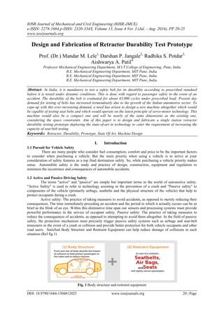
- 1. IOSR Journal of Mechanical and Civil Engineering (IOSR-JMCE) e-ISSN: 2278-1684,p-ISSN: 2320-334X, Volume 13, Issue 4 Ver. I (Jul. - Aug. 2016), PP 20-25 www.iosrjournals.org DOI: 10.9790/1684-1304012025 www.iosrjournals.org 20 | Page Design and Fabrication of Retractor Durability Test Prototype Prof. (Dr.) Mandar M. Lele1, Darshan P. Jangale2, Radhika S. Potdar3, Aishwarya A. Patil4 Professor Mechanical Engineering Department, M.I.T.College of Engineering, Pune, India B.E. Mechanical Engineering Department, MIT Pune, India. B.E. Mechanical Engineering Department, MIT Pune, India. B.E. Mechanical Engineering Department, MIT Pune, India. Abstract: In India, it is mandatory to test a safety belt for its durability according to prescribed standard before it is tested under dynamic conditions. This is done with regard to passenger safety in the event of an accident. The durability of the belt is evaluated for about 45,000 cycles under prescribed load. Present day demand for testing of belts has increased tremendously due to the growth of the Indian automotive sector. To cope-up with this ever-increasing demand, a need has arisen to design a new machine altogether which would be capable of testing seat belts and which would operate on the latest principle of servo-motor technology. This machine would also be a compact one and will be nearly of the same dimensions as the existing one, considering the space constraints. Aim of this paper is to design and fabricate a single station retractor durability testing prototype deploying the state-of-art in technology to cater the requirement of increasing the capacity of seat belt testing. Keywords: Retractor, Durability, Prototype, State Of Art, Machine Design I. Introduction 1.1 Pursuit for Vehicle Safety There are many people who consider fuel consumption, comfort and price to be the important factors to consider when purchasing a vehicle. But the main priority when using a vehicle is to arrive at your consideration of safety features as a top final destination safely. So, while purchasing a vehicle priority makes sense. Automobile safety is the study and practice of design, construction, equipment and regulation to minimize the occurrence and consequences of automobile accidents. 1.2 Active and Passive Driving Safety The terms "active" and "passive" are simple but important terms in the world of automotive safety. "Active Safety" is used to refer to technology assisting in the prevention of a crash and "Passive safety" to components of the vehicle (primarily airbags, seatbelts and the physical structure of the vehicle) that help to protect occupants during a crash. Active safety: The practice of taking measures to avoid accidents, as opposed to merely reducing their consequences. The time immediately preceding an accident and the period in which it actually occurs can be as brief as the blink of an eye. Within this diminutive time span our sensors and processing systems must provide powerful performance in the service of occupant safety. Passive safety: The practice of taking measures to reduce the consequences of accidents, as opposed to attempting to avoid them altogether. In the field of passive safety, the protection mechanism must precisely trigger passive safety systems such as airbags and seat-belt tensioners in the event of a crash or collision and provide better protection for both vehicle occupants and other road users. Satisfied Body Structure and Restraint Equipment can help reduce damage of collisions in each situation (Ref fig 1) Fig. 1 Body structure and restraint equipment
- 2. Design and Fabrication of Retractor Durability Test Protoype DOI: 10.9790/1684-1304012025 www.iosrjournals.org 21 | Page 1.3 Basic Retractor Durability Test Rig. Fig. 2 Basic Retractor Durability Test Rig. 1.4 The elements of Retractor Durability Test Rig are- Alternating Current Motor. Gear Box. Eccentric Arm. Bungee. Pneumatic Cylinder. Proximity Switches. Counters. 1.5 Limitations of Current Retractor Durability Test Mounting of Retractor with various opening angle is not possible. Achieving Different Percentage of Webbing Extraction Retraction length is not possible. Pneumatic Actuation fails at some instances. After the fifth cycle snatch occurs sometimes the snatch occurs for the preceding cycle also. The seatbelt slips from roller during the test. 1.6 Optimization Suggestions Using Stepper motor instead of Geared D.C. motor. Replacing Bungee with spring system. Produce a snatch by pneumatic actuator after every 4th cycle. Detection of pneumatic actuation using proximity sensor-1. The snatch produced causes displacement of drum pulley by approx. 6cm, detected by proximity sensor -2. These two proximity sensor outputs effectively assure proper instance of snatch. Failures of occurrence in snatch will be detected, counted and displayed throughout and after the test process. If the failure count exceeds a predetermined count, test procedure will be stopped and notified. II. Design of New Prototype 2.1 Calculating the selection parameters for pneumatic cylinder- We have to apply a force of 0.85g (10N) force on the retractor in order to achieve the emergency locking. When the emergency lock occurs a force of 50N is generated. This Force we have calculated by using the Force calculation meter. So, in total we have to apply a force of 60N using pneumatic cylinder. The stroke length required is 60mm.The pressure of the air used in pneumatic cylinder is 6bar. Force =60N Force= 𝑃𝑟𝑒𝑠𝑠𝑢𝑟𝑒 × 𝐴𝑟𝑒𝑎 Pressure =6bar=0.6N/mm2 Area= 𝐹𝑜𝑟𝑐𝑒 ÷ 𝐴𝑟𝑒𝑎 Area=60 ÷ 6 Area=100mm2 Area= 𝜋 × 𝐷2 ÷ 4 𝐷2 = 4 × 100 ÷ 𝜋 D=11.28mm Cylinder Diameter=20mm Stroke Length=60mm
- 3. Design and Fabrication of Retractor Durability Test Protoype DOI: 10.9790/1684-1304012025 www.iosrjournals.org 22 | Page 2.2 Selection parameters for F-R-L Converting the 0.85g to force in Newton. Force=𝑀𝑎𝑠𝑠 × 𝐴𝑐𝑐𝑒𝑙𝑒𝑟𝑎𝑡𝑖𝑜𝑛 Force=3 × 0.85 × 9.81 Force=25.0155N The Extraction velocity of the pneumatic cylinder Velocity= 𝑆𝑡𝑟𝑜𝑘𝑒 𝐿𝑒𝑛𝑔𝑡 ÷ 𝑇𝑖𝑚𝑒 Velocity=60 ÷ 1 Velocity=60mm/sec Flow Rate, Q=𝐴𝑟𝑒𝑎 × 𝑉𝑒𝑙𝑜𝑐𝑖𝑡𝑦 Q= 𝜋 ÷ 4 × 𝑑2 × 𝑉𝑒𝑙𝑜𝑐𝑖𝑡𝑦 Q=5.92 × 10⁻³ 𝑚3 𝑠𝑒𝑐. Soothe F-R-L unit is selected using the above value of flow rate. 2.3 Spring Considering, types of end of the Helical Compression spring to be Square and Ground end. Material- 302Stainless Steel Ultimate Tensile Strength=703MPa Modulus of Rigidity=77.2GPa Stresses in Helical Spring Resultant Shear Stress: T=𝐾 𝑤 8 × 𝐹 × 𝐷 ÷ 𝜋 × 𝑑3 Wahl Shear Stress Factor, 𝐾 𝑤 = 4𝐶 − 1 ÷ 4𝐶 − 4 + 0.615 ÷ 𝐶 × 1.083 Here, C=Spring Index=10. 𝐾 𝑤 = 1.144 𝑇𝑎𝑙𝑙 = 0.35 × 𝑆 𝑢𝑡 × 𝑁𝑓 𝑆 𝑢𝑡 =703N/mm2 𝑇𝑎𝑙𝑙 = 0.35 × 703 ÷ 1.5 𝑇𝑎𝑙𝑙 =164.033N/mm2 Now, 𝑑3 = 1.144 × 10 × 8 × 70 ÷ 164.033 × 𝜋 d=2.31mm=2.3mm Wire Diameter Of The spring Mean Coil Diameter C=𝐷 ÷ 𝑑 D=𝐶 × 𝑑 D=10 × 2.3 D=23mm Number of Coils According to Hooks law, Force=𝑘 × 𝐷𝑖𝑠𝑝𝑙𝑎𝑐𝑒𝑚𝑒𝑛𝑡 Spring Stiffness, K=𝐹𝑚𝑎𝑥 ÷ 𝐷𝑒𝑓𝑙𝑒𝑐𝑡𝑖𝑜𝑛 Deflection=60mm K=70 ÷ 60 K=1.167 N/mm2. Now, K= 𝐺 × 𝑑 ÷ 8 × 𝐶3 × 𝑛 n= 𝐺 × 𝑑 ÷ 8 × 𝐶3 × 𝐾 n= 77.2 × 103 × 2.31 ÷ 8 × 103 × 1.67 n=13.344=13=Number of Coils For, Square and Ground Ends, n'=n+2=13+2=15 n' =15 Solid Length LS=𝑛′ × 𝑑 LS=15×2.31=34.65=35mm
- 4. Design and Fabrication of Retractor Durability Test Protoype DOI: 10.9790/1684-1304012025 www.iosrjournals.org 23 | Page LS=35mm Free Length LF=LS+Deflection LF=35+60 LF=95mm 2.4 Asme Code for Design of Shaft Since the loads on most shafts in connected machinery are not constant, it is necessary to make proper allowance for the harmful effects of load fluctuations According to ASME code permissible values of shear stress may be calculated from various relations. Tall = 0.18× 𝑆 𝑢𝑡 = 0.18 × 841 = 151.38 N/mm OR Tall = 0.3× 𝑆𝑦𝑡 =0.3 × 247 =74.1 N/mm2 Considering minimum of the above values Tall = 74.1 N/mm2 We get, Maximum moment, M=4200N-mm Torque acting on the shaft= 40 ÷ 2 × 80=1600N-mm 𝑇𝑎𝑙𝑙 = 16𝑇𝑒 ÷ 𝜋 × 𝑑3 𝑇𝑒 = 𝐾𝑏 × 𝑀 2 + 𝐾𝑡 × 𝑇 2 2 𝑇𝑒=8988.88 N-mm Now, 𝑑3 = 16 × 8988.88 ÷ 𝜋 × 74.1 d=8.51mm Assuming, safety we take the shaft diameter to be 15mm. III. SIMULATION Fig.3 Displacement result
- 5. Design and Fabrication of Retractor Durability Test Protoype DOI: 10.9790/1684-1304012025 www.iosrjournals.org 24 | Page Fig.4 Yield Strength Result Fig. 5 Yield Strength Result Fig.6 Displacement Result
- 6. Design and Fabrication of Retractor Durability Test Protoype DOI: 10.9790/1684-1304012025 www.iosrjournals.org 25 | Page IV. Fabricated Prototype Fig.7 Fabricated Model V. Conclusion In this paper the stated objective to design and fabricate a single station retractor durability testing prototype deploying the state-of-art in technology to cater the requirement of increasing the capacity of seat belt testing. The paper confined to carry out the selection with justification and validation of the setup by developing 3D model of machine and related design calculations. It is anticipated that our design centric efforts would contribute to some extent in realizing the objectives of the modifying the retractor durability test machines. VI. Future Scope We can make the prototype more successful by using linear bearings instead of spring rail system. This will make the snatch more accurate and the compensation can of seat belt length will be precise. Automation of the machine will be a helpful for the development of machine. Reducing the weight of front frame will also be a good option. References [1]. Pneumatic System by S.R.Majumdar [2]. Machine Design Data Book by V.B.Bhandari [3]. Stepper Motors : Fundamentals, Applications And Design by V.V.Athani [4]. P.S.G. Design Data book [5]. Wikipedia [6]. Seat belt retractor Patent US 5526996 A