Tensile structures and Pneumatic Structures
•
2 likes•3,804 views

New Age Materials and Construction

Recommended
More Related Content
What's hot
What's hot (20)
Similar to Tensile structures and Pneumatic Structures
Similar to Tensile structures and Pneumatic Structures (20)
More from Geeva Chandana
More from Geeva Chandana (20)
Recently uploaded
Recently uploaded (20)
Tensile structures and Pneumatic Structures
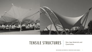
- 1. TENSILE STRUCTURES New Age Materials and Construction NEW AGE MATERIALS AND CONSTRUCTION | PRESENTATION BY AR.GEEVA CHANDANA | 1
- 2. TENSILE STRUCTURES •The term tensile structures describes the category of buildings in which the load bearing capacity is achieved through tension stress in the majority of the components, such as cables, technical fabrics or foils. •It can also be defined as a structure where the exterior shell is a fabric material spread over a framework. The fabric is maintained in tension in all directions to provide stability. •The only exception is represented by rigid boundaries and structural members which are generally subjected to compression and bending. •Tension structures are commonly subdivided in boundary tensioned membranes, pneumatic structures and pre- stressed cable nets and beams. NEW AGE MATERIALS AND CONSTRUCTION | PRESENTATION BY AR.GEEVA CHANDANA | 2
- 3. TENSILE STRUCTURES •Tensile structure is the term usually used to refer to the construction of roofs using a membrane held in place on steel cables. •Their main characteristics are the way in which they work under stress tensile, their ease of pre-fabrication, their ability to cover large spans, and their malleability. •This structural system calls for a small amount of material thanks to the use of thin canvases, which when stretched using steel cables, create surfaces capable of overcoming the forces imposed upon them. NEW AGE MATERIALS AND CONSTRUCTION | PRESENTATION BY AR.GEEVA CHANDANA | 3
- 4. TENSILE STRUCTURES : HISTORY Historically inspired by some of the first man-made shelters—such as the black tents first developed using camel leather by the nomads of the Sahara Desert, Saudi Arabia, and Iran, as well as the structures used by Native American tribes—tensile structures offer a range of positive benefits compared to other structural models. Romans even covered the Colosseum with massive canopies, hoisted by an intricate system of pulleys, to protect the audience from the elements. NEW AGE MATERIALS AND CONSTRUCTION | PRESENTATION BY AR.GEEVA CHANDANA | 4
- 5. TENSILE STRUCTURES : HISTORY •Predominantly used in coverings of sports centers, of arenas, and industrial and agroindustrial constructions, tensile structures are based on the old systems used during the Roman Empire. •However, from the Roman period until the mid-20th century, due to the low demand, usability, and lack of manufacturers of cables, canvasses, and connections capable of resisting the forces generated, there were few technological advances. •It was only after the Industrial Revolution and the triggering of the era of Fordism that new developments were able to meet the intrinsic needs of this construction system. •The low cost of mass production and the demand for systems capable of adapting to the most varied terrains with large spans, such as circus tents for example, encouraged the development of the technique. NEW AGE MATERIALS AND CONSTRUCTION | PRESENTATION BY AR.GEEVA CHANDANA | 5
- 6. NEW AGE MATERIALS AND CONSTRUCTION | PRESENTATION BY AR.GEEVA CHANDANA | 6
- 7. NEW AGE MATERIALS AND CONSTRUCTION | PRESENTATION BY AR.GEEVA CHANDANA | 7
- 8. NEW AGE MATERIALS AND CONSTRUCTION | PRESENTATION BY AR.GEEVA CHANDANA | 8
- 9. TENSILE STRUCTURES : TYPES •There are three different main classifications in the field of tensile construction systems: membrane tensioned structures, mesh tensioned, and pneumatic structures. •MEMBRANE TENSIONED STRUCTURES: A membrane is held by cables, allowing the distribution of the tensile stresses through its own form. •MESH TENSIONED STRUCTURES: A mesh of cables carries the intrinsic forces, transmitting them to separate elements, for example, sheets of glass or wood. •PNEUMATIC STRUCTURES: A protective membrane is supported by means of air pressure. NEW AGE MATERIALS AND CONSTRUCTION | PRESENTATION BY AR.GEEVA CHANDANA | 9
- 10. NEW AGE MATERIALS AND CONSTRUCTION | PRESENTATION BY AR.GEEVA CHANDANA | 10
- 11. NEW AGE MATERIALS AND CONSTRUCTION | PRESENTATION BY AR.GEEVA CHANDANA | 11
- 12. NEW AGE MATERIALS AND CONSTRUCTION | PRESENTATION BY AR.GEEVA CHANDANA | 12
- 13. NEW AGE MATERIALS AND CONSTRUCTION | PRESENTATION BY AR.GEEVA CHANDANA | 13
- 14. NEW AGE MATERIALS AND CONSTRUCTION | PRESENTATION BY AR.GEEVA CHANDANA | 14
- 15. NEW AGE MATERIALS AND CONSTRUCTION | PRESENTATION BY AR.GEEVA CHANDANA | 15
- 16. NEW AGE MATERIALS AND CONSTRUCTION | PRESENTATION BY AR.GEEVA CHANDANA | 16
- 17. NEW AGE MATERIALS AND CONSTRUCTION | PRESENTATION BY AR.GEEVA CHANDANA | 17
- 18. NEW AGE MATERIALS AND CONSTRUCTION | PRESENTATION BY AR.GEEVA CHANDANA | 18
- 19. NEW AGE MATERIALS AND CONSTRUCTION | PRESENTATION BY AR.GEEVA CHANDANA | 19
- 20. NEW AGE MATERIALS AND CONSTRUCTION | PRESENTATION BY AR.GEEVA CHANDANA | 20
- 21. NEW AGE MATERIALS AND CONSTRUCTION | PRESENTATION BY AR.GEEVA CHANDANA | 21
- 22. TENSILE STRUCTURES : CONSTRUCTION DETAILS •Structurally, the system is formalized by combining three elements: membranes, rigid structures such as pole and masts, and cables. •The membranes of PVC-coated polyester fibers have greater ease in factory production and installation; lower cost; and medium durability—around 10 years. •PTFE (Polytetrafluoroethylene)-coated glass fiber membranes have superior durability—around 30 years; and greater resistance to the elements (sun, rain, and winds); however, they require skilled labor. •There are two types of support: direct and indirect. The direct supports are those in which the construction is arranged directly on the rest of the building structure, while the second case is arranged from a raised point such as a mast. NEW AGE MATERIALS AND CONSTRUCTION | PRESENTATION BY AR.GEEVA CHANDANA | 22
- 23. TENSILE STRUCTURES : CONSTRUCTION DETAILS •The cables, which are responsible for the distribution of the tensile stresses and the hardening of the canvasses, are classified in one of two ways according to the action which they perform: load-bearing and stabilizing. •Both types of cable cross orthogonally, ensuring strength in two directions and avoiding deformations. •The load-bearing cables are those that directly receive the external loads, fixed at the highest points. •On the other hand, the stabilizing cables are responsible for strengthening the load- bearing cables and cross the load-bearing cables orthogonally. •It is possible to avoid attaching the stabilizing cables to the ground by using a peripheral fixation cable. •The nomenclatures for different cables are generated according to their position: a ridge-line cable refers to the uppermost cable; while valley cables are fixed below all other cables; radial cables are stabilizer cables in the form of a ring. •Ridge-line cables support gravitational loads while valley cables support wind loads. NEW AGE MATERIALS AND CONSTRUCTION | PRESENTATION BY AR.GEEVA CHANDANA | 23
- 24. FABRIC STRUCTURES : TYPES OF ROOF •SADDLE ROOF •MAST SUPPORTED •ARCH SUPPORTED •COMBINATIONS NEW AGE MATERIALS AND CONSTRUCTION | PRESENTATION BY AR.GEEVA CHANDANA | 24
- 25. FABRIC STRUCTURES : SADDLE ROOF The roof plan, taken directly from the structural engineering working drawings, illustrates the roof configuration and its components. Section through the project showing the stage roof tucked under the auditorium roof. •Four or more point system when the fabric is stretched between a set of alternating high and low points. NEW AGE MATERIALS AND CONSTRUCTION | PRESENTATION BY AR.GEEVA CHANDANA | 25
- 26. FABRIC STRUCTURES : MAST SUPPORTED •Tent-like in appearance, mast supported structures typically have one or sometimes several peaks that are supported by either interior or perimeter masts. •The fabric is attached to the interior mast by special connections, usually a bale ring or cable loop. •Mast-supported structures can also be supported by adjacent buildings. The peaks of a mast supported structure are determined by the design and how the fabric is attached. •Openings are typically ovoid or elliptical. The fabric that extends from the top of the opening is seamed and can necessitate patterning. •Mast supported systems are suitable for long span roofs. NEW AGE MATERIALS AND CONSTRUCTION | PRESENTATION BY AR.GEEVA CHANDANA | 26
- 27. FABRIC STRUCTURES : ARCH SUPPORTED ROOF •Curved compression members are used as the main supporting elements and cross arches are used for lateral stability. •In a plane arch, large differences between the thrust lines and the main geometry will produce large bending moments that in turn produce large changes in shape and high stresses in the arch chord section. •One method to significantly reduce these effects is to tie or restrain points along the arch chord to reduce the initial large deformations of the chord. •The buckling length of the arch chord can also be reduced by discretely or continuously supporting the chord with tension elements or systems comprised of cables or membranes. NEW AGE MATERIALS AND CONSTRUCTION | PRESENTATION BY AR.GEEVA CHANDANA | 27
- 28. NEW AGE MATERIALS AND CONSTRUCTION | PRESENTATION BY AR.GEEVA CHANDANA | 28
- 29. FABRIC STRUCTURES : COMBINATIONS •Combination of several support types. NEW AGE MATERIALS AND CONSTRUCTION | PRESENTATION BY AR.GEEVA CHANDANA | 29
- 30. FABRIC STRUCTURES : COMPONENTS BASE PLATE •Connection to concrete foundation pillar MEMBRANES •Forms the enclosure of the structure. Connections can be glued or heat welded : PVC coated polyester (polyvinylchloride) Silicon coated glass Teflon coated glass P.T.F.E (polytetrafluroethylene) BALE RING/ MEMBRANE PLATE Provide a link between the membrane and structural elements.. Bale rings are used at the top of conical shapes. Membrane plates accept centenary cables and pin connection hardware. NEW AGE MATERIALS AND CONSTRUCTION | PRESENTATION BY AR.GEEVA CHANDANA | 30
- 31. FABRIC STRUCTURES : COMPONENTS TYPES OF FABRIC MEMBRANE PVC : •Less expensive •15 to 20 year life span •Easy to erect TEFLON GLASS: •Similar to silicon glass, less brittle SILICON GLASS: •Higher tensile strength •Brittle, subject to damage from flexing 30+ year life span NEW AGE MATERIALS AND CONSTRUCTION | PRESENTATION BY AR.GEEVA CHANDANA | 31
- 32. NEW AGE MATERIALS AND CONSTRUCTION | PRESENTATION BY AR.GEEVA CHANDANA | 32
- 33. NEW AGE MATERIALS AND CONSTRUCTION | PRESENTATION BY AR.GEEVA CHANDANA | 33
- 34. Tripod head with centenary cables Centenary cables at a side connection Extruded section with membrane plate and centenary cablesTensioner NEW AGE MATERIALS AND CONSTRUCTION | PRESENTATION BY AR.GEEVA CHANDANA | 34
- 35. Edge c able with c lamps. Used mainly for PTFE- coated fiber glass fabric , but also for PVC- coated poly ester fabric when edge spans are longer than 20 m. CABLECLAMPS NEW AGE MATERIALS AND CONSTRUCTION | PRESENTATION BY AR.GEEVA CHANDANA | 35
- 36. NEW AGE MATERIALS AND CONSTRUCTION | PRESENTATION BY AR.GEEVA CHANDANA | 36
- 37. Bale rings are a good way to control stresses in fabric roof at high or low po ints. Used at high points they must be covered to make the structure watertight. If used at low points, they canbe used to gather rainwater and snow for redistribution on site. Channel (with grommets) and lacing. Used with PVC- coated polyester fabric where the edge has grommets spaced at frequent intervals. Rope is laced thro ugh the grommets and to a tie rod within the channel. Water dreainage via Membrane plates NEW AGE MATERIALS AND CONSTRUCTION | PRESENTATION BY AR.GEEVA CHANDANA | 37
- 38. NEW AGE MATERIALS AND CONSTRUCTION | PRESENTATION BY AR.GEEVA CHANDANA | 38
- 39. NEW AGE MATERIALS AND CONSTRUCTION | PRESENTATION BY AR.GEEVA CHANDANA | 39
- 40. NEW AGE MATERIALS AND CONSTRUCTION | PRESENTATION BY AR.GEEVA CHANDANA | 40
- 41. NEW AGE MATERIALS AND CONSTRUCTION | PRESENTATION BY AR.GEEVA CHANDANA | 41
- 42. NEW AGE MATERIALS AND CONSTRUCTION | PRESENTATION BY AR.GEEVA CHANDANA | 42
- 43. NEW AGE MATERIALS AND CONSTRUCTION | PRESENTATION BY AR.GEEVA CHANDANA | 43
- 44. NEW AGE MATERIALS AND CONSTRUCTION | PRESENTATION BY AR.GEEVA CHANDANA | 44
- 45. NEW AGE MATERIALS AND CONSTRUCTION | PRESENTATION BY AR.GEEVA CHANDANA | 45
- 46. NEW AGE MATERIALS AND CONSTRUCTION | PRESENTATION BY AR.GEEVA CHANDANA | 46
- 47. NEW AGE MATERIALS AND CONSTRUCTION | PRESENTATION BY AR.GEEVA CHANDANA | 47
- 48. NEW AGE MATERIALS AND CONSTRUCTION | PRESENTATION BY AR.GEEVA CHANDANA | 48
- 49. NEW AGE MATERIALS AND CONSTRUCTION | PRESENTATION BY AR.GEEVA CHANDANA | 49
- 50. NEW AGE MATERIALS AND CONSTRUCTION | PRESENTATION BY AR.GEEVA CHANDANA | 50
- 51. NEW AGE MATERIALS AND CONSTRUCTION | PRESENTATION BY AR.GEEVA CHANDANA | 51
- 52. NEW AGE MATERIALS AND CONSTRUCTION | PRESENTATION BY AR.GEEVA CHANDANA | 52
- 53. NEW AGE MATERIALS AND CONSTRUCTION | PRESENTATION BY AR.GEEVA CHANDANA | 53
- 54. NEW AGE MATERIALS AND CONSTRUCTION | PRESENTATION BY AR.GEEVA CHANDANA | 54
- 55. TENSILE STRUCTURES ADVANTAGES DISADVANTAGES Longer life cycles of materials. Little to no rigidity Materials can be re-used in form. Loss of tension is dangerous for stability Most materials are completely recyclable. Thermal values limit use Less impact on site. Less construction debris after demolition. Unique designs Lightweight and flexible Environmentally sensitive High strength weight ratio NEW AGE MATERIALS AND CONSTRUCTION | PRESENTATION BY AR.GEEVA CHANDANA | 55
- 56. PNEUMATIC STRUCTURES NEW AGE MATERIALS AND CONSTRUCTION | PRESENTATION BY AR.GEEVA CHANDANA | 56
- 57. PNEUMATIC STRUCTURES •Pneumatics are tensile structures par excellence, since only with them it is possible to have all elements working exclusively in tension. •As what usually occurs with tensile structures, in a pneumatic structure, shape cannot be imposed, since membranes do not withstand bending, and thus geometry and loads have to interact until a equilibrium configuration is reached. •The design of a pneumatic structure involves the determination of an initial or viable configuration, encompassing the structure’s shape and the corresponding stress field. •Besides, the viable shape has to accommodate both architectonic requirements (form and function) and – minding materials – structural requirements (resistance and stability). •The design of the structure is necessarily integrated to analysis, in a process that encompasses procedures for shape finding, patterning and load analysis. NEW AGE MATERIALS AND CONSTRUCTION | PRESENTATION BY AR.GEEVA CHANDANA | 57
- 58. • Pneumatic structure is a membrane which carries load developed from the tensile stresses. • Its stabilization is done by pre- stressing the membrane either by a) Applying an external force which pulls the membrane taut b) Internal pressurizing if the membrane is volume enclosing. Such structures are called “pneumatic structures”. • These structures can create artificial environments adaptable to human use . • The pneumatic forms are bound to increase in popularity, owing to the tremendous freedom they provide to the architects in designing large free spaces within them. • The word pneumatic is derived from the greek word “pneuma” (meaning breath of air), thus these are the structure which are supported by air. • Although pneumatic structures have been used by mankind for thousand of years; it was only introduced in the building technology about 40 years ago. 1. Its principle is the use of relatively thin membrane supported by a pressure difference. 2. Through increasing the inside air pressure not only the dead weight of the space envelope is balanced, but the membrane is stressed to a point where it cannot be indented by asymmetrical loading. PRINCIPLE PNEUMATIC STRUCTURES
- 59. PNEUMATIC STRUCTURES : TYPES AIR INFLATED STRUCTURES AIR SUPPORTED STRUCTURES It consist of a single membrane (enclosing a functionally useful space) which is supported by a small internal pressure difference. The internal volume of a building air is consequently at a pressure higher than atmospheric. • They have air higher than the atmospheric pressure supporting the envelope. • Air locks or revolving doors help to maintain the internal pressure. • Air must be constantly provided. • Life span of 20 – 25 years. • Relatively low cost. • They are either anchored to the ground or to a wall so that leakage is prevented. • They have relative low cost and they can be installed easily. It is supported by pressurized air contained within inflated building element. The pressurized air in the pillow serves only to stabilizing the load carrying membrane. The covered space is not pressurized. • Supporting frames consist of air under high pressure. • Internal pressure of building remains at atmospheric pressure. • There is no restrictions in number and size of openings. • It has the ability to support itself. • They have potential to support an attached structure.
- 60. • The weight of the structure as compared to the area it covers is very less. • The weight of the membrane roof, even when it is stiffened by cables, is very small. • Low air pressure is sufficient to balance it. PNEUMATIC STRUCTURES: GENERAL CHARACTERISTICS LIGHT-WEIGHT • There is no theoretical maximum span. • To span a distance of 36 m for a normal building is hard while such spans are quite possible for pneumatics. SPAN • Pneumatic structures are safer than any other structure. Otherwise, a proper care should be taken while establishing. • They are fire resistance structures. • Suitable for temporary constructions. • 1 km² area can be brought down in 6 hours and can be establish in less than 10 hours. QUICK ERECTION & DISMANTLING • It is not expensive when it is used as temporary structures. ECONOMY • If envelope is made up of transparent material, good natural light enter into the structure. • Around 50% – 80% of sunlight can be obtained. SAFETY GOOD NATURAL LIGHTING • In most cases, pressure of not more than 80-100mm and not less than 60mm. • Man can withstand pressures between 0.20 atm to 3 atm. Therefore no health hazard is presented by continuous stay in a pneumatic structure. HUMAN HEALTH
- 61. • They can be made up of different materials. • Cannot be used as one continuous material. • Material are seamed together by sealing, heat bonding or mechanical jointing. • The design of the envelope depends on an evenly pressurized environment. PNEUMATIC STRUCTURES : SYSTEM COMPONENTS ENVELOPE • They act as the supporting system. • They experience tension force due to the upward force of the air. • Can be placed in one or two directions to create a network and for better stability. • They do not fail since they are pulled tight enough to absorb the external loads. CABLE SYSTEM • It is used to supply and maintain internal pressure inside the structure. • Fans, blowers or compressors are used for constant supply of air. • The amount of air required depends on the weight of the material and the wind pressure. PUMPING EQUIPMENT • Doors can be ordinary doors or airlocks. • Airlock minimize the chances of having an unevenly pressurized environment. ENTRANCE
- 62. • Pneumatic structures are secured to ground using heavy weights, ground anchors or attached to a foundation. • Weight of the material and the wind loads are used to determine the most appropriate anchoring system. • For bigger structures, reinforcing cables or nets are used. • For a dependent pneumatic structure (roof only air supported structure) the envelope is anchored to the main structure. • When anchoring is done to soil, the cable is attached to the anchor directly inserted and frictional forces of the soil to hold it down. • Soil anchoring systems include screw, disk, expanding duckbill and arrowhead anchors. FOUNDATION PNEUMATIC STRUCTURES : SYSTEM COMPONENTS
- 63. • Wind and Snow loads are the primary loads that are acting on pneumatic structures. • They are anchored very tight to the ground, so no horizontal forces are exerted to the envelope. • As pneumatic structures are tensile, the envelope has the ability to gain stiffness in order to withstand the loads acting on them. PNEUMATIC STRUCTURES : LOADING • Wind loads produce a lateral force on the structures and snow load causes downward forces on envelope. • Pneumatic structures are designed to withstand wind load of 120 mph and a snow load of 40 pounds/yard. AIR SUPPORTED STRUCTURES AIR INFLATED STRUCTURES
- 64. PNEUMATICSTRUCTURES : CLASSIFICATION • Pneumatic Structures use either positive pressure or negative pressure. • In Positive Pressure System, the membrane is always curved outwards, whereas in Negative Pressure Systems the membrane is curved inwards. • Being curved inwards there is a tendency of water logging & snow accumulation. • Moreover, negative pressure systems require high supports at the edge or in the center which makes it more expensive. Pneumatic Structures can be further subdivided as:- A. Type of Differential Pressure B. Degree of Differential Pressure TYPE OF DIFFERENTIAL PRESSURE C. Type of Surface Curvature D. Proportions DEGREE OF DIFFERENTIAL PRESSURE LOW PRESSURE SYSTEMS These systems are provided with low pressure air; hence have to be provided with continuous supply of air. Example: Air Supported Structures. HIGH PRESSURE SYSTEMS Used for easy erection & dismantling; the pressure difference is b/w 2000-7000mm of water pressure (100 to 1000 times) low pressure systems. These high pressure air inflated systems are either having a single valve system or a double valve systems which avoids it’s collapse. AIR SUPPORTED STRUCTURES AIR INFLATED STRUCTURES
- 65. NEW AGE MATERIALS AND CONSTRUCTION | PRESENTATION BY AR.GEEVA CHANDANA | 65
- 66. NEW AGE MATERIALS AND CONSTRUCTION | PRESENTATION BY AR.GEEVA CHANDANA | 66
- 67. a. Single curved b. Doubly curved in the same direction or synclastics c. Doubly curved in opposite direction or anticlastic TYPE OF SURFACE CURVATURE These structures can also be classified according to the types of curvature on the outer surface, PROPORTIONS On the basis of different proportions, pneumatic structures can be:- a. Two dimension of similar size and one larger dimension Example: Tubes, Masts, Columns, Towers b. Two dimensions of similar size and one smaller dimension Example: Cushions , Lenses, Mattresses c. Three dimensions of similar size Example: Balloons, Balls, Spheres, Bubbles DOUBLY CURVED IN THE SAME DIRECTION DOUBLY CURVED IN OPPOSITE DIRECTION PNEUMATICSTRUCTURES : CLASSIFICATION
- 68. • They high tensile strength, elastic behavior and durability. • Coated with Teflon or silicone to increase resistance to extreme temperatures and UV radiation. FIBERGLASS • Most common envelope material for smaller structures. • PVC-coated polyester is common for flexible, smaller air-supported structures. • The PVC is applied to the polyester using a bonding or adhesive agent. POLYESTER ETFE (ETHYLENE TETRAFLUOROETHYLENE) • It is very energy efficient because of transparency, insulation and UV resistance. • It is also light weight has an lifespan on 20 years and is recyclable. NYLON • Vinyl-coated nylon has more strength, durability and stretch than polyester. • They have a higher cost. ENVELOPE MATERIALS PNEUMATICSTRUCTURES : MATERIALS
- 69. • Materials for ballasts of smaller structures include sand bags, concrete blocks or bricks. • The ballasts must be placed around the perimeter of the structure to evenly distribute the load. BALLASTS ANCHOR MATERIALS The anchor material depends on the application and size of the pneumatic structure. STEEL CABLES • Steel wires are twisted into strands which are then twisted around a core to form the cable. PNEUMATICSTRUCTURES : MATERIALS
- 70. SPORTS & RECREATIONAL CENTRES Ability to span great distances without beams and columns. MILITARY STRUCTURES For storage, for emergency medical operations & To protect radar stations from weather conditions EXHIBITION & CONVENTION CENTRES STRUCTURES FOR BOTANICAL GARDENS, ZOOLOGICAL GARDENS, GREENHOUSE, HOTHOUSE TRAVERSING BRIDGE STRUCTURES PNEUMATICSTRUCTURES : APPLICATIONS
- 71. NEW AGE MATERIALS AND CONSTRUCTION | PRESENTATION BY AR.GEEVA CHANDANA | 71
- 72. NEW AGE MATERIALS AND CONSTRUCTION | PRESENTATION BY AR.GEEVA CHANDANA | 72
- 73. PNEUMATIC STRUCTURES : ADVANTAGES & DISADVANTAGES ADVANTAGES DISADVANTAGES • Light weight • Covers large spans without internal supports • Rapid assembly and have low initial and operating cost • Portability • Need for continuous maintenance of excess pressure in the envelope • Relatively short service life • Continuous operation of fans to maintain pressure • Cannot reach the insulation values of hard-walled structures CONCLUSION a) Pneumatic structures have found wide range of application. b) They are best suited for small and temporary construction. c) They can be quickly erected and dismantled. d) Provoke fascination among observers and bystanders.
- 74. NEW AGE MATERIALS AND CONSTRUCTION | PRESENTATION BY AR.GEEVA CHANDANA | 74
- 75. NEW AGE MATERIALS AND CONSTRUCTION | PRESENTATION BY AR.GEEVA CHANDANA | 75
- 76. NEW AGE MATERIALS AND CONSTRUCTION | PRESENTATION BY AR.GEEVA CHANDANA | 76
- 77. NEW AGE MATERIALS AND CONSTRUCTION | PRESENTATION BY AR.GEEVA CHANDANA | 77
- 78. NEW AGE MATERIALS AND CONSTRUCTION | PRESENTATION BY AR.GEEVA CHANDANA | 78
- 79. NEW AGE MATERIALS AND CONSTRUCTION | PRESENTATION BY AR.GEEVA CHANDANA | 79 Graphical representation of air-supported hall and hall constructed with airbeams
- 80. NEW AGE MATERIALS AND CONSTRUCTION | PRESENTATION BY AR.GEEVA CHANDANA | 80
- 81. NEW AGE MATERIALS AND CONSTRUCTION | PRESENTATION BY AR.GEEVA CHANDANA | 81
- 82. NEW AGE MATERIALS AND CONSTRUCTION | PRESENTATION BY AR.GEEVA CHANDANA | 82
- 83. NEW AGE MATERIALS AND CONSTRUCTION | PRESENTATION BY AR.GEEVA CHANDANA | 83
- 84. NEW AGE MATERIALS AND CONSTRUCTION | PRESENTATION BY AR.GEEVA CHANDANA | 84
- 85. NEW AGE MATERIALS AND CONSTRUCTION | PRESENTATION BY AR.GEEVA CHANDANA | 85
- 86. NEW AGE MATERIALS AND CONSTRUCTION | PRESENTATION BY AR.GEEVA CHANDANA | 86
- 87. NEW AGE MATERIALS AND CONSTRUCTION | PRESENTATION BY AR.GEEVA CHANDANA | 87
- 88. NEW AGE MATERIALS AND CONSTRUCTION | PRESENTATION BY AR.GEEVA CHANDANA | 88
- 89. NEW AGE MATERIALS AND CONSTRUCTION | PRESENTATION BY AR.GEEVA CHANDANA | 89
- 90. NEW AGE MATERIALS AND CONSTRUCTION | PRESENTATION BY AR.GEEVA CHANDANA | 90
- 91. NEW AGE MATERIALS AND CONSTRUCTION | PRESENTATION BY AR.GEEVA CHANDANA | 91
- 92. NEW AGE MATERIALS AND CONSTRUCTION | PRESENTATION BY AR.GEEVA CHANDANA | 92