1. ZJ COOLING SYSTEM 7-1
COOLING SYSTEM
CONTENTS
page page
DIAGNOSIS . . . . . . . . . . . . . . . . . . . . . . . . . . . . . 3 SERVICE PROCEDURES . . . . . . . . . . . . . . . . . . 11
ENGINE ACCESSORY DRIVE BELTS . . . . . . . . . 40 SPECIFICATIONS . . . . . . . . . . . . . . . . . . . . . . . . 50
ENGINE BLOCK HEATER . . . . . . . . . . . . . . . . . . 48
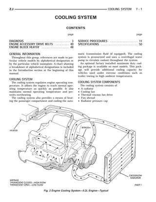
GENERAL INFORMATION matic transmission fluid (if equipped). The cooling
Throughout this group, references are made to par- system is pressurized and uses a centrifugal water
ticular vehicle models by alphabetical designation or pump to circulate coolant throughout the system.
by the particular vehicle nameplate. A chart showing An optional factory installed maximum duty cool-
a breakdown of alphabetical designations is included ing package is available on most models. This pack-
in the Introduction section at the beginning of this age will provide additional cooling capacity for
manual. vehicles used under extreme conditions such as
trailer towing in high ambient temperatures.
COOLING SYSTEM
The cooling system regulates engine operating tem- COOLING SYSTEM COMPONENTS
perature. It allows the engine to reach normal oper- The cooling system consists of:
ating temperature as quickly as possible. It also • A radiator
maintains normal operating temperature and pre- • Cooling fan
vents overheating. • Thermal viscous fan drive
The cooling system also provides a means of heat- • Fan shroud
ing the passenger compartment and cooling the auto- • Radiator pressure cap
Fig. 2 Engine Cooling System—5.2L Engine—Typical
2. 7-2 COOLING SYSTEM ZJ
• Thermostat
• Coolant reserve/overflow system
• Transmission oil cooler (if equipped with an auto-
matic transmission)
• Coolant
• Water pump
• Hoses and hose clamps
SYSTEM COOLANT ROUTING
For cooling system routings refer to (Figs. 1 or 2).
Fig. 1 Engine Cooling System—4.0L Engine—
Typical
3. ZJ COOLING SYSTEM DIAGNOSIS 7-3
DIAGNOSIS
INDEX
page page
DRB Scan Tool . . . . . . . . . . . . . . . . . . . . . . . . . . . . 4 Preliminary Checks . . . . . . . . . . . . . . . . . . . . . . . . . 4
On-Board Diagnostics (OBD) . . . . . . . . . . . . . . . . . . 3
ON-BOARD DIAGNOSTICS (OBD) It is possible that a DTC for a monitored circuit
may not be entered into memory even though a mal-
FOR CERTAIN COOLING SYSTEM function has occurred. Refer to On-Board Diagnostics
COMPONENTS (OBD) in Group 14, Fuel Systems for additional in-
The powertrain control module (PCM) has been formation.
programmed to monitor certain cooling system com-
ACCESSING DIAGNOSTIC TROUBLE CODES
ponents:
A stored Diagnostic Trouble Code (DTC) can be dis-
• If the engine has remained cool for too long a pe- played by cycling the ignition key On-Off-On-Off-On
riod, such as with a stuck open thermostat, a Diag- within three seconds and observing the malfunction
nostic Trouble Code (DTC) number 17 can be indicator lamp. This lamp is displayed on the instru-
observed at the malfunction indicator lamp. This ment panel as the CHECK ENGINE lamp (Fig. 3).
lamp is displayed on the instrument panel as the They can also be displayed through the use of the
CHECK ENGINE lamp (Fig. 3). Diagnostic Readout Box (DRB) scan tool. The DRB
connects to the data link connector in the engine
compartment (Fig. 4). For operation of the DRB, refer
to the appropriate Powertrain Diagnostic Procedures
service manual.
Fig. 3 Check Engine Lamp Location
If the problem is sensed in a monitored circuit of-
ten enough to indicate an actual problem, a DTC is
stored. The DTC will be stored in the PCM memory
for eventual display to the service technician. If the
problem is repaired or ceases to exist, the PCM can-
cels the DTC after 51 engine starts.
Certain criteria must be met for a DTC to be en-
tered into PCM memory. The criteria may be a spe-
cific range of engine rpm, engine temperature and/or Fig. 4 Data Link Connector Location—Typical
input voltage to the PCM. EXAMPLES:
A DTC indicates that the PCM has recognized an • If the lamp (Fig. 3) flashes 1 time, pauses and
abnormal signal in a circuit or the system. A DTC flashes 2 more times, a flashing Diagnostic Trouble
may indicate the result of a failure, but never iden- Code (DTC) number 12 is indicated. If this code is
tify the failed component directly. observed, it is indicating that the battery has been
disconnected within the last 50 key-on cycles. It
4. 7-4 COOLING SYSTEM DIAGNOSIS ZJ
could also indicate that battery voltage has been dis- • Increasing engine speed for more air flow is recom-
connected to the PCM. In either case, other DTC’s mended.
may have been erased. 2. TRAILER TOWING:
• If the lamp flashes 1 time, pauses and flashes 7 Consult Trailer Towing section of owners manual.
more times, a flashing Diagnostic Trouble Code Do not exceed limits.
(DTC) number 17 is indicated. 3. AIR CONDITIONING; ADD-ON OR AFTER
After any stored DTC information has been ob- MARKET:
served, the display will end with a flashing DTC A maximum cooling package should have been or-
number 55. This will indicate the end of all stored in- dered with vehicle if add-on or after market A/C is
formation. installed. If not, maximum cooling system compo-
nents should be installed for model involved per
ERASING TROUBLE CODES
After the problem has been repaired, use the DRB manufacturer’s specifications.
scan tool to erase a DTC. Refer to the appropriate 4. RECENT SERVICE OR ACCIDENT REPAIR:
Powertrain Diagnostic Procedures service manual for Determine if any recent service has been performed
operation of the DRB scan tool. on vehicle that may effect cooling system. This may
be:
DRB SCAN TOOL • Engine adjustments (incorrect timing)
For operation of the DRB scan tool, refer to the ap- • Slipping engine accessory drive belt(s)
propriate Powertrain Diagnostic Procedures service • Brakes (possibly dragging)
manual. • Changed parts (incorrect water pump rotating in
wrong direction)
PRELIMINARY CHECKS • Reconditioned radiator or cooling system refilling
(possibly under-filled or air trapped in system).
ENGINE COOLING SYSTEM OVERHEATING • Rubber and foam air seals not properly installed to
Establish what driving conditions caused the com- radiator or A/C condenser after a repair.
plaint. Abnormal loads on the cooling system such as • Upper and lower portions of radiator fan shroud
the following may be the cause. not tightly connected. All air must flow through the
1. PROLONGED IDLE, VERY HIGH AMBIENT radiator.
TEMPERATURE, SLIGHT TAIL WIND AT IDLE, If investigation reveals none of the previous
SLOW TRAFFIC, TRAFFIC JAMS, HIGH items as a cause for an engine overheating com-
SPEED, OR STEEP GRADES: plaint, refer to following Cooling System Diag-
Driving techniques that avoid overheating are: nosis charts.
• Idle with A/C off when temperature gauge is at These charts are to be used as a quick-reference
end of normal range. only. Refer to the group text for information.
5. ZJ COOLING SYSTEM DIAGNOSIS 7-5
COOLING SYSTEM DIAGNOSIS
6. 7-6 COOLING SYSTEM DIAGNOSIS ZJ
COOLING SYSTEM DIAGNOSIS (CONT.)
7. ZJ COOLING SYSTEM DIAGNOSIS 7-7
COOLING SYSTEM DIAGNOSIS (CONT.)
8. 7-8 COOLING SYSTEM DIAGNOSIS ZJ
COOLING SYSTEM DIAGNOSIS (CONT.)
9. ZJ COOLING SYSTEM DIAGNOSIS 7-9
COOLING SYSTEM DIAGNOSIS (CONT.)
10. 7 - 10 COOLING SYSTEM DIAGNOSIS ZJ
COOLING SYSTEM DIAGNOSIS (CONT.)
11. ZJ COOLING SYSTEM SERVICE PROCEDURES 7 - 11
SERVICE PROCEDURES
INDEX
page page
Automatic Transmission Oil Coolers . . . . . . . . . . . . 38 Refilling Cooling System . . . . . . . . . . . . . . . . . . . . 26
Coolant . . . . . . . . . . . . . . . . . . . . . . . . . . . . . . . . . 23 Testing Cooling System for Leaks . . . . . . . . . . . . . 26
Coolant Reserve/Overflow System . . . . . . . . . . . . . 28 Thermostat . . . . . . . . . . . . . . . . . . . . . . . . . . . . . . 20
Cooling System Cleaning/Reverse Flushing . . . . . . 26 Viscous Fan Drive—All Engines . . . . . . . . . . . . . . 36
Cooling System Fan . . . . . . . . . . . . . . . . . . . . . . . 35 Water Pump Bypass Hose—5.2L V-8 Engine . . . . . 18
Cooling System Hoses . . . . . . . . . . . . . . . . . . . . . 34 Water Pump Tests . . . . . . . . . . . . . . . . . . . . . . . . . 11
Draining Cooling System . . . . . . . . . . . . . . . . . . . . 25 Water Pumps—General Information . . . . . . . . . . . . 11
Radiator . . . . . . . . . . . . . . . . . . . . . . . . . . . . . . . . 30 Water Pumps—Removal/Installation . . . . . . . . . . . 12
Radiator Pressure Cap . . . . . . . . . . . . . . . . . . . . . 28
WATER PUMPS—GENERAL INFORMATION
A centrifugal water pump circulates coolant
through the water jackets, passages, intake manifold,
radiator core, cooling system hoses and heater core.
The pump is driven from the engine crankshaft by a
single serpentine drive belt on all engines.
The water pump impeller is pressed onto the rear
of a shaft that rotates in bearings pressed into the
housing. The housing has two small holes to allow
seepage to escape. The water pump seals are lubri-
cated by the antifreeze in the coolant mixture. No ad-
ditional lubrication is necessary.
CAUTION: All 4.0L 6-cylinder engines are equipped
with a reverse (counterclockwise) rotating water
pump and thermal viscous fan drive assembly. RE-
VERSE is stamped or imprinted on the cover of the
viscous fan drive and inner side of the fan. The let-
ter R is stamped into the back of the water pump
impeller (Fig. 1). Engines from previous model
years, depending upon application, may have been
equipped with a forward (clockwise) rotating water Fig. 1 Reverse Rotating Water Pump—4.0L
pump. Installation of the wrong water pump or vis- 6-Cylinder
cous fan drive will cause engine over heating. DRAINCOCK WITH THE SYSTEM HOT AND UNDER
PRESSURE. SERIOUS BURNS FROM THE COOL-
A quick test to determine if the pump is working is
to check if the heater warms properly. A defective wa- ANT CAN OCCUR.
ter pump will not be able to circulate heated coolant
(1) Drain the cooling system. Refer to Draining
through the long heater hose to the heater core.
Cooling System in this group.
5.2L ENGINE: One of the heater hoses is con-
(2) Loosen the fan belt. Refer to Belt Service in the
nected to the water pump with a metal coolant re-
turn tube (Fig. 2). A rubber o-ring forms a seal at the Engine Accessory Drive Belt section of this group.
water pump end of the tube. (3) Disconnect the lower radiator hose from the
water pump.
WATER PUMP TESTS (4) Bend a stiff welding rod or similar device as
shown in (Fig. 3). To prevent breakage of rod, mini-
LOOSE IMPELLER mum thickness should be 3/16 inch (.187 inches).
DO NOT WASTE reusable coolant. If solution is (5) Position the rod in the water pump inlet and
clean, drain coolant into a clean container for reuse. attempt to hold the impeller while turning the fan
pulley. If equipped with a thermal viscous fan drive,
WARNING: DO NOT REMOVE THE CYLINDER rotate the water pump shaft with a wrench attached
BLOCK DRAIN PLUGS OR LOOSEN THE RADIATOR to one of the fan pulley mounting nuts. If the impel-
12. 7 - 12 COOLING SYSTEM SERVICE PROCEDURES ZJ
DO NOT WASTE reusable coolant. If solution is
clean, drain the coolant into a clean container for re-
use.
WARNING: DO NOT LOOSEN THE RADIATOR
DRAINCOCK WITH THE SYSTEM HOT AND UNDER
PRESSURE. SERIOUS BURNS FROM THE COOL-
ANT CAN OCCUR.
(1) Drain sufficient coolant from the radiator to de-
crease the level below the water pump heater hose
inlet.
(2) Remove the heater hose.
(3) Inspect the inlet for metal casting flash or
other restrictions.
Remove the pump from the engine before re-
moving restriction to prevent contamination of
the coolant with debris. Refer to Water Pump
Removal in this group.
WATER PUMPS—REMOVAL/INSTALLATION
Fig. 2 Coolant Return Tube—5.2L V-8 Engine REMOVAL—4.0L 6-CYL. ENGINE
ler is loose and can be held with the rod while the The water pump on all models can be removed
fan blades are turning, the pump is defective. Do not without discharging the air conditioning system (if
use excessive force when rotating pump shaft. If the equipped).
impeller turns, the pump is OK.
CAUTION: All 4.0L 6-cylinder engines have a re-
verse (counter-clockwise) rotating water pump. The
letter R is stamped into the back of the water pump
impeller (Fig. 1) to identify. Engines from previous
model years, depending upon application, may be
equipped with a forward (clockwise) rotating water
pump. Installation of the wrong water pump will
cause engine over heating.
The water pump impeller is pressed on the rear of
the pump shaft and bearing assembly. The water
pump is serviced only as a complete assembly.
WARNING: DO NOT REMOVE THE BLOCK DRAIN
PLUG(S) OR LOOSEN RADIATOR DRAINCOCK
WITH THE SYSTEM HOT AND UNDER PRESSURE.
SERIOUS BURNS FROM COOLANT CAN OCCUR.
DO NOT WASTE reusable coolant. If the solution
is clean, drain coolant into a clean container for re-
use.
(1) Disconnect negative battery cable at battery.
(2) Drain the cooling system. Refer to Cooling Sys-
Fig. 3 Impeller Test—Typical tem Draining in this group.
Connect the hose and install the coolant, or proceed (3) Loosen (but do not remove at this time) the
with repairs. four fan hub-to-water pump pulley mounting nuts.
The engine accessory drive belt must be removed
INSPECTING FOR INLET RESTRICTIONS prior to removing the fan.
Inadequate heater performance may be caused by a (4) Remove engine drive belt as follows:
metal casting restriction in the water pump heater (a) Loosen two rear power steering pump mount-
hose inlet. ing bolts A (Fig. 4).
13. ZJ COOLING SYSTEM SERVICE PROCEDURES 7 - 13
Fig. 6 Bracket Mounting Bolts—4.0L Engine
E. Bracket mounting bolt E is located behind the
power steering pump (Fig. 6).
(7) Remove two bolts A (Fig. 4).
(8) Remove locknut C and belt adjustment bolt D
Fig. 4 P.S. Pump Rear Mounting Bolts—4.0L Engine (Figs. 5 or 6).
(9) Remove bolt B (Fig. 5). Position power steering
(b) Loosen upper pump pivot bolt B and lower
pump to the side. Hold pump in position with wire.
lock nut C (Figs. 5 or 6).
Do not disconnect hydraulic lines from pump.
(10) Remove bolts E, F and G (Fig. 6) and remove
pump mounting bracket.
(11) Remove idler pulley mounting bolt and remove
idler pulley. This must be done to gain clearance for
the water pump mounted heater hose fitting when
water pump is being removed.
WARNING: CONSTANT TENSION HOSE CLAMPS
ARE USED ON MOST COOLING SYSTEM HOSES.
WHEN REMOVING OR INSTALLING, USE ONLY
TOOLS DESIGNED FOR SERVICING THIS TYPE OF
CLAMP, SUCH AS SPECIAL CLAMP TOOL (NUMBER
6094) (FIG. 7). SNAP-ON CLAMP TOOL (NUMBER
HPC-20) MAY BE USED FOR LARGER CLAMPS. AL-
WAYS WEAR SAFETY GLASSES WHEN SERVICING
CONSTANT TENSION CLAMPS.
CAUTION: A number or letter is stamped into the
tongue of constant tension clamps (Fig. 8). If re-
placement is necessary, use only an original equip-
ment clamp with matching number or letter.
Fig. 5 P.S. Pump Front Mounting Bolt/Locknut—4.0L
Engine (12) Remove lower radiator hose from water pump.
(c) Loosen pump adjusting bolt D (Fig. 4) until Remove heater hose from water pump fitting.
belt can be removed. (13) Remove the four fan hub-to-water pump pul-
(d) Remove belt. ley mounting nuts.
(5) Check condition of all pulleys. (14) Remove the two fan shroud-to-upper radiator
(6) The power steering pump must be removed crossmember attaching nuts (Fig. 9).
from its cast mounting bracket to gain access to bolt (15) Remove the fan assembly and fan shroud (to-
gether as one unit) from the vehicle.
14. 7 - 14 COOLING SYSTEM SERVICE PROCEDURES ZJ
Fig. 7 Hose Clamp Tool—Typical
Fig. 9 Fan Shroud Mounting
Fig. 8 Clamp Number/Letter Location
(16) Remove the four pump mounting bolts (Fig.
10) and remove pump from vehicle. Discard old gas-
ket. Note that one of the four bolts is longer than the
other bolts.
(17) If pump is to be replaced, the heater hose fit-
ting must be removed. Note position of fitting before
removal.
INSTALLATION—4.0L 6-CYL. ENGINE
(1) If pump is being replaced, install the heater
hose fitting to the pump. Use a sealant on the fitting Fig. 10 Water Pump Remove/Install—4.0L 6-Cylinder
such as Mopar™ Thread Sealant With Teflon. Refer Engine
to the directions on the package.
eign material. Inspect the cylinder block and water
(2) Clean the gasket mating surfaces. If the origi-
pump mating surfaces for erosion or damage from
nal pump is used, remove any deposits or other for-
cavitation.
15. ZJ COOLING SYSTEM SERVICE PROCEDURES 7 - 15
(3) Install the gasket and water pump (the gasket (12) Position drive belt to pulleys.
is installed dry). Tighten mounting bolts to 30 N⅐m (13) Tighten belt adjustment bolt D (Fig. 4) to the
(22 ft. lbs.) torque. Rotate the shaft by hand to be proper tension. Refer to the Specifications section at
sure it turns freely. the end of this group for belt tension.
(4) Connect the radiator and heater hoses to the (14) Tighten bolts A (Fig. 4) to 27 N⅐m (20 ft. lbs.)
water pump. torque.
(5) Position the fan assembly and fan shroud (to- (15) Tighten pivot bolt B (Fig. 5) to 27 N⅐m (20 ft.
gether as one unit) to the engine. lbs.) torque.
(6) Position fan shroud to radiator. Be sure the (16) Tighten locknut C (Fig. 5) to 27 N⅐m (20 ft.
alignment tabs at the lower part of shroud are placed lbs.) torque.
into the slots near lower part of radiator. Install and
(17) After the power steering pump has been tight-
tighten the two fan shroud mounting nuts.
ened, recheck belt tension.
(7) Install fan assembly to water pump hub.
(18) Fill cooling system with coolant and check for
Tighten fan drive mounting nuts to 24 N⅐m (18 ft.
leaks. Refer to Refilling Cooling System in this
lbs.) torque. Be sure of at least 25 mm (1.0 inches)
between tips of fan blades and fan shroud. group.
(8) Position power steering pump bracket to en- (19) Connect battery cable to battery.
gine. Install bolts E, F and G (Fig. 6). Tighten bolts F (20) Start and warm the engine. Check for leaks.
and G to 38 N⅐m (28 ft. lbs.) torque. Tighten bolt E to
REMOVAL—5.2L V-8 ENGINE
27 N⅐m (20 ft. lbs.) torque.
The water pump on 5.2L engines is bolted directly
(9) Position power steering pump to mounting
bracket. Install pivot bolt B (Fig. 5) finger tight. In- to the engine timing chain case/cover.
stall locknut C and adjustment bolt D (Figs. 5 or 6) A gasket is used as a seal between the water pump
finger tight. and timing chain case/cover.
(10) Install two adjustment bolts A (Fig. 4) finger If water pump is replaced because of bearing/shaft
tight. damage, or leaking shaft seal, the mechanical cooling
(11) Install idler pulley. fan assembly should also be inspected. Inspect for fa-
tigue cracks, loose blades, or loose rivets that could
CAUTION: When installing the serpentine engine have resulted from excessive vibration. Replace fan if
accessory drive belt, the belt MUST be routed cor- any of these conditions are found. Also check condi-
rectly. If not, the engine may overheat due to the tion of the thermal viscous fan drive. Refer to Viscous
water pump rotating in the wrong direction. Refer to Fan Drive in this group.
figure 11 for appropriate belt routing. Or, refer to the The water pump on all models can be removed
Belt Routing Label located in the engine compartment. without discharging the air conditioning system (if
equipped).
(1) Disconnect negative battery cable from battery.
(2) Drain cooling system. Refer to Draining Cooling
System in this group.
Do not waste reusable coolant. If solution is clean,
drain coolant into a clean container for reuse.
(3) The thermal viscous fan drive is attached
(threaded) to the water pump hub shaft (Fig. 12). Re-
move fan/viscous fan drive assembly from water
pump by turning mounting nut counterclockwise as
viewed from front. Threads on viscous fan drive are
RIGHT HAND. A Snap-On 36 MM Fan Wrench
(number SP346 from Snap-On Cummins Diesel Tool
Set number 2017DSP) can be used. Place a bar or
screwdriver between water pump pulley bolts (Fig.
12) to prevent pulley from rotating. Do not attempt
to remove fan/viscous fan drive assembly from vehi-
cle at this time.
Fig. 11 Belt Routing—4.0L 6-Cylinder Engine
16. 7 - 16 COOLING SYSTEM SERVICE PROCEDURES ZJ
Fig. 12 Fan Blade and Viscous Fan Drive—5.2L Fig. 13 Fan Shroud Nuts
Engine rotating tensioner clockwise (as viewed from front)
WARNING: CONSTANT TENSION HOSE CLAMPS (Fig. 14). When all belt tension has been relaxed, re-
ARE USED ON MOST COOLING SYSTEM HOSES. move accessory drive belt.
WHEN REMOVING OR INSTALLING, USE ONLY
TOOLS DESIGNED FOR SERVICING THIS TYPE OF
CLAMP, SUCH AS SPECIAL CLAMP TOOL (NUMBER
6094) (FIG. 7). SNAP-ON CLAMP TOOL (NUMBER
HPC-20) MAY BE USED FOR LARGER CLAMPS. AL-
WAYS WEAR SAFETY GLASSES WHEN SERVICING
CONSTANT TENSION CLAMPS.
CAUTION: A number or letter is stamped into the
tongue of constant tension clamps (Fig. 8). If re-
placement is necessary, use only an original equip-
ment clamp with matching number or letter.
(4) If water pump is being replaced, do not unbolt
fan blade assembly (Fig. 12) from thermal viscous
fan drive.
(5) Remove two fan shroud-to-radiator nuts (Fig.
13). Do not attempt to remove fan shroud at this
time.
(6) Remove fan shroud and fan blade/viscous fan
drive assembly from vehicle as a complete unit.
After removing fan blade/viscous fan drive assem-
bly, do not place thermal viscous fan drive in hori- Fig. 14 Belt Tensioner Assembly—5.2L Engine
zontal position. If stored horizontally, silicone fluid in (8) Remove four water pump pulley-to-water pump
viscous fan drive could drain into its bearing assem-
hub bolts (Fig. 12) and remove pulley from vehicle.
bly and contaminate lubricant.
(9) Remove lower radiator hose clamp and remove
Do not remove water pump pulley bolts at this
lower hose at water pump.
time.
(10) Remove heater hose clamp (Fig. 15) and
(7) Remove accessory drive belt as follows: The
drive belt is equipped with a spring loaded automatic heater hose from heater hose coolant return tube.
belt tensioner (Fig. 14). Relax tension from belt by
17. ZJ COOLING SYSTEM SERVICE PROCEDURES 7 - 17
(11) Loosen heater hose coolant return tube mount- INSPECTION
ing bolt and nut (Fig. 15) and remove tube from wa- Replace water pump assembly if it has any of the
ter pump. Discard the old tube o-ring. following conditions:
• The body is cracked or damaged
• Water leaks from shaft seal. This is evident by
traces of coolant below vent hole
• Loose or rough turning bearing. Also inspect vis-
cous fan drive
• Impeller rubs either the pump body or timing
chain case/cover
INSTALLATION—5.2L V-8 ENGINE
(1) Clean gasket mating surfaces.
(2) Using a new gasket, install water pump to en-
gine as follows: Guide water pump nipple into bypass
hose as pump is being installed. Install water pump
bolts (Fig. 16). Tighten water pump mounting bolts
to 40 N⅐m (30 ft. lbs.) torque.
(3) Position bypass hose clamp to bypass hose.
(4) Spin water pump to be sure that pump impeller
does not rub against timing chain case/cover.
(5) Install a new o-ring to the heater hose coolant
return tube (Fig. 15). Coat the new o-ring with anti-
freeze before installation.
Fig. 15 Coolant Return Tube—5.2L Engine (6) Install coolant return tube to engine (Fig. 15).
Be sure the slot in tube bracket is bottomed to the
(12) Remove seven water pump mounting bolts mounting bolt. This will properly position return
(Fig. 16). tube.
(7) Connect radiator lower hose to water pump.
(8) Connect heater hose and hose clamp to coolant
return tube.
(9) Install water pump pulley. Tighten bolts to 27
N⅐m (20 ft. lbs.) torque. Place a bar or screwdriver
between water pump pulley bolts (Fig. 12) to prevent
pulley from rotating.
(10) Relax tension from belt tensioner (Fig. 14). In-
stall drive belt.
CAUTION: When installing the serpentine accessory
drive belt, belt must be routed correctly. If not, en-
gine may overheat due to water pump rotating in
wrong direction. Refer to (Fig. 17) for correct belt
routing. Or, refer to the Belt Routing Label located
in the engine compartment. The correct belt with
Fig. 16 Water Pump Bolts—5.2L Engine—Typical correct length must be used.
(13) Loosen clamp at water pump end of bypass (11) Position fan shroud and fan blade/viscous fan
hose (Fig. 12). Slip bypass hose from water pump drive assembly to vehicle as a complete unit.
while removing pump from vehicle. Discard old gas- Be sure the upper and lower portions of the fan
ket. shroud are firmly connected. All air must flow
through the radiator.
CAUTION: Do not pry water pump at timing chain (12) Install two fan shroud-to-radiator nuts (Fig.
case/cover. The machined surfaces may be dam- 13).
aged resulting in leaks. Be sure of at least 25 mm (1.0 inches) between tips
of fan blades and fan shroud.
(13) Install fan blade/viscous fan drive assembly to
water pump shaft.
18. 7 - 18 COOLING SYSTEM SERVICE PROCEDURES ZJ
WITHOUT AIR CONDITIONING (A/C)
REMOVAL
(1) Partially drain cooling system. Refer to Drain-
ing Cooling System in this group.
Do not waste reusable coolant. If solution is clean,
drain coolant into a clean container for reuse.
WARNING: CONSTANT TENSION HOSE CLAMPS
ARE USED ON MOST COOLING SYSTEM HOSES.
WHEN REMOVING OR INSTALLING, USE ONLY
TOOLS DESIGNED FOR SERVICING THIS TYPE OF
CLAMP, SUCH AS SPECIAL CLAMP TOOL (NUMBER
6094) (FIG. 19). SNAP-ON CLAMP TOOL (NUMBER
HPC-20) MAY BE USED FOR LARGER CLAMPS. AL-
WAYS WEAR SAFETY GLASSES WHEN SERVICING
CONSTANT TENSION CLAMPS.
CAUTION: A number or letter is stamped into the
tongue of constant tension clamps (Fig. 20). If re-
placement is necessary, use only an original equip-
Fig. 17 Belt Routing—5.2L Engine ment clamp with matching number or letter.
(14) Fill cooling system. Refer to Refilling the Cool-
ing System in this group.
(15) Connect negative battery cable.
(16) Start and warm the engine. Check for leaks.
WATER PUMP BYPASS HOSE—5.2L V-8 ENGINE
A water pump bypass hose (Fig. 18) is used be-
tween the intake manifold and water pump on all
5.2L V-8 engines. To test for leaks, refer to Testing
Cooling System for Leaks in this group.
Fig. 19 Hose Clamp Tool—Typical
(2) Loosen both bypass hose clamps (Fig. 19) and
position to center of hose. Remove hose from vehicle.
INSTALLATION
(1) Position bypass hose clamps (Fig. 19) to center
of hose.
(2) Install bypass hose to engine.
(3) Secure both hose clamps (Fig. 19).
(4) Fill cooling system. Refer to Refilling the Cool-
ing System in this group.
(5) Start and warm the engine. Check for leaks.
WITH AIR CONDITIONING (A/C)
REMOVAL
Fig. 18 Water Pump Bypass Hose—5.2L Engine If equipped with A/C, the generator and A/C com-
pressor along with their common mounting bracket
19. ZJ COOLING SYSTEM SERVICE PROCEDURES 7 - 19
(1) Disconnect negative battery cable from battery.
(2) Partially drain cooling system. Refer to Drain-
ing Cooling System in this group.
Do not waste reusable coolant. If solution is clean,
drain coolant into a clean container for reuse.
(3) Remove upper radiator hose clamp (Fig. 19)
and hose at radiator.
(4) Unplug wiring harness from A/C compressor.
(5) Remove air duct at throttle body.
(6) Disconnect A/C lines from clip at intake mani-
fold.
(7) Remove heater hose coolant return tube mount-
ing bolt and nut (Fig. 22). Remove tube from engine
and discard the old tube o-ring.
Fig. 20 Clamp Number/Letter Location
(Fig. 21) must be partially removed. Removing gener-
ator or A/C compressor from their mounting bracket
is not necessary. Also, discharging A/C system is not
necessary. Do not remove any refrigerant lines from
A/C compressor.
Fig. 22 Coolant Return Tube—5.2L Engine
(8) Remove accessory drive belt as follows: The
drive belt is equipped with a spring loaded automatic
belt tensioner (Fig. 23). Relax tension from belt by
rotating tensioner clockwise (as viewed from front)
(Fig. 23). When all belt tension has been relaxed, re-
move accessory drive belt.
(9) The drive belt idler pulley must be removed to
gain access to one of A/C compressor/generator
bracket mounting bolts. Remove idler pulley bolt and
remove idler pulley (Fig. 21).
(10) Remove oil dipstick tube mounting bolt at side
of A/C-generator mounting bracket.
Fig. 21 Generator and A/C Compressor Mounting (11) Disconnect speed control cable and throttle ca-
Bracket—5.2L Engine ble at throttle body. Refer to Accelerator Pedal and
Throttle Cable in Group 14, Fuel System for throttle
WARNING: THE A/C SYSTEM IS UNDER PRESSURE cable removal and installation. Refer to Group 8H for
EVEN WITH ENGINE OFF. REFER TO REFRIGER- removal and installation of speed control cable.
ANT WARNINGS IN GROUP 24, HEATING AND AIR (12) Remove bracket-to-intake manifold bolts
CONDITIONING. (number 1 and 2—figure 21).
20. 7 - 20 COOLING SYSTEM SERVICE PROCEDURES ZJ
wrong direction. Refer to figure 24 for correct belt
routing. Or, refer to the Belt Routing Label located
in the engine compartment. The correct belt with
correct length must be used.
Fig. 23 Belt Tensioner Assembly—5.2L Engine
(13) Remove six bracket bolts (number 3—figure
21).
(14) Lift and position generator and A/C compres-
sor (along with their common mounting bracket) to Fig. 24 Belt Routing—5.2L Engine
gain access to bypass hose. A block of wood may be (11) Install air duct to throttle body.
used to hold assembly in position. (12) Install upper radiator hose to radiator.
(15) Loosen and position both hose clamps to cen- (13) Connect wiring harness to A/C compressor.
ter of bypass hose. Remove hose from vehicle. (14) Connect A/C lines to clip at intake manifold.
(15) Fill cooling system. Refer to Refilling the Cool-
INSTALLATION
ing System in this group.
(1) Position bypass hose clamps to center of hose. (16) Start and warm the engine. Check for leaks.
(2) Install bypass hose to engine.
(3) Secure both hose clamps (Fig. 19). THERMOSTAT
(4) Install generator-A/C mounting bracket assem-
bly to engine. Tighten bolts (number 1 and 2—figure DESCRIPTION AND OPERATION
21) to 54 N⅐m (40 ft. lbs.) torque. Tighten bolts (num- A pellet-type thermostat controls the operating
ber 3—figure 21) to 40 N⅐m (30 ft. lbs.) torque. temperature of the engine by controlling the amount
(5) Install a new o-ring to the heater hose coolant of coolant flow to the radiator. On all engines the
return tube (Fig. 22). Coat the new o-ring with anti- thermostat is closed below 195°F (90°C). Above this
freeze before installation. temperature, coolant is allowed to flow to the radia-
(6) Install coolant return tube to engine (Fig. 22). tor. This provides quick engine warm up and overall
Be sure the slot in tube bracket is bottomed to the temperature control.
mounting bolt. This will properly position return An arrow, plus the word UP is stamped on the
tube. front flange next to the air bleed. The words TO
(7) Connect throttle body control cables. RAD are stamped on one arm of the thermostat.
(8) Install oil dipstick mounting bolt. They indicate the proper installed position.
(9) Install idler pulley. Tighten pulley bolt to 54 The same thermostat is used for winter and sum-
N⅐m (40 ft. lbs.) torque. mer seasons. An engine should not be operated with-
(10) Relax tension from belt tensioner (Fig. 23). In- out a thermostat, except for servicing or testing.
stall drive belt. Operating without a thermostat causes other prob-
lems. These are: longer engine warmup time, unreli-
CAUTION: When installing serpentine accessory able warmup performance, increased exhaust
drive belt, belt must be routed correctly. If not, en- emissions and crankcase condensation. This conden-
gine may overheat due to water pump rotating in sation can result in sludge formation.
21. ZJ COOLING SYSTEM SERVICE PROCEDURES 7 - 21
CAUTION: Do not operate an engine without a ther- CAUTION: A number or letter is stamped into the
mostat, except for servicing or testing. tongue of constant tension clamps (Fig. 20). If re-
placement is necessary, use only an original equip-
The more common type of thermostat failure, usu- ment clamp with matching number or letter.
ally found on high milage vehicles, is a thermostat
failed in the shut position. The temperature gauge (if (2) Remove radiator upper hose and heater hose at
equipped) will give an indication of this condition. thermostat housing.
Depending upon length of time that vehicle is oper- (3) Disconnect wiring connector at engine coolant
ated, pressure cap may vent. This will expel steam temperature sensor.
and coolant to coolant reserve/overflow tank and to (4) Remove thermostat housing mounting bolts,
surface below vehicle. Refer to the Diagnosis section thermostat housing, gasket and thermostat (Fig. 25).
of this group. Discard old gasket.
ON-BOARD DIAGNOSTICS
FOR CERTAIN COOLING SYSTEM COMPONENTS
All models are equipped with On-Board Diagnostics
for certain cooling system components. Refer to On-
Board Diagnostics (OBD) in the Diagnosis section of
this group for additional information. If the power-
train control module (PCM) detects low engine cool-
ant temperature, it will record a Diagnostic Trouble
Code (DTC) in the PCM memory. The DTC number
for low coolant temperature is 17. Do not change a
thermostat for lack of heat as indicated by the in-
strument panel gauge or heater performance unless a
DTC number 17 is present. Refer to the Diagnosis
section of this group for other probable causes. For
other DTC numbers, refer to On-Board Diagnostics
in the General Diagnosis section of Group 14, Fuel
Systems.
The DTC can also be accessed through the DRB
scan tool. Refer to the appropriate Powertrain Diag-
nostic Procedures manual for diagnostic information
and operation of the DRB scan tool. Fig. 25 Thermostat Removal/Installation—4.0L
Engine
REMOVAL—4.0L 6-CYLINDER ENGINE
(5) Clean the gasket mating surfaces.
WARNING: DO NOT LOOSEN THE RADIATOR
DRAINCOCK WITH THE SYSTEM HOT AND PRES- INSTALLATION—4.0L 6-CYLINDER ENGINE
SURIZED. SERIOUS BURNS FROM THE COOLANT (1) Install the replacement thermostat so that the
CAN OCCUR. pellet, which is encircled by a coil spring, faces the
engine. All thermostats are marked on the outer
DO NOT WASTE reusable coolant. If the solution flange to indicate the proper installed position.
is clean, drain the coolant into a clean container for (a) Observe the recess groove in the engine cylin-
reuse. der head (Fig. 26).
(1) Drain the coolant from the radiator until the (b) Position thermostat in groove with arrow and
level is below the thermostat housing. air bleed hole on outer flange pointing up.
(2) Install replacement gasket and thermostat
WARNING: CONSTANT TENSION HOSE CLAMPS housing.
ARE USED ON MOST COOLING SYSTEM HOSES.
WHEN REMOVING OR INSTALLING, USE ONLY CAUTION: Tightening the thermostat housing un-
TOOLS DESIGNED FOR SERVICING THIS TYPE OF evenly or with the thermostat out of its recess, may
CLAMP, SUCH AS SPECIAL CLAMP TOOL (NUMBER result in a cracked housing.
6094) (FIG. 19). SNAP-ON CLAMP TOOL (NUMBER
HPC-20) MAY BE USED FOR LARGER CLAMPS. AL- (3) Tighten the housing bolts to 22 N⅐m (16 ft. lbs.)
WAYS WEAR SAFETY GLASSES WHEN SERVICING torque.
CONSTANT TENSION CLAMPS. (4) Install hoses to thermostat housing.
22. 7 - 22 COOLING SYSTEM SERVICE PROCEDURES ZJ
Fig. 26 Thermostat Recess—4.0L Engine Fig. 27 Generator Support Bracket—5.2L Engine
(5) Install electrical connector to coolant tempera- bolt of automatic belt tensioner (Fig. 28).
ture sensor. (c) Rotate tensioner assembly clockwise (as
(6) Be sure that the radiator draincock is tightly viewed from front) until tension has been relieved
closed. Fill the cooling system to the correct level from belt.
with the required coolant mixture. Refer to Refilling
Cooling System in this group.
(7) Start and warm the engine. Check for leaks.
REMOVAL—5.2L V-8 ENGINE
WARNING: DO NOT LOOSEN RADIATOR DRAIN-
COCK WITH SYSTEM HOT AND PRESSURIZED. SE-
RIOUS BURNS FROM COOLANT CAN OCCUR.
Do not waste reusable coolant. If solution is clean,
drain coolant into a clean container for reuse.
If thermostat is being replaced, be sure that re-
placement is specified thermostat for vehicle model
and engine type.
Factory installed thermostat housings on 5.2L en-
gines are installed on a gasket with an anti-stick
coating. This will aid in gasket removal and clean-up.
(1) Disconnect negative battery cable at battery.
(2) Drain cooling system until coolant level is be-
low thermostat. Refer to Draining Cooling System in
this group.
(3) Air Conditioned vehicles: Remove support
bracket (generator mounting bracket-to-intake mani- Fig. 28 Automatic Belt Tensioner—5.2L Engine
fold) located near rear of generator (Fig. 27).
(4) On air conditioning equipped vehicles, the gen- (d) Remove belt from vehicle.
erator must be partially removed. (e) Remove two generator mounting bolts. Do not
(a) Remove generator drive belt as follows: Drive remove any wiring at generator. If equipped with
belts on the 5.2L engine are equipped with a spring 4WD, unplug 4WD indicator lamp wiring harness
loaded automatic belt tensioner (Fig. 28). (located near rear of generator).
(b) Attach a socket/wrench to pulley mounting
23. ZJ COOLING SYSTEM SERVICE PROCEDURES 7 - 23
(f) Remove generator. Position generator to gain
access for thermostat gasket removal.
(5) Remove upper radiator hose clamp (Fig. 19)
and upper radiator hose at thermostat housing.
(6) Position wiring harness (behind thermostat
housing) to gain access to thermostat housing.
(7) Remove thermostat housing mounting bolts,
thermostat housing, gasket and thermostat (Fig. 29).
Discard old gasket.
Fig. 30 Thermostat Position—5.2L Engine
(a) Install generator. Tighten bolts to 41 N⅐m (30
ft. lbs.) torque.
(b) Install support bracket (generator mounting
bracket-to-intake manifold) (Fig. 27). Tighten bolts
to 54 N⅐m (40 ft. lbs.) torque.
CAUTION: When installing the serpentine accessory
drive belt, belt must be routed correctly. If not, en-
Fig. 29 Thermostat—5.2L Engine gine may overheat due to water pump rotating in
wrong direction. Refer to (Fig. 31) for correct 5.2L
INSTALLATION—5.2L V-8 ENGINE
engine belt routing. Or, refer to the Belt Routing La-
(1) Clean mating areas of intake manifold and
bel located in the engine compartment. The correct
thermostat housing.
belt with correct length must be used.
(2) Install thermostat (spring side down) into re-
cessed machined groove on intake manifold (Fig. 29). (c) Position drive belt over all pulleys except
(3) Install gasket on intake manifold and over idler pulley (located between generator and A/C
thermostat (Fig. 29). compressor).
(4) Position thermostat housing to intake manifold. (d) Attach a socket/wrench to pulley mounting
Note the word FRONT stamped on housing (Fig. 30). bolt of automatic belt tensioner (Fig. 28).
For adequate clearance, this must be placed towards (e) Rotate socket/wrench clockwise. Place belt
front of vehicle. The housing is slightly angled for- over idler pulley. Let tensioner rotate back into
ward after installation to intake manifold. place. Remove wrench. Be sure belt is properly
(5) Install two housing-to-intake manifold bolts. seated on all pulleys.
Tighten bolts to 23 N⅐m (200 in. lbs.) torque. (8) Fill cooling system. Refer to Refilling Cooling
System in this group.
CAUTION: Housing must be tightened evenly and (9) Connect negative battery cable to battery.
thermostat must be centered into recessed groove (10) Start and warm the engine. Check for leaks.
in intake manifold. If not, it may result in a cracked
housing, damaged intake manifold threads or cool- COOLANT
ant leak.
GENERAL INFORMATION
(6) Install upper radiator hose to thermostat hous- The cooling system is designed around the coolant.
ing. Coolant flows through the engine water jackets ab-
(7) Air Conditioned vehicles: sorbing heat produced during engine operation. The
24. 7 - 24 COOLING SYSTEM SERVICE PROCEDURES ZJ
centage of antifreeze can cause the engine to over-
heat because specific heat of antifreeze is lower than
that of water.
CAUTION: Richer antifreeze mixtures cannot be
measured with normal field equipment and can
cause problems associated with 100 percent ethyl-
ene-glycol.
COOLANT SELECTION-ADDITIVES
Coolant should be maintained at the specified level
with a mixture of ethylene glycol-based antifreeze
and low mineral content water. Only use an anti-
freeze containing ALUGARD 340-2 ™.
CAUTION: Do not use coolant additives that are
claimed to improve engine cooling.
COOLANT SERVICE
It is recommended that the cooling system be
Fig. 31 Belt Routing—5.2L Engine drained and flushed at 84,000 kilometers (52,500
miles), or 3 years, whichever occurs first. Then every
coolant carries heat to the radiator and heater core. two years, or 48,000 kilometers (30,000 miles),
Here it is transferred to ambient air passing through whichever occurs first.
the radiator and heater core fins. The coolant also re-
moves heat from the automatic transmission fluid in COOLANT LEVEL CHECK-ROUTINE
vehicles equipped with an automatic transmission. Do not remove radiator cap for routine cool-
ant level inspections. The coolant level can be
COOLANT PERFORMANCE checked at coolant reserve/overflow tank.
The required ethylene-glycol (antifreeze) and water The coolant reserve/overflow system provides a
mixture depends upon climate and vehicle operating quick visual method for determining coolant level
conditions. The coolant performance of various mix- without removing radiator pressure cap. With engine
tures follows: idling and at normal operating temperature, observe
Pure Water-Water can absorb more heat than a coolant level in reserve/overflow tank. The coolant
mixture of water and ethylene-glycol. This is for pur- level should be between ADD and FULL marks.
pose of heat transfer only. Water also freezes at a
higher temperature and allows corrosion. ADDING ADDITIONAL COOLANT-ROUTINE
100% Ethylene-Glycol-The corrosion inhibiting Do not remove radiator cap to add coolant to
system. When adding coolant to maintain correct
additives in ethylene-glycol need the presence of wa-
level, do so at coolant reserve/overflow tank. Use a
ter to dissolve. Without water, additives form depos-
50/50 mixture of ethylene-glycol antifreeze containing
its in system. These act as insulation causing
Alugard 340-2 ™ and low mineral content water. Re-
temperature to rise to as high as 149°C (300°F). This
move radiator cap only for testing or when refilling
temperature is hot enough to melt plastic and soften
system after service. Removing cap unnecessarily can
solder. The increased temperature can result in en-
cause loss of coolant and allow air to enter system,
gine detonation. In addition, 100 percent ethylene-
which produces corrosion.
glycol freezes at -22°C (-8°F).
50/50 Ethylene-Glycol and Water-Is the recom- COOLANT LEVEL CHECK-SERVICE
mended mixture, it provides protection against freez- The cooling system is closed and designed to main-
ing to -37°C (-35°F). The antifreeze concentration tain coolant level to top of radiator.
must always be a minimum of 44 percent, year-
round in all climates. If percentage is lower, engine WARNING: DO NOT OPEN RADIATOR DRAINCOCK
parts may be eroded by cavitation. Maximum protec- WITH ENGINE RUNNING OR WHILE ENGINE IS HOT
tion against freezing is provided with a 68 percent AND COOLING SYSTEM IS UNDER PRESSURE.
antifreeze concentration, which prevents freezing
down to -67.7°C (-90°F). A higher percentage will When vehicle servicing requires a coolant level
freeze at a warmer temperature. Also, a higher per- check in radiator, drain several ounces of coolant
25. ZJ COOLING SYSTEM SERVICE PROCEDURES 7 - 25
from radiator drain cock. Do this while observing (2) Attach one end of a hose to the draincock. Put
coolant reserve/overflow system tank. The coolant the other end into a clean container. Open draincock
level in reserve/overflow tank should drop slightly. If and drain coolant from radiator. This will empty the
not, inspect for a leak between radiator and coolant coolant reserve/overflow tank. The coolant does not
reserve/overflow system connection. Remove radiator have to be removed from the tank unless the system
cap. The coolant level should be to top of radiator. If is being refilled with a fresh mixture. When tank is
not and if coolant level in reserve/overflow tank is at empty, remove radiator cap and continue draining
ADD mark, check for: cooling system.
• An air leak in coolant reserve/overflow tank or its To drain the 4.0L 6-cylinder engine of coolant, re-
hose move the cylinder block drain plug located on the
• An air leak in radiator filler neck side of cylinder block (Fig. 32).
• Leak in pressure cap seal to radiator filler neck To drain the 5.2L V-8 engine of coolant, remove the
cylinder block drain plugs located on the sides of cyl-
LOW COOLANT LEVEL-AERATION inder block above the oil pan rail (Fig. 33).
If the coolant level in radiator drops below top of
radiator core tubes, air will enter cooling system.
Low coolant level can cause thermostat pellet to be
suspended in air instead of coolant. This will cause
thermostat to open later, which in turn causes higher
coolant temperature. Air trapped in cooling system
also reduces amount of coolant circulating in heater
core resulting in low heat output.
DEAERATION
As the engine operates, any air trapped in cooling
system gathers under the radiator cap. The next time
the engine is operated, thermal expansion of coolant
will push any trapped air past radiator cap into the
coolant reserve/overflow tank. Here it escapes to the
atmosphere into the tank. When the engine cools
down the coolant, it will be drawn from the reserve/
overflow tank into the radiator to replace any re-
moved air.
DRAINING COOLING SYSTEM
WARNING: DO NOT REMOVE THE CYLINDER Fig. 32 Drain Plug—4.0L 6-Cylinder Engine
BLOCK DRAIN PLUGS OR LOOSEN THE RADIATOR
DRAINCOCK WITH SYSTEM HOT AND UNDER
PRESSURE. SERIOUS BURNS FROM COOLANT
CAN OCCUR.
DO NOT WASTE reusable coolant. If the solution
is clean, drain the coolant into a clean container for
reuse.
DRAINING ENTIRE SYSTEM
Use this procedure if the entire cooling system is to
be drained, such as for engine removal.
(1) DO NOT remove radiator cap first. With engine
cold, raise vehicle on a hoist and locate radiator
draincock.
• 4.0L 6-cyl. Engine: Radiator draincock is located
on the right/lower side of radiator facing to rear of Fig. 33 Drain Plugs—5.2L V-8 Engine
vehicle.
• 5.2L V-8 Engine: Radiator draincock is located on PARTIAL DRAINING
the left/lower side of radiator facing to rear of vehi- Use this procedure if the coolant is to be partially
cle. drained, such as for engine thermostat removal.
26. 7 - 26 COOLING SYSTEM SERVICE PROCEDURES ZJ
(1) With engine cold, slowly remove the radiator REVERSE FLUSHING RADIATOR
cap. Raise vehicle on a hoist and locate radiator Disconnect the radiator hoses from the radiator fit-
draincock. tings. Attach a section of radiator hose to the radia-
• 4.0L Engine: Radiator draincock is located on the tor bottom outlet fitting and insert the flushing gun.
right/lower side of radiator facing to rear of vehicle. Connect a water supply hose and air supply hose to
• 5.2L Engine: Radiator draincock is located on the the flushing gun.
left/lower side of radiator facing to rear of vehicle.
CAUTION: The cooling system normally operates at
(2) Attach one end of a hose to the draincock. Put
97-to-124 kPa (14-to-18 psi) pressure. Exceeding
the other end into a clean container.
this pressure may damage the radiator or hoses.
(3) Open draincock and drain desired amount of
coolant from radiator. Allow the radiator to fill with water. When radiator
is filled, apply air in short blasts allowing radiator to
REFILLING COOLING SYSTEM refill between blasts. Continue this reverse flushing
(1) Tighten the radiator draincock and the cylinder until clean water flows out through rear of radiator
block drain plug(s) (if removed). cooling tube passages. For more information, refer to
(2) Fill system using a 50/50 mixture of water and operating instructions supplied with flushing equip-
antifreeze as described in the Coolant Section of this ment. Have radiator cleaned more extensively by a
group. Fill radiator to top and install radiator cap. radiator repair shop.
Add sufficient coolant to the reserve/overflow tank to
raise level to FULL mark. REVERSE FLUSHING ENGINE
(3) With heater control unit in the HEAT position, Drain the cooling system. Remove the thermostat
operate engine with radiator cap in place. housing and thermostat. Install the thermostat hous-
(4) After engine has reached normal operating ing. Disconnect the radiator upper hose from the ra-
temperature, shut engine off and allow it to cool. diator and attach the flushing gun to the hose.
Disconnect the radiator lower hose from the water
When engine is cooling down, coolant will be drawn
pump. Attach a lead away hose to the water pump
into the radiator from the reserve/overflow tank.
inlet fitting.
(5) Add coolant to reserve/overflow tank as neces-
Connect the water supply hose and air supply hose
sary. Only add coolant to the reserve/overflow
to the flushing gun. Allow the engine to fill with wa-
tank when the engine is cold. Coolant level in a ter. When the engine is filled, apply air in short
warm engine will be higher due to thermal ex- blasts, allowing the system to fill between air blasts.
pansion. To purge the cooling system of all air, this Continue until clean water flows through the lead
heat up/cool down cycle (adding coolant to cold en- away hose. For more information, refer to operating
gine) must be performed three times. Add necessary instructions supplied with flushing equipment.
coolant to raise tank level to the FULL mark after Remove the lead away hose, flushing gun, water
each cool down period. supply hose and air supply hose. Remove the thermo-
stat housing and install thermostat. Install the ther-
COOLING SYSTEM CLEANING/REVERSE FLUSHING mostat housing with a replacement gasket. Refer to
Thermostat Replacement. Connect the radiator
CAUTION: The cooling system normally operates at hoses. Refill the cooling system with the correct an-
97-to-124 kPa (14-to-18 psi) pressure. Exceeding tifreeze/water mixture.
this pressure may damage the radiator or hoses.
CHEMICAL CLEANING
In some instances, use a radiator cleaner (Mopar
CLEANING Radiator Kleen or equivalent) before flushing. This
Drain cooling system and refill with water. Run en- will soften scale and other deposits and aid the flush-
gine with radiator cap installed until upper radiator ing operation.
hose is hot. Stop engine and drain water from sys-
tem. If water is dirty, fill system with water, run en- CAUTION: Be sure instructions on the container are
gine and drain system. Repeat until water drains followed.
clean.
REVERSE FLUSHING TESTING COOLING SYSTEM FOR LEAKS
Reverse flushing of the cooling system is the forc-
ing of water through the cooling system. This is done ULTRAVIOLET LIGHT METHOD
using air pressure in the opposite direction of normal All Jeep models have a leak detection additive
coolant flow. It is usually only necessary with very added to the cooling system before they leave the fac-
dirty systems with evidence of partial plugging. tory. The additive is highly visible under ultraviolet
27. ZJ COOLING SYSTEM SERVICE PROCEDURES 7 - 27
light (black light). If the factory original coolant has Attach pressure tester 7700 (or an equivalent) to
been drained, pour one ounce of additive into the the radiator filler neck (Fig. 35).
cooling system. The additive is available through the
part’s department. Place the heater control unit in
HEAT position. Start and operate the engine until
the radiator upper hose is warm to the touch. Aim
the commercially available black light tool at the
components to be checked. If leaks are present, the
black light will cause the additive to glow a bright
green color.
The black light can be used along with a pressure
tester to determine if any external leaks exist (Fig.
34).
Fig. 35 Pressurizing System—Typical
Operate the tester pump to apply 124 kPa (18 psi)
pressure to the system. If the hoses enlarge exces-
sively or bulge while testing, replace as necessary.
Observe the gauge pointer and determine the condi-
tion of the cooling system according to the following
criteria:
• Holds Steady: If the pointer remains steady for
two minutes, there are no serious coolant leaks in
the system. However, there could be an internal leak
that does not appear with normal system test pres-
sure. Inspect for interior leakage or do the Internal
Leakage Test. Do this if it is certain that coolant is
being lost and no leaks can be detected.
• Drops Slowly: Shows a small leak or seepage is oc-
curring. Examine all connections for seepage or slight
Fig. 34 Leak Detection Using Black Light—Typical leakage with a flashlight. Inspect the radiator, hoses,
gasket edges and heater. Seal any small leak holes
PRESSURE TESTER METHOD with a Sealer Lubricant or equivalent. Repair leak
The engine should be at the normal operating tem- holes and reinspect the system with pressure ap-
perature. Recheck the system cold if the cause of plied.
coolant loss is not located during warm engine exam-
• Drops Quickly: Shows that a serious leakage is oc-
ination.
curring. Examine the system for serious external
WARNING: HOT, PRESSURIZED COOLANT CAN leakage. If no leaks are visible, inspect for internal
CAUSE INJURY BY SCALDING. leakage. Large radiator leak holes should be repaired
by a reputable radiator repair shop.
Carefully remove the radiator pressure cap from
the filler neck and check the coolant level. Push INTERNAL LEAKAGE INSPECTION
down on the cap to disengage it from the stop tabs. Remove the oil pan drain plug and drain a small
Wipe the inner part of the filler neck and examine amount of engine oil. Coolant, being heavier, will
the lower inside sealing seat for nicks, cracks, paint, drain first, or operate engine to churn oil, then exam-
dirt and solder residue. Inspect the reserve/overflow ine dipstick for water globules. Inspect the transmis-
tank tube for internal obstructions. Insert a wire sion dipstick for water globules. Inspect the
through the tube to be sure it is not obstructed. transmission fluid cooler for leakage. Operate the en-
Inspect the cams on the outside part of the filler gine without the pressure cap on the radiator until
neck. If the cams are bent, seating of pressure cap thermostat opens.
valve and tester seal will be affected. Replace cap if
cams are bent.
28. 7 - 28 COOLING SYSTEM SERVICE PROCEDURES ZJ
Attach a Pressure Tester to the filler neck. If pres- Start the engine and accelerate rapidly three times
sure builds up quickly, a leak exists as result of a (to approximately 3000 rpm) while observing the
faulty cylinder head gasket or crack in the engine. coolant. If internal engine combustion gases are leak-
Repair as necessary. ing into the cooling system, bubbles will appear in
the coolant. If bubbles do not appear, there is no in-
WARNING: DO NOT ALLOW PRESSURE TO EX- ternal combustion gas leakage.
CEED 124 KPA (18 PSI). TURN THE ENGINE OFF.
TO RELEASE THE PRESSURE, ROCK THE TESTER COOLANT RESERVE/OVERFLOW SYSTEM
FROM SIDE TO SIDE. WHEN REMOVING THE This system works along with the radiator pressure
TESTER, DO NOT TURN THE TESTER MORE THAN cap. This is done by using thermal expansion and
1/2 TURN IF THE SYSTEM IS UNDER PRESSURE. contraction of the coolant to keep the coolant free of
trapped air. It provides:
If there is no immediate pressure increase, pump • A volume for coolant expansion and contraction.
the Pressure Tester until the indicated pressure is • A convenient and safe method for checking/adjust-
within the system range. Vibration of the gauge ing coolant level at atmospheric pressure. This is
pointer indicates compression or combustion leakage done without removing the radiator pressure cap.
into the cooling system. • Some reserve coolant to the radiator to cover mi-
nor leaks and evaporation or boiling losses.
WARNING: DO NOT DISCONNECT THE SPARK As the engine cools, a vacuum is formed in the
PLUG WIRES WHILE THE ENGINE IS OPERATING. cooling system of both the radiator and engine. Cool-
ant will then be drawn from the coolant tank and re-
CAUTION: Do not operate the engine with a spark turned to a proper level in the radiator.
plug shorted for more than a minute. The catalytic The coolant reserve/overflow system has a radiator
mounted pressurized cap, an overflow tube and a
converter may be damaged.
plastic coolant reserve/overflow tank (Fig. 36)
Isolate the compression leak by shorting each mounted to the right inner fender.
spark plug to the cylinder block. The gauge pointer
should stop or decrease vibration when spark plug
for leaking cylinder is shorted. This happens because
of the absence of combustion pressure.
COMBUSTION LEAKAGE TEST (WITHOUT
PRESSURE TESTER)
DO NOT WASTE reusable coolant. If the solution
is clean, drain the coolant into a clean container for
reuse.
WARNING: DO NOT REMOVE THE CYLINDER
BLOCK DRAIN PLUGS OR LOOSEN THE RADIATOR
DRAINCOCK WITH THE SYSTEM HOT AND UNDER
PRESSURE. SERIOUS BURNS FROM COOLANT
CAN OCCUR.
Drain sufficient coolant to allow for thermostat re-
moval. Refer to Thermostat Replacement. Disconnect
the water pump drive belt.
Disconnect the upper radiator hose from the ther- Fig. 36 Coolant Reserve/Overflow Tank—Typical
mostat housing. Remove the housing and thermostat.
Install the thermostat housing. RADIATOR PRESSURE CAP
Add coolant to the radiator to bring the level to All radiators are equipped with a pressure cap.
within 6.3 mm (1/4 in) of the top of the thermostat This cap releases pressure at some point within a
housing. range of 97-to-124 kPa (14-to-18 psi). The pressure
relief point (in pounds) is engraved on top of the cap
CAUTION: Avoid overheating. Do not operate the (Fig. 37).
engine for an excessive period of time. Open the The cooling system will operate at pressures
draincock immediately after the test to eliminate slightly above atmospheric pressure. This results in a
boil over of coolant. higher coolant boiling point allowing increased radi-
29. ZJ COOLING SYSTEM SERVICE PROCEDURES 7 - 29
ator cooling capacity. The cap (Fig. 37) contains a WARNING: THE WARNING WORDS —DO NOT
spring-loaded pressure relief valve. This valve opens OPEN HOT— ON THE RADIATOR PRESSURE CAP
when system pressure reaches the release range of (FIG. 37) ARE A SAFETY PRECAUTION. WHEN HOT,
97-to-124 kPa (14-to-18 psi). PRESSURE BUILDS UP IN COOLING SYSTEM. TO
PREVENT SCALDING OR INJURY, THE RADIATOR
CAP SHOULD NOT BE REMOVED WHILE THE SYS-
TEM IS HOT AND/OR UNDER PRESSURE.
There is no need to remove the radiator cap ex-
cept for the following purposes:
• To check and adjust antifreeze freeze point.
• To refill system with new antifreeze.
• For conducting service procedures.
• When checking for vacuum leaks.
WARNING: IF VEHICLE HAS BEEN RUN RECENTLY,
WAIT AT LEAST 15 MINUTES BEFORE REMOVING
RADIATOR CAP. WITH A RAG, SQUEEZE RADIATOR
UPPER HOSE TO CHECK IF SYSTEM IS UNDER
PRESSURE. PLACE A RAG OVER THE CAP AND
WITHOUT PUSHING DOWN, ROTATE CAP
COUNTER-CLOCKWISE TO THE FIRST STOP. AL-
LOW FLUID TO ESCAPE THROUGH OVERFLOW
HOSE INTO COOLANT RESERVE/OVERFLOW
TANK. SQUEEZE RADIATOR UPPER HOSE TO DE-
TERMINE WHEN PRESSURE HAS BEEN RE-
LEASED. WHEN COOLANT AND STEAM STOP
BEING PUSHED INTO TANK AND SYSTEM PRES-
SURE DROPS, REMOVE RADIATOR CAP COM-
PLETELY.
Fig. 37 Radiator Pressure Cap—Typical PRESSURE TESTING RADIATOR CAPS
Remove cap from radiator. Be sure that sealing
A vent valve in the center of the cap allows a small
surfaces are clean. Moisten rubber gasket with water
coolant flow through the cap when coolant is below and install the cap on pressure tester (tool 7700 or
boiling temperature. The valve is completely closed an equivalent) (Fig. 38).
when boiling point is reached. As the coolant cools, it Operate the tester pump and observe the gauge
contracts and creates a vacuum in cooling system. pointer at its highest point. The cap release pressure
This causes the vacuum valve to open and coolant in should be 97-to-124 kPa (14-to-18 psi). The cap is
reserve/overflow tank to be drawn through connect- satisfactory when the pressure holds steady. It is also
ing hose into radiator. If the vacuum valve is stuck good if it holds pressure within the 97-to-124 kPa
shut, radiator hoses will collapse on cool-down. (14-to-18 psi) range for 30 seconds or more. If the
A rubber gasket seals the radiator filler neck. This pointer drops quickly, replace the cap.
is done to maintain vacuum during coolant cool-down
and to prevent leakage when system is under pres- CAUTION: Radiator pressure testing tools are very
sure. sensitive to small air leaks, which will not cause
cooling system problems. A pressure cap that does
RADIATOR CAP-TO-FILLER NECK SEAL— not have a history of coolant loss should not be re-
PRESSURE RELIEF CHECK placed just because it leaks slowly when tested
With radiator cap installed on filler neck, remove with this tool. Add water to tool. Turn tool upside
coolant reserve/overflow tank hose from nipple on down and recheck pressure cap to confirm that cap
filler neck. Connect a hand operated vacuum pump needs replacement.
to nipple. Operate pump until a reading of 47-to-61
kPa (14-to-18 in. Hg) appears on gauge. If the read-
ing stays steady, or drops slightly and then remains INSPECTION
steady, the pressure valve seal is good. Replace radi- Visually inspect the pressure valve gasket on the
ator cap if reading does not hold. cap. Replace cap if the gasket is swollen, torn or
30. 7 - 30 COOLING SYSTEM SERVICE PROCEDURES ZJ
WARNING: CONSTANT TENSION HOSE CLAMPS
ARE USED ON MOST COOLING SYSTEM HOSES.
WHEN REMOVING OR INSTALLING, USE ONLY
TOOLS DESIGNED FOR SERVICING THIS TYPE OF
CLAMP, SUCH AS SPECIAL CLAMP TOOL (NUMBER
6094) (FIG. 39). SNAP-ON CLAMP TOOL (NUMBER
HPC-20) MAY BE USED FOR LARGER CLAMPS. AL-
WAYS WEAR SAFETY GLASSES WHEN SERVICING
CONSTANT TENSION CLAMPS.
CAUTION: A number or letter is stamped into the
tongue of constant tension clamps (Fig. 40). If re-
placement is necessary, use only an original equip-
ment clamp with matching number or letter.
Fig. 38 Pressure Testing Radiator Pressure
Cap—Typical
worn. Inspect the area around radiator filler neck for
white deposits that indicate a leaking cap.
RADIATOR
GENERAL INFORMATION
All vehicles are equipped with a cross flow type ra-
diator with plastic side tanks. Fig. 39 Hose Clamp Tool—Typical
Plastic tanks, while stronger than brass, are sub-
ject to damage by impact, such as from tools or
wrenches. Handle radiator with care.
RADIATOR COOLANT FLOW CHECK
The following procedure will determine if coolant is
flowing through the cooling system.
If engine is cold, idle engine until normal operating
temperature is reached. Then feel the upper radiator
hose. If hose is hot, the thermostat is open and water
is circulating through cooling system.
RADIATOR REMOVAL
WARNING: DO NOT REMOVE THE CYLINDER
BLOCK DRAIN PLUGS OR LOOSEN THE RADIATOR
DRAINCOCK WITH THE SYSTEM HOT AND UNDER
PRESSURE. SERIOUS BURNS FROM COOLANT
CAN OCCUR. REFER TO COOLING SYSTEM DRAIN-
ING IN THIS GROUP.
Do not waste reusable coolant. If the solution is
clean, drain the coolant into a clean container for re-
Fig. 40 Clamp Number/Letter Location
use.
31. ZJ COOLING SYSTEM SERVICE PROCEDURES 7 - 31
Fig. 41 Air Seals—Typical
CAUTION: When removing the radiator or A/C con-
denser for any reason, note the location of all radi-
ator-to-body and radiator-to-A/C condenser rubber
air seals (Fig. 41). These are used at the top, bot-
tom and sides of the radiator and A/C condenser.
To prevent overheating, these seals must be in-
stalled to their original positions.
(1) Disconnect the negative battery cable at bat-
tery.
(2) Observe the previous WARNINGS and CAU-
TIONS.
(3) Drain coolant from radiator. Refer to Draining
Cooling System in this group.
(4) 4.0L Engine: Remove the four fan hub-to-wa-
ter pump pulley mounting nuts (Fig. 42). Carefully
remove the fan assembly from the water pump pulley
and position to center of fan shroud. Fan belt re-
moval is not necessary as the water pump studs will
hold the pump pulley in position.
Do not remove fan/viscous fan drive assembly from
vehicle at this time.
5.2L Engine: The thermal viscous fan drive is at- Fig. 42 Fan Mounting Nuts—4.0L 6-Cyl. Engine
tached (threaded) to the water pump hub shaft (Fig.
(number SP346 from Snap-On Cummins Diesel Tool
43). Remove fan/viscous fan drive assembly from wa-
Set number 2017DSP) can be used. Place a bar or
ter pump by turning mounting nut counterclockwise
screwdriver between water pump pulley bolts (Fig.
as viewed from front. Threads on viscous fan drive
are RIGHT HAND. A Snap-On 36 MM Fan Wrench
32. 7 - 32 COOLING SYSTEM SERVICE PROCEDURES ZJ
43) to prevent pulley from rotating. Drive belt re- (7) Special quick-connect fittings are used to join
moval is not necessary for removal of fan drive. the transmission cooling lines to the radiator. Re-
Do not attempt to remove fan/viscous fan drive as- moval procedures are different between the 4.0L and
sembly from vehicle at this time. 5.2L engine. Disconnect the cooling lines from the ra-
diator. Refer to Group 21 for transmission cooling
line removal and installation.
(8) The radiator upper crossmember (Fig. 45) can
be adjusted left or right through the use of slotted
holes. Before removal, mark the original position of
the crossmember.
Fig. 43 Fan Blade and Viscous Fan Drive—5.2L V-8
Engine
(5) Remove the two fan shroud-to-upper radiator
crossmember mounting nuts (Fig. 44).
Fig. 45 Radiator Upper Crossmember—Typical
(9) Eight clips are used to retain a rubber seal
(Fig. 45) to the body and upper radiator crossmem-
ber. Gently pry up the outboard clips (two per side)
until rubber seal can be removed. Do not remove the
clips entirely. Fold back the seal on both sides for ac-
cess to (the hidden) grille opening reinforcement
mounting bolts (Fig. 45). Remove these two bolts.
(10) Remove the grill. Refer to group 23, Body.
(11) Remove the upper brace bolt from each of the
two radiator braces (Fig. 44).
(12) Remove the two crossmember-to-radiator
mounting nuts (Fig. 45).
(13) Working through grill opening, remove the
lower bracket bolt securing lower part of hood latch
support bracket to lower frame crossmember (Fig.
44).
(14) Remove the remaining four bolts securing the
radiator upper crossmember to the body. Do not re-
move the hood latch or hood latch cable from the
crossmember. Lift the crossmember straight up and
Fig. 44 Radiator and A/C Condenser Mounting
lay to the side.
(6) Remove the fan assembly and fan shroud (as (15) Equipped with air conditioning: Remove the
one unit) from vehicle. two A/C condenser-to-radiator mounting bolts (Fig.
44). These two bolts are also used to retain the side