Download to read offline


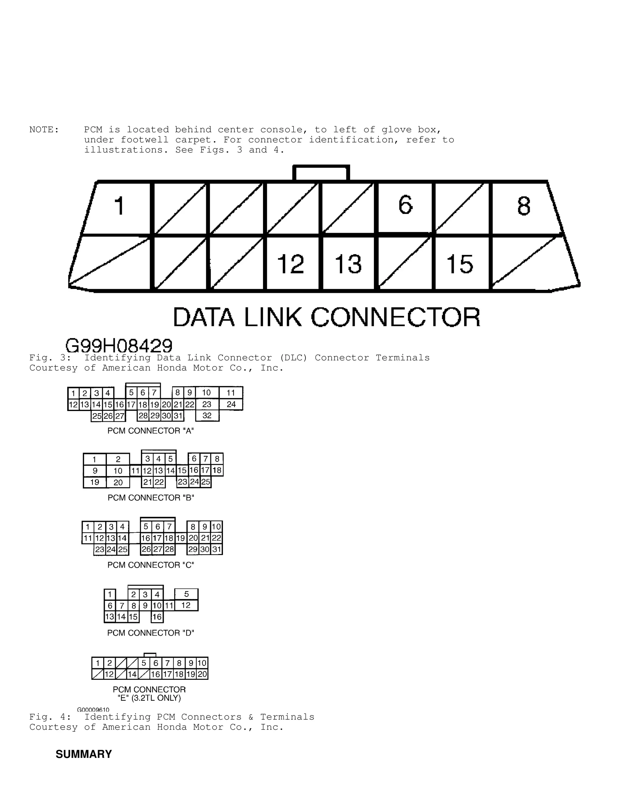


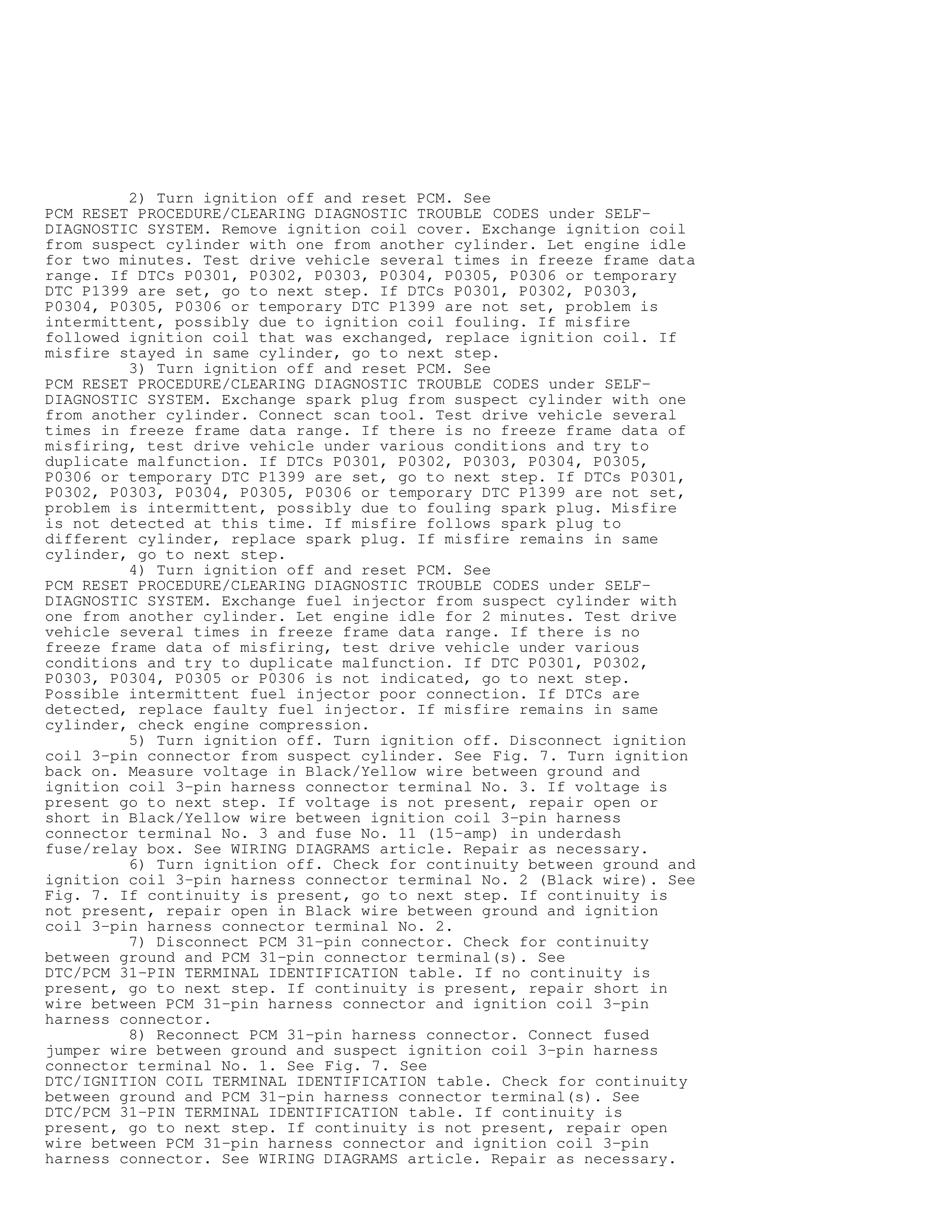
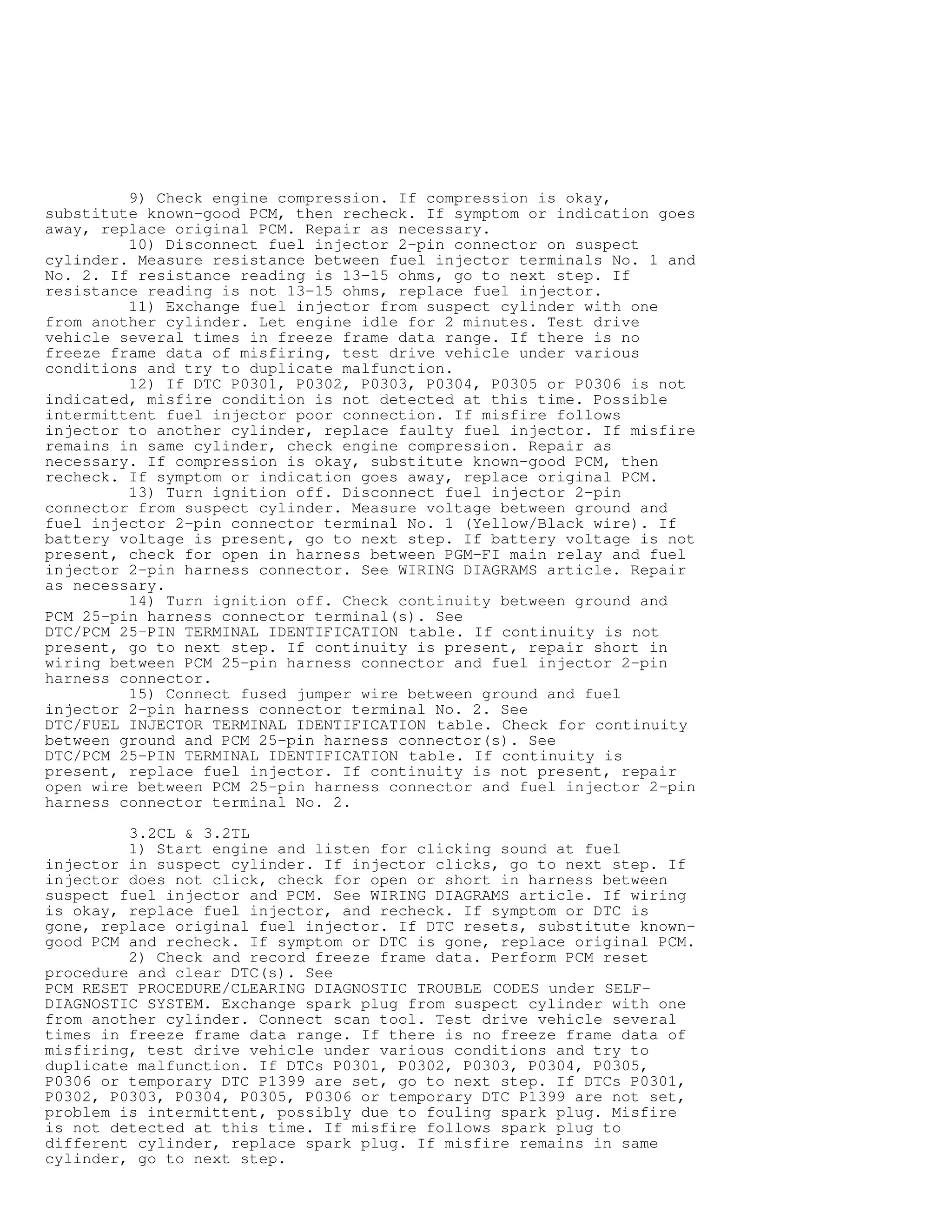

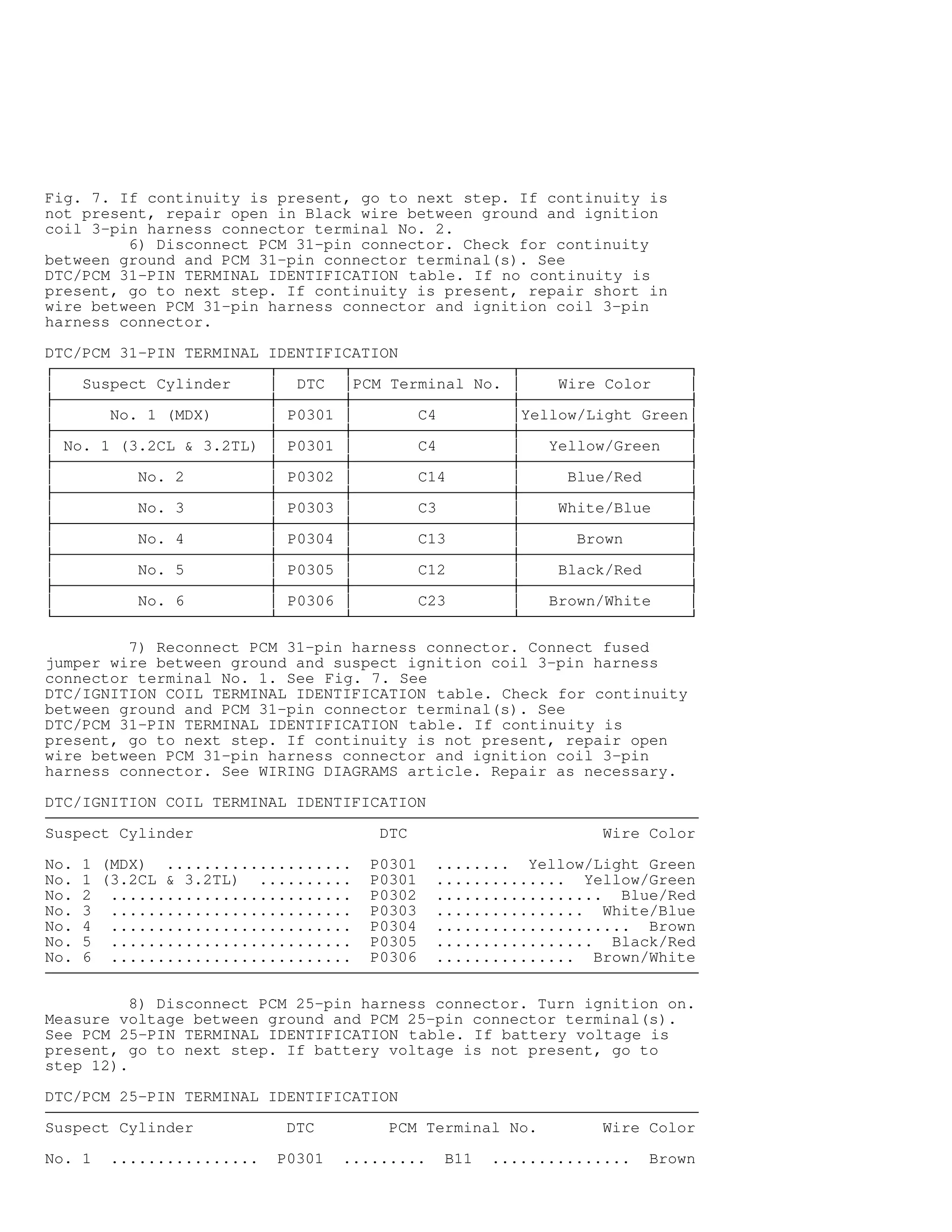


This document provides information on self-diagnostics for 2001 Acura MDX vehicles. It describes how to retrieve diagnostic trouble codes using a scan tool by locating the data link connector under the ash tray. It also explains that if no hard fault codes exist after checking for codes, to proceed to troubleshooting by driveability symptoms or checking for intermittent codes. Freeze frame data from when a fault first occurred can also help with troubleshooting.


![[BPM DAY DF 2012] EMATER, EMBRAPA E SEBRAE – Árvore da Realidade Atual e Mape...](https://cdn.slidesharecdn.com/ss_thumbnails/sebrae-embrapa-emater-151117162649-lva1-app6892-thumbnail.jpg?width=640&height=640&fit=bounds)


![DTC DETECTION LOGIC AND CONDITIONS [SKYACTIV-G 2.0]](https://cdn.slidesharecdn.com/ss_thumbnails/dtcdetectionlogicandconditionsskyactiv-g2-230327073026-3316ee0b-thumbnail.jpg?width=640&height=640&fit=bounds)


