SlideShare a Scribd company logo
1 of 10
Download to read offline
White Paper:QCI-WP003 QuickSilver Controls, Inc.
Date: 14 March 2008 www.QuickSilverControls.com
Property of QuickSilver Controls, Inc. Page 1 of 10 This document is subject to change without notice.
QuickControl® and QCI® are Registered Trademarks of QuickSilver Controls, Inc.
SilverLode™, SilverNugget™, SilverDust™, PVIA™, QuickSilver Controls™, and AntiHunt™ are trademarks of
QuickSilver Controls, Inc..
Servo Control Of A Microstep Motor
This document describes how QuickSilver
provides servo control of a microstep
motor and the resulting advantages.
Simple Explanation
Stepper Drive and Motor
The common stepper motor is more
accurately a 100 pole, 2 phase, AC motor.
A stepper drive steps (or microsteps) the current in the two phases to move the motor to
discrete positions. A stepped sine wave is generated as the drive rotates the motor. The
frequency of the sine wave increases as the speed increases, but the amplitude remains
constant.
Servo Drive And Motor
A common servo motor is more accurately a 4 to
12 pole, 3 phase, AC brushless motor. When
compared to a stepper, the common servo motor
has fewer poles and 3 phases instead of 2. Like
a stepper drive, a servo drive sets the current in
the 3 phases to move the motor to a position.
Unlike a stepper drive, the servo drive generates a variable amplitude sine wave to change
both speed and torque. The servo drive uses feedback from the motor (typically an encoder)
to set the sine wave’s frequency and amplitude (speed and torque respectively). Note, the use
of feedback to continually adjust current is what allows the system to be called a “servo” not
the motor’s construction.
QuickSilver’s Servo
Drive and Motor
QuickSilver combines these
two technologies. QuickSilver
uses a 100 pole, 2 phase, AC
motor (typical stepper). It sets
the current in these 2 phases to
move the motor to a position.
The encoder is used to generate a smooth sine wave of varying frequency and amplitude to
adjust speed and torque respectively.
Note, this is not just adjusting the position (i.e. position maintenance), commonly done by stepper
drives. We have a full 4-quadrant, variable frequency, servo loop that adjusts the current every 120
microseconds. Our technology gives you all the performance of a traditional servo motor at the cost of
a traditional microstep motor. Our motors are physically the same as what the industry calls microstep
motors, but with our patented drive technology, we make servo motors out of them.
PHASE B
PHASE A
OPEN LOOP
STEPPER DRIVER
OPEN LOOP DRIVE
DIRECTION
STEP
STEPPER MOTOR
FIXED WAVEFORM
TORQUE SETTING DEPENDENT
CLOSED LOOP SERVO
STEP MOTOR
2 PHASE
=
PHASE A
PHASE B AC MOTOR
FEEDBACK DEPENDENT
VARIABLE WAVEFORM
PHASE B
PHASE A
PHASE C
3 PHASE AC
SERVO MOTOR
WITH ENCODER
CLOSE LOOP
SERVO DRIVER
CLOSED LOOP SERVO
White Paper:QCI-WP003 QuickSilver Controls, Inc.
QuickSilver Controls, Inc. Page 2 of 10
Detailed Explanation
Stepper Drive and Motor
PHASE B
PHASE A
OPEN LOOP
STEPPER DRIVER
OPEN LOOP DRIVE
DIRECTION
STEP
STEPPER MOTOR
FIXED WAVEFORM
TORQUE SETTING DEPENDENT
The common stepper motor is more accurately a 100 pole, 2 phase, AC motor. A stepper
drive steps (or microsteps) the current in the two phases to move the motor to discrete
positions. A rough sine wave is generated as the drive rotates the motor. The frequency of the
sine wave increases as the commanded speed increases, but the amplitude remains constant.
The permanent magnet in the rotor is attracted to the magnetic field generated by the
windings. To produce torque, the motor requires a following error, as no torque is produced
when the rotor magnet is fully aligned with the stator field. A variation in load torque
requirements causes a variation in the following angle, with braking causing an overshoot if the
motor must supply negative torque (braking). Exceeding the torque capabilities of the motor
may cause the motor to lose steps, change speed, or even change direction! The normal
prevention for these errors involves limiting the use of torque to approximately 1/3 to ½ of the
motor capability as well as careful tailoring of the motion profile. This may be especially difficult
in the presence of varying load and variable system backlash.
The torque produced by this system varies with the following angle between the stator field
and the rotor magnet. Each step change in position of the winding fields results in an impulse
in the driving torque. The amplitude of these impulses is by microstepping, but the impulse
nature remains, imparting acoustical noise to the system. The torque variation with position
error may be approximated a rotary spring; this spring interacts with the rotary inertia of the
system producing strong resonances which may produce ringing and long settling times as
well as frequencies of operation with little effective torque. See the FAQ.
White Paper:QCI-WP003 QuickSilver Controls, Inc.
QuickSilver Controls, Inc. Page 3 of 10
Servo Drive And Motor
PHASE B
PHASE A
PHASE C
AC MOTOR
3 PHASE
SERVOMOTOR
3-PHASE
3-PHASE CLOSED LOOP
A common servo motor is more accurately a 4 to 12 pole, 3 phase, AC or DC brushless motor.
When compared to a stepper, the common servo motor has fewer poles and 3 phases instead
of 2. Like a stepper drive, a servo drive sets the current in the 3 phases to move the motor to
a position. There are three types of drives in common use: AC brushless use sinusoidal
commutation while DC brushless commonly use either a 6 step or 12 step commutation. The
commutation circuits/subroutines of the drive vary the current to the windings as the rotor
moves, keeping the angle between the stator field and the rotor near the optimal point to
produce torque. In the case of the sinusoidal AC brushless controllers, this angle may be
closely regulated, minimizing the torque ripple in the system. The 6 step and 12 step DC
brushless designs, with their larger commutation steps, more closely approximate the discrete
steps in commutation of the DC brush motor with limited commutator segments. The larger
steps result in larger variation in the angle between the stator field and the rotor magnet,
resulting in greater torque ripple.
The most significant differences between the open loop stepper and the servo drive are how
the speed of the drive is determined and how the torque is regulated. The stepper drive varies
the position and speed of the stator field without regard for the rotor position, whereas the
servo motor varies position and speed of the stator field as a direct result of position in the
process of commutation. The torque of the stepper is passively modulated by the variation of
the following error between the stator magnetic field and the rotor, where as the servo requires
a feedback sensor to measure the error between commanded position and actual position,
with the control equation actively varying the strength of the stator field to vary the torque. In
the case of the servo, a sudden change in load requirements may introduce position error, but
not the loss of synchronism between drive and the motor as the drive is made aware of the
motor dynamics by the feedback sensor.
Note: The use of feedback to actively adjust torque by adjusting the winding currents is what
allows the system to be called a “servo”. It is not the construction of the motor.
White Paper:QCI-WP003 QuickSilver Controls, Inc.
QuickSilver Controls, Inc. Page 4 of 10
Unlike a stepper drive, the servo drive generates variable amplitude drive waveform to change
both speed and torque.
QuickSilver’s Servo Drive and Motor
CLOSED LOOP SERVO
STEP MOTOR
2 PHASE
=
PHASE A
PHASE B AC MOTOR
FEEDBACK DEPENDENT
VARIABLE WAVEFORM
QuickSilver combines these two technologies. QuickSilver uses a 100 pole, 2 phase, AC
motor (typical stepper). When operating in closed loop mode, the currents to the two phases
are modulated in a sinusoidal manner with the phase and frequency controlled by the feedback
encoder, and the amplitude controlled by a control law based on the target and actual
trajectories. This mode of operation is in the same manner as was for the three phase AC
brushless servos, with full 4-quadrant (drive and regenerative breaking) capabilities. This is not
just the common “position maintenance” mode with an open loop stepper and an encoder to
adjusting the position of a stepper at the end of travel to after it has lost steps.
QuickSilver takes advantage of the high torque capability available with high pole count motors
designed for use as steppers as well as their low cost made available by the economies of
scale for this motor type. We also take advantage of the ability of these motors to passively
hold position when stopped by automatically switching between closed loop operation and a
monitored open loop operation when stationary. This Anti-Hunt™ capability prevents the
dithering or hunting commonly present in servo systems when stationary. If the error is caused
to exceed the set position error threshold, the system reverts to closed loop until it again
reduces the position error to below the configured limits.
White Paper:QCI-WP003 QuickSilver Controls, Inc.
QuickSilver Controls, Inc. Page 5 of 10
Advantages
Advantages over Servo:
• 2 to 4 Times the Holding Torque in the same size package.
• Superior Torque Up to 1000-2000 RPM.
• 100:1 Inertial Miss-match
o Eliminates Gearheads
• Cost
• Single Cable For Motor and Encoder
• Anti-Hunt™: No Servo Dither
Advantages over Stepper
• Higher Speed
• No low-speed and mid-speed Resonances (see FAQ below)
• 4 Times More Efficient (Typical)
o Less Heating
o Lower Energy Costs
o See FAQ Below
• More Usable Torque
Our motors yield 2 to 4 times the continuous torque of comparably sized traditional servo
motors due to their high pole count. This effect is termed “magnetic gearing” due to the torque
multiplication associated with increased pole counts. The high resulting torque often allows
these motors to directly drive a load without the need of an intervening gearbox leading to the
industry term “High-Torque Direct Drive” motors.
Quicksilver combines the high torque capabilities of the motor with patented motion control and
digital drive techniques, providing direct drive capability for high inertial loads.
These load inertias may be as large as 100 times the motor inertia (100:1 inertia mismatch)
while still providing smooth responsive positioning control. Traditional systems typically cannot
exceed a 10:1 inertial mismatch. This often eliminates gearheads for inertial mismatch
reduction.
QuickSilver’s Technology
Software within the DSP models the motor as well as the driver, eliminating costly offset-and-
noise-prone current sense circuitry. The model controls the on-chip PWM peripherals, directly
controlling the timing of the full bridge drivers to the motor windings. The result is a true all-
digital control system.
This drive technology incorporates a patented “gated anti-phase” methodology which provides
full 4 quadrant control of the motor windings with excellent linearity through zero. The use of
modeling allows predictive control of the motor drivers, minimizing the effects of time lag in the
control loop, allowing very low inductance motors to be used. The low time constant of the
resulting system produces highly dynamic results: 1.8 degree “step motors” operating to
approximately 4000 RPM.
White Paper:QCI-WP003 QuickSilver Controls, Inc.
QuickSilver Controls, Inc. Page 6 of 10
The motor – which most controllers employ as an open loop step motor – is operated as a high
pole-count PM synchronous AC motor. The phase current is sinusoidally commutated as the
motor rotates, with the control loop varying the magnitude of the current and thus the torque to
achieve the desired position. Closed loop control of the motor eliminates low speed
resonances by eliminating their source (see FAQ below), while simultaneously minimizing the
heat produced and maximizing the available torque to the application. The result is faster and
more precise motions for the end user, with enough energy cost savings to provide a rapid ROI
over the apparently less expensive open-loop stepper system.
Motor History
The early history of electric power generation split early into two camps, Alternating current
(AC) and Direct current (DC) by Westinghouse and Edison, respectively. The DC motors could
be operated easily at variable speeds, but required a brush commutator to keep the motor
spinning, while the AC motors (synchronous and induction) tended to operate over a much
narrower speed range, tied to the power line frequency, unless special techniques were used.
The commutator typically consisted of metal segments connected to (typically) the rotor
windings, with the DC power applied through sliding contacts made of carbon, metal, or a mix
of the two. These brushes generated electrical noise, dust, and they required regular
maintenance. These were improved upon by moving the coils to the stator, and providing
chopped waveforms to the coils by means of electronic switches.
A precision DC brush motor has many commutating segments, and thus is able to compensate
for the rotation of the rotor by adjusting the angle of the magnetic field of the rotor with respect
to the stator in many small steps. This helps keep the torque produced steady and reduces
cogging. Each segment produces a step in an approximately sinusoidal commutation
waveform (by changing the paths of the current through the windings in the rotor. Most
Brushless DC motors, on the other hand, use 3 hard switched phases controlled by position
sensors to produce this function. These motors often have specialized windings and magnetic
structures to produce “Trapezoidal” waveforms to minimize the toque ripple as these motors
rotate. Special care is needed to precisely locate the commutating point for these units as even
a small phase error may produce a significant pulsating torquei
. DC Brushless motors with
approximately sinusoidal Back EMF waveforms driven with trapezoidal waveforms also
produce significant toque ripple in their operation.
The variable speed control of the AC motors came from a different starting point. Commonly
three phase motors were used with variable speed drives which produced a variable speed
variable amplitude 3 phase sine waves to operate these motors at the desired speed. This
process has been applied to both synchronous and induction AC motors. These motors are
typically wound for sinusoidal back EMF.
The AC servo motor, also called a Brushless AC servo motor grows out of this second branch,
using sinusoidal drive signals with sinusoidal back EMF motors. The speed and amplitude of
the sine waves is based on the desired torque as well as the motor type. For AC synchronous
motors, the frequency and phase are locked to the speed and position of the rotor with respect
to the stator. The control of the AC induction motors also involves controlling the rate of slip
between the rotor and the stator to control the rotor currents and thus the torque produced by
the interaction of the rotor magnetic field with the stator field. The advantage of the AC servos
is that by making use of continuously varying sine waves rather than discontinuous trapezoidal
White Paper:QCI-WP003 QuickSilver Controls, Inc.
QuickSilver Controls, Inc. Page 7 of 10
waveforms, smoother operation may be obtained, even in the face of slight phasing errors. The
disadvantage is that the accurate generation of multiple sine waveforms is not a simple task.
Where as the DC brushless driver could use a relatively simple switched inverter with DC
current sensing in the ground leg to set the wanted average DC current through the motor, the
AC drive must generate a sine wave through each winding, requiring multiple control loops and
multiple current sensors (or estimators).
The bipolar stepper motor is a high pole count synchronous AC motor. The speed of a
synchronous motor is proportional to the line frequency and inversely proportional to the
number of poles. That is, a synchronous motor moves forward one pole pair for each 360
electrical degrees of the applied sine wave. A stepper motor, having commonly 100 poles (50
pairs), produces a reduced speed of operation. This effect is often referred to as magnetic
gearing. This high pole count has the same effect as physical gears in that the speed is
reduced and the torque is increased from the motor in proportion to the number of poles.
High pole count AC synchronous motors were first produced to run from line frequency to
provide a low speed/high torque motion without gears. Other engineers noticed that these
same motors could be operated at variable speeds down to zero by switching the current
through the phases, which was very useful for controlling machine tools. The stepper motor
was “born.”
These motors, due to their high pole count, have very high torque constants. Their use in open
loop positioning, however, also requires a steep torque vs. position characteristic so as to have
the motor come to rest over a narrow angle range even in the presence of friction and load.
The high pole count helps here as well. With their typical sinusoidal torque constant repeating
every two poles, the higher the pole count, the smaller the mechanical angle corresponding to
a full electrical cycle. Thus for a given motor size, not only does the torque scale up roughly
proportional to the pole count, but so does the number of electrical cycles. This means that
quadrupling the number of poles makes for some four time the torque with the electrical cycle
increment in one quarter of the mechanical angle. The maximum slope of such a sine wave
shaped torque curve is sixteen times as steep. In comparing a 6 pole motor to a 100 pole (1.8
degree) stepper, these combined effects results in a torque slope factor which is some 278
times as steep. This characteristic high stiffness has allowed the use of stepper motors in high
accuracy open loop operation.
Their extensive incorporation into open loop designs has led to their production in large
quantities leading to optimized tooling with the benefits of quantity of scale: High Quality and
Low Price. The desire to make these motors perform smoother motions has led to motors
optimized for “micro-stepping” - that is having a good sinusoidal torque constant and low
detent torque characteristics.
It is these same motor characteristics that improved the open loop “stepper-motor” operation,
namely high torque constant, high torque to inertia ratio, sinusoidal per-phase torque
constants, and low cogging torque, that are equally useful to closed loop servo control of these
high pole count, poly-phase AC synchronous motors.
The use of Permanent Magnet AC Servo Motors is increasing due to the higher efficiency
compared to induction motors with a more comparable price than past years due to the
increased cost of copper and the reduced cost of magnets.
White Paper:QCI-WP003 QuickSilver Controls, Inc.
QuickSilver Controls, Inc. Page 8 of 10
Frequently Asked Questions
What Makes It A “Servo”?
The Merriam-Webster Dictionaryii
defines a servomechanism as “an automatic device for
controlling large amounts of power by means of very small amounts of power and
automatically correcting the performance of a mechanism.”
One of the earlier known servoiii
(from Latin Servus slave) systems dates back to
approximately 270BC and was a regulator for the water level used by the water clocks of the
day to help them keep more accurate time by keeping the water level constant, and thereby
the water pressure exiting the tank constant. The water passed through a fixed size orifice and
filled a fixed volume before it dumped and refilled. Each dumping of the volume represented
one “tick” of the clock. The water level regulator worked similarly to the float mechanism used
in current day toilet tanks. In this case, the feedback is in the form of the level of the float, and
the difference in level from the desired level operates a valve so as to keep the water level
within the desired range.
Servo motion control systems use position and/or velocity sensors to measure the difference
between the desired and actual operation of the actuator. Amplifiers (electronic, mechanical,
hydraulic, magnetic, etc.) are used to increase the power of the error signal and to affect the
operation of the actuator so as to make the actuator perform the desired motion. The
SilverLode™ system uses optical incremental encoders to measure the motor rotary position,
digital signal processors to process it, and drive electronics to provide the power drive to the
motor to effect the motion.
But Do Not Stepper Motors Have Resonance Problems?
Stepper motor resonance arises in open loop operation due to the steep torque vs. position
error characteristics of an open loop stepper operating in the vicinity of the zero error angle.
When disturbed from this zero error angle (or that angle is suddenly changed, such as by
changing the currents through the windings as happens when the motor is “stepped”), the rotor
of the motor operates as a rotary pendulum, the resulting torque of the motor causing the rotor
to accelerate towards and then pass by the equilibrium point, only to then slow and reverse
again with a slightly lower amplitude due to losses, repeating until the rotor finally comes to
rest at the (new) equilibrium point. If the motor is pulsed near the resonance frequency, the
pendulum effect will cause the amplitude of this oscillation to continue to grow until the rotor is
more than 2 full steps away from the original equilibrium point. At this point the nearest new
equilibrium point is now 4 steps (one full electrical cycle) away from the old equilibrium point,
and the generated torque will cause the rotor to accelerate toward that point. The motor has
lost synchronization with the applied waveform and thus “lost” steps. According to the speed of
operation, the motor may stall, may operate erratically, or may even change speed and
direction!
What Causes The Low Speed Resonance In A Stepmotor?
The low speed resonance of the open loop step motor is a result of the motor operating as a
spring-mass system about its equilibrium point. The motor torque is approximately a sinusoidal
White Paper:QCI-WP003 QuickSilver Controls, Inc.
QuickSilver Controls, Inc. Page 9 of 10
function of its position error. This “spring” interacts with the rotary inertia of the motor to form,
in essence, a rotary pendulum. As the motor is stepped (or microstepped) the equilibrium point
is moved, causing the “pendulum” to seek the new equilibrium point. If the stepping rate
approaches the natural frequency of this “pendulum”, the amplitude of the swinging increases,
often causing the motor to lose synchronization with its drive signals.
When this same motor is operated as an AC servo motor, the commutation keeps the
magnetic field positioned so as to produce the maximum torque for the commanded current
magnitude. A perturbation of the rotor angle results in the magnetic field shifting rather than the
torque changing. Without the position dependent torque term, the spring effect is eliminated as
well as the associated low speed resonance problem.
But Don’t Stepper Motors Run Hot?
A side benefit of operating the motor at the optimal torque angle is that only the current needed
to produce the torque actually needed is applied to the motor. There is not a need to supply full
current unless the peak torque is being utilized. Given that the “rule of thumb” for operation of
a stepper motor is to only use approximately 30% to 50% of the available torque, that same
motor operated as a servo in the same application requires only 30% to 50% current. The main
heating in the windings is P=I2
R, thus at 50% current, the heating is only 25% as compared to
the open loop stepper, while at 30% utilization the heating is only 9%! The result is that the
same “stepper motor”, when used as a servo may be operated quieter, smoother, and cooler,
and with higher available torque while running over a wider range of speeds. And these
improvements are available while at the same time avoiding the low speed resonance effects
of the open loop stepper.
But How Can The Motor Draw 2 Amps When The 48v Power
Supply Is Only Supplying 160 Ma?
The driver and controller form what is effectively as step-down switching power supply. The
power into the Controller, minus the relatively low losses of the driver and the power to the
DSP and other electronics, produces the mechanical output power from the motor plus motor
heating. When the motor is stopped, there is no mechanical output power (P=speed * Torque),
and thus the power into the motor is all heating. In the case of a motor with a 1.2 ohm winding,
this is on the order 4.8W, and would account for approximately 100mA at 48v. Additional input
power is required for the electronics including the losses in the drivers; in the given example
this would account for the other 60mA of supply current. The low current usage only lasts while
the motor is not providing mechanical work. As the motor spins faster and/or the torque
increases, the mechanical output power increases. This additional power must be supplied
from the power supply, and the input current goes up.
What Is Anti-Hunt™?
Just because the motor can be operated as a high performance servo system does not mean
that it can not be switched back to its humble open loop beginning. When the motor is
sufficiently close to the desired position, the operating mode of the motor can be switched to
open loop operation at a user defined current level. With the servo loop turned off, the hunting
or dithering of the servo loop is eliminated. If the motor position is disturbed or another motion
is requested, the servo operation is then restored. This allows for rapid motions with quick
settling as afforded by the servo control while still retaining the ability to stop solidly without
White Paper:QCI-WP003 QuickSilver Controls, Inc.
QuickSilver Controls, Inc. Page 10 of 10
dithering. This eliminates acoustical noise and movement that would affect applications such
as imaging. The ability to eliminate dithering when stopped also reduces wear on any attached
lead screws or gears that the continual hunting of a servo may cause even when there is no
motion commanded, often extending the life of the attached mechanism.
i
http://www.ornl.gov/~webworks/cpr/pres/107923_.pdf
ii
www.merriam.com
iii
originally http://www.control-systems.net/recursos/articulos/002.htm, no longer posted, but may be available on
www.archive.org

More Related Content

What's hot

What's hot (20)

Stepper Motor Types, Advantages And Applications
 Stepper Motor Types, Advantages And Applications Stepper Motor Types, Advantages And Applications
Stepper Motor Types, Advantages And Applications
 
Stepper motors
Stepper motorsStepper motors
Stepper motors
 
Stepper motor Presentation
Stepper motor Presentation Stepper motor Presentation
Stepper motor Presentation
 
slide on stepper motor
slide on stepper motorslide on stepper motor
slide on stepper motor
 
Stepper motors
Stepper motorsStepper motors
Stepper motors
 
Setpper Motor
 Setpper Motor Setpper Motor
Setpper Motor
 
Stepper motor
Stepper motorStepper motor
Stepper motor
 
Servo selection
Servo selectionServo selection
Servo selection
 
Understanding Common Servo Motors
Understanding Common Servo MotorsUnderstanding Common Servo Motors
Understanding Common Servo Motors
 
Ac servomotor
Ac servomotorAc servomotor
Ac servomotor
 
Stepper motors
Stepper motorsStepper motors
Stepper motors
 
Unit 2 servo motor
Unit 2 servo motorUnit 2 servo motor
Unit 2 servo motor
 
Electric Servo Motor
Electric Servo MotorElectric Servo Motor
Electric Servo Motor
 
Stepper motor
Stepper motorStepper motor
Stepper motor
 
Seminar on stepper motor
Seminar on stepper motorSeminar on stepper motor
Seminar on stepper motor
 
Servo motor and servo drive
Servo motor and servo driveServo motor and servo drive
Servo motor and servo drive
 
Stepper motor site
Stepper motor siteStepper motor site
Stepper motor site
 
Motors and controller circuit
Motors and controller circuitMotors and controller circuit
Motors and controller circuit
 
Stepper motor
Stepper motorStepper motor
Stepper motor
 
Unit 3 steppermotors
Unit 3 steppermotorsUnit 3 steppermotors
Unit 3 steppermotors
 

Similar to QuickSilver Controls QCI-WP003

It 5170 stepper motor
It 5170 stepper motorIt 5170 stepper motor
It 5170 stepper motorIshfaqah
 
Vector Speed Control of Induction Motor
Vector Speed Control of Induction MotorVector Speed Control of Induction Motor
Vector Speed Control of Induction MotorRanjith Samala
 
More About Stepper Motors
More About Stepper MotorsMore About Stepper Motors
More About Stepper Motorsiratepaddle343
 
Special motors
Special motorsSpecial motors
Special motorsmadhu1729
 
three phase induction motor drive
three phase induction motor drivethree phase induction motor drive
three phase induction motor driveRatnesh Verma
 
Understanding Electric Motors
Understanding Electric MotorsUnderstanding Electric Motors
Understanding Electric Motorsiratepaddle343
 
Understanding Electric Motors
Understanding Electric MotorsUnderstanding Electric Motors
Understanding Electric Motorsabusivelexicon144
 
Introduction to motors
Introduction to motorsIntroduction to motors
Introduction to motorskhairee khalid
 
Introduction to AC Motors with constructional details.ppt
Introduction to AC Motors with constructional details.pptIntroduction to AC Motors with constructional details.ppt
Introduction to AC Motors with constructional details.pptdatamboli
 
Speed Control of BLDC Motor with Four Quadrant Operation Using dsPIC
Speed Control of BLDC Motor with Four Quadrant Operation Using dsPICSpeed Control of BLDC Motor with Four Quadrant Operation Using dsPIC
Speed Control of BLDC Motor with Four Quadrant Operation Using dsPICijsrd.com
 

Similar to QuickSilver Controls QCI-WP003 (20)

Actuators.pptx
Actuators.pptxActuators.pptx
Actuators.pptx
 
Stepper motor
Stepper motorStepper motor
Stepper motor
 
It 5170 stepper motor
It 5170 stepper motorIt 5170 stepper motor
It 5170 stepper motor
 
stepper motor
stepper motorstepper motor
stepper motor
 
Vector Speed Control of Induction Motor
Vector Speed Control of Induction MotorVector Speed Control of Induction Motor
Vector Speed Control of Induction Motor
 
More About Stepper Motors
More About Stepper MotorsMore About Stepper Motors
More About Stepper Motors
 
Servo motor drive
Servo motor driveServo motor drive
Servo motor drive
 
Special motors
Special motorsSpecial motors
Special motors
 
More About Stepper Motors
More About Stepper MotorsMore About Stepper Motors
More About Stepper Motors
 
three phase induction motor drive
three phase induction motor drivethree phase induction motor drive
three phase induction motor drive
 
Motors
MotorsMotors
Motors
 
Understanding Electric Motors
Understanding Electric MotorsUnderstanding Electric Motors
Understanding Electric Motors
 
Understanding Electric Motors
Understanding Electric MotorsUnderstanding Electric Motors
Understanding Electric Motors
 
Motor
MotorMotor
Motor
 
Sprabq8
Sprabq8Sprabq8
Sprabq8
 
Introduction to motors
Introduction to motorsIntroduction to motors
Introduction to motors
 
Introduction to AC Motors with constructional details.ppt
Introduction to AC Motors with constructional details.pptIntroduction to AC Motors with constructional details.ppt
Introduction to AC Motors with constructional details.ppt
 
Speed Control of BLDC Motor with Four Quadrant Operation Using dsPIC
Speed Control of BLDC Motor with Four Quadrant Operation Using dsPICSpeed Control of BLDC Motor with Four Quadrant Operation Using dsPIC
Speed Control of BLDC Motor with Four Quadrant Operation Using dsPIC
 
Slide 1.pptx
Slide 1.pptxSlide 1.pptx
Slide 1.pptx
 
More About Stepper Motors
More About Stepper MotorsMore About Stepper Motors
More About Stepper Motors
 

More from Electromate

Automated screw thread quality checking using SMAC LAR55 actuator new produc...
Automated screw thread quality checking using SMAC LAR55 actuator  new produc...Automated screw thread quality checking using SMAC LAR55 actuator  new produc...
Automated screw thread quality checking using SMAC LAR55 actuator new produc...Electromate
 
An overview of the various kinematic models in both parallel and serial robot...
An overview of the various kinematic models in both parallel and serial robot...An overview of the various kinematic models in both parallel and serial robot...
An overview of the various kinematic models in both parallel and serial robot...Electromate
 
Galil motion control robotic symposium presentation-linear motion from non-li...
Galil motion control robotic symposium presentation-linear motion from non-li...Galil motion control robotic symposium presentation-linear motion from non-li...
Galil motion control robotic symposium presentation-linear motion from non-li...Electromate
 
Advanced motion controls robotics symposium presentation-open standard tools ...
Advanced motion controls robotics symposium presentation-open standard tools ...Advanced motion controls robotics symposium presentation-open standard tools ...
Advanced motion controls robotics symposium presentation-open standard tools ...Electromate
 
Maxon motor ag robotic symposium presentation-impedance control overview and ...
Maxon motor ag robotic symposium presentation-impedance control overview and ...Maxon motor ag robotic symposium presentation-impedance control overview and ...
Maxon motor ag robotic symposium presentation-impedance control overview and ...Electromate
 
Kollmorgen robotic symposium presentation-motor design impacts on the optimiz...
Kollmorgen robotic symposium presentation-motor design impacts on the optimiz...Kollmorgen robotic symposium presentation-motor design impacts on the optimiz...
Kollmorgen robotic symposium presentation-motor design impacts on the optimiz...Electromate
 
Harmonic drive llc robotics symposium presentation-designing from the inside ...
Harmonic drive llc robotics symposium presentation-designing from the inside ...Harmonic drive llc robotics symposium presentation-designing from the inside ...
Harmonic drive llc robotics symposium presentation-designing from the inside ...Electromate
 
Thomson Linear Dual Shaft Rail 2DA Modular Specs
Thomson Linear Dual Shaft Rail 2DA Modular SpecsThomson Linear Dual Shaft Rail 2DA Modular Specs
Thomson Linear Dual Shaft Rail 2DA Modular SpecsElectromate
 
Thomson Linear 2DA QuickSlide System with Brake
Thomson Linear 2DA QuickSlide System with BrakeThomson Linear 2DA QuickSlide System with Brake
Thomson Linear 2DA QuickSlide System with BrakeElectromate
 
Thomson Linear RoundRail 2CA Web Universal Carriage Specs
Thomson Linear RoundRail 2CA Web Universal Carriage SpecsThomson Linear RoundRail 2CA Web Universal Carriage Specs
Thomson Linear RoundRail 2CA Web Universal Carriage SpecsElectromate
 
Thomson Linear RoundRail 1VC Double End Supported Specs
Thomson Linear RoundRail 1VC Double End Supported SpecsThomson Linear RoundRail 1VC Double End Supported Specs
Thomson Linear RoundRail 1VC Double End Supported SpecsElectromate
 
Thomson Linear RoundRail 2CA Web Flanged Carriage Specs
Thomson Linear RoundRail 2CA Web Flanged Carriage SpecsThomson Linear RoundRail 2CA Web Flanged Carriage Specs
Thomson Linear RoundRail 2CA Web Flanged Carriage SpecsElectromate
 
Thomson Linear RoundRail Twin Shaft Web 2CA
Thomson Linear RoundRail Twin Shaft Web 2CAThomson Linear RoundRail Twin Shaft Web 2CA
Thomson Linear RoundRail Twin Shaft Web 2CAElectromate
 
Thomson Linear RoundRail 1VC Double Unsupported Specs
Thomson Linear RoundRail 1VC Double Unsupported SpecsThomson Linear RoundRail 1VC Double Unsupported Specs
Thomson Linear RoundRail 1VC Double Unsupported SpecsElectromate
 
Thomson Linear WhisperTrak Actuators
Thomson Linear WhisperTrak ActuatorsThomson Linear WhisperTrak Actuators
Thomson Linear WhisperTrak ActuatorsElectromate
 
Thomson T-Series Profile Rail
Thomson T-Series Profile RailThomson T-Series Profile Rail
Thomson T-Series Profile RailElectromate
 
Thomson Linear RoundRail Accessories Collapsable Bellows Specs
Thomson Linear RoundRail Accessories Collapsable Bellows SpecsThomson Linear RoundRail Accessories Collapsable Bellows Specs
Thomson Linear RoundRail Accessories Collapsable Bellows SpecsElectromate
 
Thomson Linear Roundrail Dual Shaft Rail 2DA Specs
Thomson Linear Roundrail Dual Shaft Rail 2DA SpecsThomson Linear Roundrail Dual Shaft Rail 2DA Specs
Thomson Linear Roundrail Dual Shaft Rail 2DA SpecsElectromate
 
Thomson Linear RoundRail Continuous Support 1PC Specs
Thomson Linear RoundRail Continuous Support 1PC SpecsThomson Linear RoundRail Continuous Support 1PC Specs
Thomson Linear RoundRail Continuous Support 1PC SpecsElectromate
 
Thomson Linear RoundRail Continuous Support 1PB Specs
Thomson Linear RoundRail Continuous Support 1PB SpecsThomson Linear RoundRail Continuous Support 1PB Specs
Thomson Linear RoundRail Continuous Support 1PB SpecsElectromate
 

More from Electromate (20)

Automated screw thread quality checking using SMAC LAR55 actuator new produc...
Automated screw thread quality checking using SMAC LAR55 actuator  new produc...Automated screw thread quality checking using SMAC LAR55 actuator  new produc...
Automated screw thread quality checking using SMAC LAR55 actuator new produc...
 
An overview of the various kinematic models in both parallel and serial robot...
An overview of the various kinematic models in both parallel and serial robot...An overview of the various kinematic models in both parallel and serial robot...
An overview of the various kinematic models in both parallel and serial robot...
 
Galil motion control robotic symposium presentation-linear motion from non-li...
Galil motion control robotic symposium presentation-linear motion from non-li...Galil motion control robotic symposium presentation-linear motion from non-li...
Galil motion control robotic symposium presentation-linear motion from non-li...
 
Advanced motion controls robotics symposium presentation-open standard tools ...
Advanced motion controls robotics symposium presentation-open standard tools ...Advanced motion controls robotics symposium presentation-open standard tools ...
Advanced motion controls robotics symposium presentation-open standard tools ...
 
Maxon motor ag robotic symposium presentation-impedance control overview and ...
Maxon motor ag robotic symposium presentation-impedance control overview and ...Maxon motor ag robotic symposium presentation-impedance control overview and ...
Maxon motor ag robotic symposium presentation-impedance control overview and ...
 
Kollmorgen robotic symposium presentation-motor design impacts on the optimiz...
Kollmorgen robotic symposium presentation-motor design impacts on the optimiz...Kollmorgen robotic symposium presentation-motor design impacts on the optimiz...
Kollmorgen robotic symposium presentation-motor design impacts on the optimiz...
 
Harmonic drive llc robotics symposium presentation-designing from the inside ...
Harmonic drive llc robotics symposium presentation-designing from the inside ...Harmonic drive llc robotics symposium presentation-designing from the inside ...
Harmonic drive llc robotics symposium presentation-designing from the inside ...
 
Thomson Linear Dual Shaft Rail 2DA Modular Specs
Thomson Linear Dual Shaft Rail 2DA Modular SpecsThomson Linear Dual Shaft Rail 2DA Modular Specs
Thomson Linear Dual Shaft Rail 2DA Modular Specs
 
Thomson Linear 2DA QuickSlide System with Brake
Thomson Linear 2DA QuickSlide System with BrakeThomson Linear 2DA QuickSlide System with Brake
Thomson Linear 2DA QuickSlide System with Brake
 
Thomson Linear RoundRail 2CA Web Universal Carriage Specs
Thomson Linear RoundRail 2CA Web Universal Carriage SpecsThomson Linear RoundRail 2CA Web Universal Carriage Specs
Thomson Linear RoundRail 2CA Web Universal Carriage Specs
 
Thomson Linear RoundRail 1VC Double End Supported Specs
Thomson Linear RoundRail 1VC Double End Supported SpecsThomson Linear RoundRail 1VC Double End Supported Specs
Thomson Linear RoundRail 1VC Double End Supported Specs
 
Thomson Linear RoundRail 2CA Web Flanged Carriage Specs
Thomson Linear RoundRail 2CA Web Flanged Carriage SpecsThomson Linear RoundRail 2CA Web Flanged Carriage Specs
Thomson Linear RoundRail 2CA Web Flanged Carriage Specs
 
Thomson Linear RoundRail Twin Shaft Web 2CA
Thomson Linear RoundRail Twin Shaft Web 2CAThomson Linear RoundRail Twin Shaft Web 2CA
Thomson Linear RoundRail Twin Shaft Web 2CA
 
Thomson Linear RoundRail 1VC Double Unsupported Specs
Thomson Linear RoundRail 1VC Double Unsupported SpecsThomson Linear RoundRail 1VC Double Unsupported Specs
Thomson Linear RoundRail 1VC Double Unsupported Specs
 
Thomson Linear WhisperTrak Actuators
Thomson Linear WhisperTrak ActuatorsThomson Linear WhisperTrak Actuators
Thomson Linear WhisperTrak Actuators
 
Thomson T-Series Profile Rail
Thomson T-Series Profile RailThomson T-Series Profile Rail
Thomson T-Series Profile Rail
 
Thomson Linear RoundRail Accessories Collapsable Bellows Specs
Thomson Linear RoundRail Accessories Collapsable Bellows SpecsThomson Linear RoundRail Accessories Collapsable Bellows Specs
Thomson Linear RoundRail Accessories Collapsable Bellows Specs
 
Thomson Linear Roundrail Dual Shaft Rail 2DA Specs
Thomson Linear Roundrail Dual Shaft Rail 2DA SpecsThomson Linear Roundrail Dual Shaft Rail 2DA Specs
Thomson Linear Roundrail Dual Shaft Rail 2DA Specs
 
Thomson Linear RoundRail Continuous Support 1PC Specs
Thomson Linear RoundRail Continuous Support 1PC SpecsThomson Linear RoundRail Continuous Support 1PC Specs
Thomson Linear RoundRail Continuous Support 1PC Specs
 
Thomson Linear RoundRail Continuous Support 1PB Specs
Thomson Linear RoundRail Continuous Support 1PB SpecsThomson Linear RoundRail Continuous Support 1PB Specs
Thomson Linear RoundRail Continuous Support 1PB Specs
 

Recently uploaded

Transcript: New from BookNet Canada for 2024: BNC BiblioShare - Tech Forum 2024
Transcript: New from BookNet Canada for 2024: BNC BiblioShare - Tech Forum 2024Transcript: New from BookNet Canada for 2024: BNC BiblioShare - Tech Forum 2024
Transcript: New from BookNet Canada for 2024: BNC BiblioShare - Tech Forum 2024BookNet Canada
 
Tech-Forward - Achieving Business Readiness For Copilot in Microsoft 365
Tech-Forward - Achieving Business Readiness For Copilot in Microsoft 365Tech-Forward - Achieving Business Readiness For Copilot in Microsoft 365
Tech-Forward - Achieving Business Readiness For Copilot in Microsoft 3652toLead Limited
 
CloudStudio User manual (basic edition):
CloudStudio User manual (basic edition):CloudStudio User manual (basic edition):
CloudStudio User manual (basic edition):comworks
 
Install Stable Diffusion in windows machine
Install Stable Diffusion in windows machineInstall Stable Diffusion in windows machine
Install Stable Diffusion in windows machinePadma Pradeep
 
Build your next Gen AI Breakthrough - April 2024
Build your next Gen AI Breakthrough - April 2024Build your next Gen AI Breakthrough - April 2024
Build your next Gen AI Breakthrough - April 2024Neo4j
 
Swan(sea) Song – personal research during my six years at Swansea ... and bey...
Swan(sea) Song – personal research during my six years at Swansea ... and bey...Swan(sea) Song – personal research during my six years at Swansea ... and bey...
Swan(sea) Song – personal research during my six years at Swansea ... and bey...Alan Dix
 
Benefits Of Flutter Compared To Other Frameworks
Benefits Of Flutter Compared To Other FrameworksBenefits Of Flutter Compared To Other Frameworks
Benefits Of Flutter Compared To Other FrameworksSoftradix Technologies
 
#StandardsGoals for 2024: What’s new for BISAC - Tech Forum 2024
#StandardsGoals for 2024: What’s new for BISAC - Tech Forum 2024#StandardsGoals for 2024: What’s new for BISAC - Tech Forum 2024
#StandardsGoals for 2024: What’s new for BISAC - Tech Forum 2024BookNet Canada
 
New from BookNet Canada for 2024: BNC BiblioShare - Tech Forum 2024
New from BookNet Canada for 2024: BNC BiblioShare - Tech Forum 2024New from BookNet Canada for 2024: BNC BiblioShare - Tech Forum 2024
New from BookNet Canada for 2024: BNC BiblioShare - Tech Forum 2024BookNet Canada
 
Designing IA for AI - Information Architecture Conference 2024
Designing IA for AI - Information Architecture Conference 2024Designing IA for AI - Information Architecture Conference 2024
Designing IA for AI - Information Architecture Conference 2024Enterprise Knowledge
 
How to convert PDF to text with Nanonets
How to convert PDF to text with NanonetsHow to convert PDF to text with Nanonets
How to convert PDF to text with Nanonetsnaman860154
 
"Federated learning: out of reach no matter how close",Oleksandr Lapshyn
"Federated learning: out of reach no matter how close",Oleksandr Lapshyn"Federated learning: out of reach no matter how close",Oleksandr Lapshyn
"Federated learning: out of reach no matter how close",Oleksandr LapshynFwdays
 
Injustice - Developers Among Us (SciFiDevCon 2024)
Injustice - Developers Among Us (SciFiDevCon 2024)Injustice - Developers Among Us (SciFiDevCon 2024)
Injustice - Developers Among Us (SciFiDevCon 2024)Allon Mureinik
 
Understanding the Laravel MVC Architecture
Understanding the Laravel MVC ArchitectureUnderstanding the Laravel MVC Architecture
Understanding the Laravel MVC ArchitecturePixlogix Infotech
 
Breaking the Kubernetes Kill Chain: Host Path Mount
Breaking the Kubernetes Kill Chain: Host Path MountBreaking the Kubernetes Kill Chain: Host Path Mount
Breaking the Kubernetes Kill Chain: Host Path MountPuma Security, LLC
 
My Hashitalk Indonesia April 2024 Presentation
My Hashitalk Indonesia April 2024 PresentationMy Hashitalk Indonesia April 2024 Presentation
My Hashitalk Indonesia April 2024 PresentationRidwan Fadjar
 
Artificial intelligence in the post-deep learning era
Artificial intelligence in the post-deep learning eraArtificial intelligence in the post-deep learning era
Artificial intelligence in the post-deep learning eraDeakin University
 

Recently uploaded (20)

Transcript: New from BookNet Canada for 2024: BNC BiblioShare - Tech Forum 2024
Transcript: New from BookNet Canada for 2024: BNC BiblioShare - Tech Forum 2024Transcript: New from BookNet Canada for 2024: BNC BiblioShare - Tech Forum 2024
Transcript: New from BookNet Canada for 2024: BNC BiblioShare - Tech Forum 2024
 
E-Vehicle_Hacking_by_Parul Sharma_null_owasp.pptx
E-Vehicle_Hacking_by_Parul Sharma_null_owasp.pptxE-Vehicle_Hacking_by_Parul Sharma_null_owasp.pptx
E-Vehicle_Hacking_by_Parul Sharma_null_owasp.pptx
 
Tech-Forward - Achieving Business Readiness For Copilot in Microsoft 365
Tech-Forward - Achieving Business Readiness For Copilot in Microsoft 365Tech-Forward - Achieving Business Readiness For Copilot in Microsoft 365
Tech-Forward - Achieving Business Readiness For Copilot in Microsoft 365
 
CloudStudio User manual (basic edition):
CloudStudio User manual (basic edition):CloudStudio User manual (basic edition):
CloudStudio User manual (basic edition):
 
Install Stable Diffusion in windows machine
Install Stable Diffusion in windows machineInstall Stable Diffusion in windows machine
Install Stable Diffusion in windows machine
 
Build your next Gen AI Breakthrough - April 2024
Build your next Gen AI Breakthrough - April 2024Build your next Gen AI Breakthrough - April 2024
Build your next Gen AI Breakthrough - April 2024
 
Swan(sea) Song – personal research during my six years at Swansea ... and bey...
Swan(sea) Song – personal research during my six years at Swansea ... and bey...Swan(sea) Song – personal research during my six years at Swansea ... and bey...
Swan(sea) Song – personal research during my six years at Swansea ... and bey...
 
Benefits Of Flutter Compared To Other Frameworks
Benefits Of Flutter Compared To Other FrameworksBenefits Of Flutter Compared To Other Frameworks
Benefits Of Flutter Compared To Other Frameworks
 
#StandardsGoals for 2024: What’s new for BISAC - Tech Forum 2024
#StandardsGoals for 2024: What’s new for BISAC - Tech Forum 2024#StandardsGoals for 2024: What’s new for BISAC - Tech Forum 2024
#StandardsGoals for 2024: What’s new for BISAC - Tech Forum 2024
 
New from BookNet Canada for 2024: BNC BiblioShare - Tech Forum 2024
New from BookNet Canada for 2024: BNC BiblioShare - Tech Forum 2024New from BookNet Canada for 2024: BNC BiblioShare - Tech Forum 2024
New from BookNet Canada for 2024: BNC BiblioShare - Tech Forum 2024
 
Designing IA for AI - Information Architecture Conference 2024
Designing IA for AI - Information Architecture Conference 2024Designing IA for AI - Information Architecture Conference 2024
Designing IA for AI - Information Architecture Conference 2024
 
How to convert PDF to text with Nanonets
How to convert PDF to text with NanonetsHow to convert PDF to text with Nanonets
How to convert PDF to text with Nanonets
 
"Federated learning: out of reach no matter how close",Oleksandr Lapshyn
"Federated learning: out of reach no matter how close",Oleksandr Lapshyn"Federated learning: out of reach no matter how close",Oleksandr Lapshyn
"Federated learning: out of reach no matter how close",Oleksandr Lapshyn
 
DMCC Future of Trade Web3 - Special Edition
DMCC Future of Trade Web3 - Special EditionDMCC Future of Trade Web3 - Special Edition
DMCC Future of Trade Web3 - Special Edition
 
Injustice - Developers Among Us (SciFiDevCon 2024)
Injustice - Developers Among Us (SciFiDevCon 2024)Injustice - Developers Among Us (SciFiDevCon 2024)
Injustice - Developers Among Us (SciFiDevCon 2024)
 
Understanding the Laravel MVC Architecture
Understanding the Laravel MVC ArchitectureUnderstanding the Laravel MVC Architecture
Understanding the Laravel MVC Architecture
 
Vulnerability_Management_GRC_by Sohang Sengupta.pptx
Vulnerability_Management_GRC_by Sohang Sengupta.pptxVulnerability_Management_GRC_by Sohang Sengupta.pptx
Vulnerability_Management_GRC_by Sohang Sengupta.pptx
 
Breaking the Kubernetes Kill Chain: Host Path Mount
Breaking the Kubernetes Kill Chain: Host Path MountBreaking the Kubernetes Kill Chain: Host Path Mount
Breaking the Kubernetes Kill Chain: Host Path Mount
 
My Hashitalk Indonesia April 2024 Presentation
My Hashitalk Indonesia April 2024 PresentationMy Hashitalk Indonesia April 2024 Presentation
My Hashitalk Indonesia April 2024 Presentation
 
Artificial intelligence in the post-deep learning era
Artificial intelligence in the post-deep learning eraArtificial intelligence in the post-deep learning era
Artificial intelligence in the post-deep learning era
 

QuickSilver Controls QCI-WP003

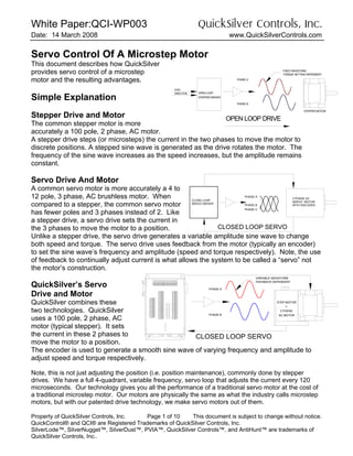
  • 1. White Paper:QCI-WP003 QuickSilver Controls, Inc. Date: 14 March 2008 www.QuickSilverControls.com Property of QuickSilver Controls, Inc. Page 1 of 10 This document is subject to change without notice. QuickControl® and QCI® are Registered Trademarks of QuickSilver Controls, Inc. SilverLode™, SilverNugget™, SilverDust™, PVIA™, QuickSilver Controls™, and AntiHunt™ are trademarks of QuickSilver Controls, Inc.. Servo Control Of A Microstep Motor This document describes how QuickSilver provides servo control of a microstep motor and the resulting advantages. Simple Explanation Stepper Drive and Motor The common stepper motor is more accurately a 100 pole, 2 phase, AC motor. A stepper drive steps (or microsteps) the current in the two phases to move the motor to discrete positions. A stepped sine wave is generated as the drive rotates the motor. The frequency of the sine wave increases as the speed increases, but the amplitude remains constant. Servo Drive And Motor A common servo motor is more accurately a 4 to 12 pole, 3 phase, AC brushless motor. When compared to a stepper, the common servo motor has fewer poles and 3 phases instead of 2. Like a stepper drive, a servo drive sets the current in the 3 phases to move the motor to a position. Unlike a stepper drive, the servo drive generates a variable amplitude sine wave to change both speed and torque. The servo drive uses feedback from the motor (typically an encoder) to set the sine wave’s frequency and amplitude (speed and torque respectively). Note, the use of feedback to continually adjust current is what allows the system to be called a “servo” not the motor’s construction. QuickSilver’s Servo Drive and Motor QuickSilver combines these two technologies. QuickSilver uses a 100 pole, 2 phase, AC motor (typical stepper). It sets the current in these 2 phases to move the motor to a position. The encoder is used to generate a smooth sine wave of varying frequency and amplitude to adjust speed and torque respectively. Note, this is not just adjusting the position (i.e. position maintenance), commonly done by stepper drives. We have a full 4-quadrant, variable frequency, servo loop that adjusts the current every 120 microseconds. Our technology gives you all the performance of a traditional servo motor at the cost of a traditional microstep motor. Our motors are physically the same as what the industry calls microstep motors, but with our patented drive technology, we make servo motors out of them. PHASE B PHASE A OPEN LOOP STEPPER DRIVER OPEN LOOP DRIVE DIRECTION STEP STEPPER MOTOR FIXED WAVEFORM TORQUE SETTING DEPENDENT CLOSED LOOP SERVO STEP MOTOR 2 PHASE = PHASE A PHASE B AC MOTOR FEEDBACK DEPENDENT VARIABLE WAVEFORM PHASE B PHASE A PHASE C 3 PHASE AC SERVO MOTOR WITH ENCODER CLOSE LOOP SERVO DRIVER CLOSED LOOP SERVO
  • 2. White Paper:QCI-WP003 QuickSilver Controls, Inc. QuickSilver Controls, Inc. Page 2 of 10 Detailed Explanation Stepper Drive and Motor PHASE B PHASE A OPEN LOOP STEPPER DRIVER OPEN LOOP DRIVE DIRECTION STEP STEPPER MOTOR FIXED WAVEFORM TORQUE SETTING DEPENDENT The common stepper motor is more accurately a 100 pole, 2 phase, AC motor. A stepper drive steps (or microsteps) the current in the two phases to move the motor to discrete positions. A rough sine wave is generated as the drive rotates the motor. The frequency of the sine wave increases as the commanded speed increases, but the amplitude remains constant. The permanent magnet in the rotor is attracted to the magnetic field generated by the windings. To produce torque, the motor requires a following error, as no torque is produced when the rotor magnet is fully aligned with the stator field. A variation in load torque requirements causes a variation in the following angle, with braking causing an overshoot if the motor must supply negative torque (braking). Exceeding the torque capabilities of the motor may cause the motor to lose steps, change speed, or even change direction! The normal prevention for these errors involves limiting the use of torque to approximately 1/3 to ½ of the motor capability as well as careful tailoring of the motion profile. This may be especially difficult in the presence of varying load and variable system backlash. The torque produced by this system varies with the following angle between the stator field and the rotor magnet. Each step change in position of the winding fields results in an impulse in the driving torque. The amplitude of these impulses is by microstepping, but the impulse nature remains, imparting acoustical noise to the system. The torque variation with position error may be approximated a rotary spring; this spring interacts with the rotary inertia of the system producing strong resonances which may produce ringing and long settling times as well as frequencies of operation with little effective torque. See the FAQ.
  • 3. White Paper:QCI-WP003 QuickSilver Controls, Inc. QuickSilver Controls, Inc. Page 3 of 10 Servo Drive And Motor PHASE B PHASE A PHASE C AC MOTOR 3 PHASE SERVOMOTOR 3-PHASE 3-PHASE CLOSED LOOP A common servo motor is more accurately a 4 to 12 pole, 3 phase, AC or DC brushless motor. When compared to a stepper, the common servo motor has fewer poles and 3 phases instead of 2. Like a stepper drive, a servo drive sets the current in the 3 phases to move the motor to a position. There are three types of drives in common use: AC brushless use sinusoidal commutation while DC brushless commonly use either a 6 step or 12 step commutation. The commutation circuits/subroutines of the drive vary the current to the windings as the rotor moves, keeping the angle between the stator field and the rotor near the optimal point to produce torque. In the case of the sinusoidal AC brushless controllers, this angle may be closely regulated, minimizing the torque ripple in the system. The 6 step and 12 step DC brushless designs, with their larger commutation steps, more closely approximate the discrete steps in commutation of the DC brush motor with limited commutator segments. The larger steps result in larger variation in the angle between the stator field and the rotor magnet, resulting in greater torque ripple. The most significant differences between the open loop stepper and the servo drive are how the speed of the drive is determined and how the torque is regulated. The stepper drive varies the position and speed of the stator field without regard for the rotor position, whereas the servo motor varies position and speed of the stator field as a direct result of position in the process of commutation. The torque of the stepper is passively modulated by the variation of the following error between the stator magnetic field and the rotor, where as the servo requires a feedback sensor to measure the error between commanded position and actual position, with the control equation actively varying the strength of the stator field to vary the torque. In the case of the servo, a sudden change in load requirements may introduce position error, but not the loss of synchronism between drive and the motor as the drive is made aware of the motor dynamics by the feedback sensor. Note: The use of feedback to actively adjust torque by adjusting the winding currents is what allows the system to be called a “servo”. It is not the construction of the motor.
  • 4. White Paper:QCI-WP003 QuickSilver Controls, Inc. QuickSilver Controls, Inc. Page 4 of 10 Unlike a stepper drive, the servo drive generates variable amplitude drive waveform to change both speed and torque. QuickSilver’s Servo Drive and Motor CLOSED LOOP SERVO STEP MOTOR 2 PHASE = PHASE A PHASE B AC MOTOR FEEDBACK DEPENDENT VARIABLE WAVEFORM QuickSilver combines these two technologies. QuickSilver uses a 100 pole, 2 phase, AC motor (typical stepper). When operating in closed loop mode, the currents to the two phases are modulated in a sinusoidal manner with the phase and frequency controlled by the feedback encoder, and the amplitude controlled by a control law based on the target and actual trajectories. This mode of operation is in the same manner as was for the three phase AC brushless servos, with full 4-quadrant (drive and regenerative breaking) capabilities. This is not just the common “position maintenance” mode with an open loop stepper and an encoder to adjusting the position of a stepper at the end of travel to after it has lost steps. QuickSilver takes advantage of the high torque capability available with high pole count motors designed for use as steppers as well as their low cost made available by the economies of scale for this motor type. We also take advantage of the ability of these motors to passively hold position when stopped by automatically switching between closed loop operation and a monitored open loop operation when stationary. This Anti-Hunt™ capability prevents the dithering or hunting commonly present in servo systems when stationary. If the error is caused to exceed the set position error threshold, the system reverts to closed loop until it again reduces the position error to below the configured limits.
  • 5. White Paper:QCI-WP003 QuickSilver Controls, Inc. QuickSilver Controls, Inc. Page 5 of 10 Advantages Advantages over Servo: • 2 to 4 Times the Holding Torque in the same size package. • Superior Torque Up to 1000-2000 RPM. • 100:1 Inertial Miss-match o Eliminates Gearheads • Cost • Single Cable For Motor and Encoder • Anti-Hunt™: No Servo Dither Advantages over Stepper • Higher Speed • No low-speed and mid-speed Resonances (see FAQ below) • 4 Times More Efficient (Typical) o Less Heating o Lower Energy Costs o See FAQ Below • More Usable Torque Our motors yield 2 to 4 times the continuous torque of comparably sized traditional servo motors due to their high pole count. This effect is termed “magnetic gearing” due to the torque multiplication associated with increased pole counts. The high resulting torque often allows these motors to directly drive a load without the need of an intervening gearbox leading to the industry term “High-Torque Direct Drive” motors. Quicksilver combines the high torque capabilities of the motor with patented motion control and digital drive techniques, providing direct drive capability for high inertial loads. These load inertias may be as large as 100 times the motor inertia (100:1 inertia mismatch) while still providing smooth responsive positioning control. Traditional systems typically cannot exceed a 10:1 inertial mismatch. This often eliminates gearheads for inertial mismatch reduction. QuickSilver’s Technology Software within the DSP models the motor as well as the driver, eliminating costly offset-and- noise-prone current sense circuitry. The model controls the on-chip PWM peripherals, directly controlling the timing of the full bridge drivers to the motor windings. The result is a true all- digital control system. This drive technology incorporates a patented “gated anti-phase” methodology which provides full 4 quadrant control of the motor windings with excellent linearity through zero. The use of modeling allows predictive control of the motor drivers, minimizing the effects of time lag in the control loop, allowing very low inductance motors to be used. The low time constant of the resulting system produces highly dynamic results: 1.8 degree “step motors” operating to approximately 4000 RPM.
  • 6. White Paper:QCI-WP003 QuickSilver Controls, Inc. QuickSilver Controls, Inc. Page 6 of 10 The motor – which most controllers employ as an open loop step motor – is operated as a high pole-count PM synchronous AC motor. The phase current is sinusoidally commutated as the motor rotates, with the control loop varying the magnitude of the current and thus the torque to achieve the desired position. Closed loop control of the motor eliminates low speed resonances by eliminating their source (see FAQ below), while simultaneously minimizing the heat produced and maximizing the available torque to the application. The result is faster and more precise motions for the end user, with enough energy cost savings to provide a rapid ROI over the apparently less expensive open-loop stepper system. Motor History The early history of electric power generation split early into two camps, Alternating current (AC) and Direct current (DC) by Westinghouse and Edison, respectively. The DC motors could be operated easily at variable speeds, but required a brush commutator to keep the motor spinning, while the AC motors (synchronous and induction) tended to operate over a much narrower speed range, tied to the power line frequency, unless special techniques were used. The commutator typically consisted of metal segments connected to (typically) the rotor windings, with the DC power applied through sliding contacts made of carbon, metal, or a mix of the two. These brushes generated electrical noise, dust, and they required regular maintenance. These were improved upon by moving the coils to the stator, and providing chopped waveforms to the coils by means of electronic switches. A precision DC brush motor has many commutating segments, and thus is able to compensate for the rotation of the rotor by adjusting the angle of the magnetic field of the rotor with respect to the stator in many small steps. This helps keep the torque produced steady and reduces cogging. Each segment produces a step in an approximately sinusoidal commutation waveform (by changing the paths of the current through the windings in the rotor. Most Brushless DC motors, on the other hand, use 3 hard switched phases controlled by position sensors to produce this function. These motors often have specialized windings and magnetic structures to produce “Trapezoidal” waveforms to minimize the toque ripple as these motors rotate. Special care is needed to precisely locate the commutating point for these units as even a small phase error may produce a significant pulsating torquei . DC Brushless motors with approximately sinusoidal Back EMF waveforms driven with trapezoidal waveforms also produce significant toque ripple in their operation. The variable speed control of the AC motors came from a different starting point. Commonly three phase motors were used with variable speed drives which produced a variable speed variable amplitude 3 phase sine waves to operate these motors at the desired speed. This process has been applied to both synchronous and induction AC motors. These motors are typically wound for sinusoidal back EMF. The AC servo motor, also called a Brushless AC servo motor grows out of this second branch, using sinusoidal drive signals with sinusoidal back EMF motors. The speed and amplitude of the sine waves is based on the desired torque as well as the motor type. For AC synchronous motors, the frequency and phase are locked to the speed and position of the rotor with respect to the stator. The control of the AC induction motors also involves controlling the rate of slip between the rotor and the stator to control the rotor currents and thus the torque produced by the interaction of the rotor magnetic field with the stator field. The advantage of the AC servos is that by making use of continuously varying sine waves rather than discontinuous trapezoidal
  • 7. White Paper:QCI-WP003 QuickSilver Controls, Inc. QuickSilver Controls, Inc. Page 7 of 10 waveforms, smoother operation may be obtained, even in the face of slight phasing errors. The disadvantage is that the accurate generation of multiple sine waveforms is not a simple task. Where as the DC brushless driver could use a relatively simple switched inverter with DC current sensing in the ground leg to set the wanted average DC current through the motor, the AC drive must generate a sine wave through each winding, requiring multiple control loops and multiple current sensors (or estimators). The bipolar stepper motor is a high pole count synchronous AC motor. The speed of a synchronous motor is proportional to the line frequency and inversely proportional to the number of poles. That is, a synchronous motor moves forward one pole pair for each 360 electrical degrees of the applied sine wave. A stepper motor, having commonly 100 poles (50 pairs), produces a reduced speed of operation. This effect is often referred to as magnetic gearing. This high pole count has the same effect as physical gears in that the speed is reduced and the torque is increased from the motor in proportion to the number of poles. High pole count AC synchronous motors were first produced to run from line frequency to provide a low speed/high torque motion without gears. Other engineers noticed that these same motors could be operated at variable speeds down to zero by switching the current through the phases, which was very useful for controlling machine tools. The stepper motor was “born.” These motors, due to their high pole count, have very high torque constants. Their use in open loop positioning, however, also requires a steep torque vs. position characteristic so as to have the motor come to rest over a narrow angle range even in the presence of friction and load. The high pole count helps here as well. With their typical sinusoidal torque constant repeating every two poles, the higher the pole count, the smaller the mechanical angle corresponding to a full electrical cycle. Thus for a given motor size, not only does the torque scale up roughly proportional to the pole count, but so does the number of electrical cycles. This means that quadrupling the number of poles makes for some four time the torque with the electrical cycle increment in one quarter of the mechanical angle. The maximum slope of such a sine wave shaped torque curve is sixteen times as steep. In comparing a 6 pole motor to a 100 pole (1.8 degree) stepper, these combined effects results in a torque slope factor which is some 278 times as steep. This characteristic high stiffness has allowed the use of stepper motors in high accuracy open loop operation. Their extensive incorporation into open loop designs has led to their production in large quantities leading to optimized tooling with the benefits of quantity of scale: High Quality and Low Price. The desire to make these motors perform smoother motions has led to motors optimized for “micro-stepping” - that is having a good sinusoidal torque constant and low detent torque characteristics. It is these same motor characteristics that improved the open loop “stepper-motor” operation, namely high torque constant, high torque to inertia ratio, sinusoidal per-phase torque constants, and low cogging torque, that are equally useful to closed loop servo control of these high pole count, poly-phase AC synchronous motors. The use of Permanent Magnet AC Servo Motors is increasing due to the higher efficiency compared to induction motors with a more comparable price than past years due to the increased cost of copper and the reduced cost of magnets.
  • 8. White Paper:QCI-WP003 QuickSilver Controls, Inc. QuickSilver Controls, Inc. Page 8 of 10 Frequently Asked Questions What Makes It A “Servo”? The Merriam-Webster Dictionaryii defines a servomechanism as “an automatic device for controlling large amounts of power by means of very small amounts of power and automatically correcting the performance of a mechanism.” One of the earlier known servoiii (from Latin Servus slave) systems dates back to approximately 270BC and was a regulator for the water level used by the water clocks of the day to help them keep more accurate time by keeping the water level constant, and thereby the water pressure exiting the tank constant. The water passed through a fixed size orifice and filled a fixed volume before it dumped and refilled. Each dumping of the volume represented one “tick” of the clock. The water level regulator worked similarly to the float mechanism used in current day toilet tanks. In this case, the feedback is in the form of the level of the float, and the difference in level from the desired level operates a valve so as to keep the water level within the desired range. Servo motion control systems use position and/or velocity sensors to measure the difference between the desired and actual operation of the actuator. Amplifiers (electronic, mechanical, hydraulic, magnetic, etc.) are used to increase the power of the error signal and to affect the operation of the actuator so as to make the actuator perform the desired motion. The SilverLode™ system uses optical incremental encoders to measure the motor rotary position, digital signal processors to process it, and drive electronics to provide the power drive to the motor to effect the motion. But Do Not Stepper Motors Have Resonance Problems? Stepper motor resonance arises in open loop operation due to the steep torque vs. position error characteristics of an open loop stepper operating in the vicinity of the zero error angle. When disturbed from this zero error angle (or that angle is suddenly changed, such as by changing the currents through the windings as happens when the motor is “stepped”), the rotor of the motor operates as a rotary pendulum, the resulting torque of the motor causing the rotor to accelerate towards and then pass by the equilibrium point, only to then slow and reverse again with a slightly lower amplitude due to losses, repeating until the rotor finally comes to rest at the (new) equilibrium point. If the motor is pulsed near the resonance frequency, the pendulum effect will cause the amplitude of this oscillation to continue to grow until the rotor is more than 2 full steps away from the original equilibrium point. At this point the nearest new equilibrium point is now 4 steps (one full electrical cycle) away from the old equilibrium point, and the generated torque will cause the rotor to accelerate toward that point. The motor has lost synchronization with the applied waveform and thus “lost” steps. According to the speed of operation, the motor may stall, may operate erratically, or may even change speed and direction! What Causes The Low Speed Resonance In A Stepmotor? The low speed resonance of the open loop step motor is a result of the motor operating as a spring-mass system about its equilibrium point. The motor torque is approximately a sinusoidal
  • 9. White Paper:QCI-WP003 QuickSilver Controls, Inc. QuickSilver Controls, Inc. Page 9 of 10 function of its position error. This “spring” interacts with the rotary inertia of the motor to form, in essence, a rotary pendulum. As the motor is stepped (or microstepped) the equilibrium point is moved, causing the “pendulum” to seek the new equilibrium point. If the stepping rate approaches the natural frequency of this “pendulum”, the amplitude of the swinging increases, often causing the motor to lose synchronization with its drive signals. When this same motor is operated as an AC servo motor, the commutation keeps the magnetic field positioned so as to produce the maximum torque for the commanded current magnitude. A perturbation of the rotor angle results in the magnetic field shifting rather than the torque changing. Without the position dependent torque term, the spring effect is eliminated as well as the associated low speed resonance problem. But Don’t Stepper Motors Run Hot? A side benefit of operating the motor at the optimal torque angle is that only the current needed to produce the torque actually needed is applied to the motor. There is not a need to supply full current unless the peak torque is being utilized. Given that the “rule of thumb” for operation of a stepper motor is to only use approximately 30% to 50% of the available torque, that same motor operated as a servo in the same application requires only 30% to 50% current. The main heating in the windings is P=I2 R, thus at 50% current, the heating is only 25% as compared to the open loop stepper, while at 30% utilization the heating is only 9%! The result is that the same “stepper motor”, when used as a servo may be operated quieter, smoother, and cooler, and with higher available torque while running over a wider range of speeds. And these improvements are available while at the same time avoiding the low speed resonance effects of the open loop stepper. But How Can The Motor Draw 2 Amps When The 48v Power Supply Is Only Supplying 160 Ma? The driver and controller form what is effectively as step-down switching power supply. The power into the Controller, minus the relatively low losses of the driver and the power to the DSP and other electronics, produces the mechanical output power from the motor plus motor heating. When the motor is stopped, there is no mechanical output power (P=speed * Torque), and thus the power into the motor is all heating. In the case of a motor with a 1.2 ohm winding, this is on the order 4.8W, and would account for approximately 100mA at 48v. Additional input power is required for the electronics including the losses in the drivers; in the given example this would account for the other 60mA of supply current. The low current usage only lasts while the motor is not providing mechanical work. As the motor spins faster and/or the torque increases, the mechanical output power increases. This additional power must be supplied from the power supply, and the input current goes up. What Is Anti-Hunt™? Just because the motor can be operated as a high performance servo system does not mean that it can not be switched back to its humble open loop beginning. When the motor is sufficiently close to the desired position, the operating mode of the motor can be switched to open loop operation at a user defined current level. With the servo loop turned off, the hunting or dithering of the servo loop is eliminated. If the motor position is disturbed or another motion is requested, the servo operation is then restored. This allows for rapid motions with quick settling as afforded by the servo control while still retaining the ability to stop solidly without
  • 10. White Paper:QCI-WP003 QuickSilver Controls, Inc. QuickSilver Controls, Inc. Page 10 of 10 dithering. This eliminates acoustical noise and movement that would affect applications such as imaging. The ability to eliminate dithering when stopped also reduces wear on any attached lead screws or gears that the continual hunting of a servo may cause even when there is no motion commanded, often extending the life of the attached mechanism. i http://www.ornl.gov/~webworks/cpr/pres/107923_.pdf ii www.merriam.com iii originally http://www.control-systems.net/recursos/articulos/002.htm, no longer posted, but may be available on www.archive.org