IRJET- Design of Two-Stage Single Speed Gearbox for Transmission System of SA...
98375_DIRT CRUSADERS
1. 1
TEAM DIRT-CRUSADERS
Team ID 98375
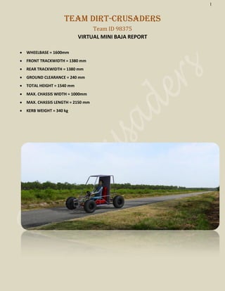
VIRTUAL MINI BAJA REPORT
WHEELBASE = 1600mm
FRONT TRACKWIDTH = 1380 mm
REAR TRACKWIDTH = 1380 mm
GROUND CLEARANCE = 240 mm
TOTAL HEIGHT = 1540 mm
MAX. CHASSIS WIDTH = 1000mm
MAX. CHASSIS LENGTH = 2150 mm
KERB WEIGHT = 340 kg
2. 2
CHASSIS
The main objective of developing the chassis is to
make a firm wireframe that can accommodate all
components of the vehicle efficiently and provide
maximum safety to the drivers.
CAD MODEL OF THE CHASSIS:
The First designed chassis model is given below:
Shortcomings:
A arm mounting problem
Rear end too big
No provision to mount suspension
Complicated to fabricate
This is the evolved model in response to the above
shortcomings
MATERIAL SPECIFICATION:
Plain carbon steel SAE 1020/ ASTM A513
alloys 1020
Yield strength 450 MPa
Ultimate strength 600-620 MPa
Rockwell hardness B89
Composition(%)
Fe C Mn P S
99.08 0.18~0.23 0.3~0.6 0.04max 0.05max
Calculation of CG and Mass Distribution
Unsprug weight = 260 Kg
CGX =1287.3 CGY = -8.85
CGZ = 612.3
TABS
Tabs to mount (5KN)
(Syt = 350 MPa)
Tabs provide FOS = 3
Pin Provides FOS = 2.5
Pin is made weaker.
Tab Thickness = 8 mm
Analysis Using ANSYS
I. Pre-processing
C/S of Main pipe:
OD 26.67mm
T= 3.917 mm
C/S of auxiliary pipe:
OD 26.67mm
T= 2.84 mm
Common properties
Density 7860 kg/m3
Poisson’s ratio 0.3
Young’s modulus
205GPa
(Dim are in mm)
Meshed View
ITEM WEIGHT X Y Z
Chassis 60 1120 0 700
Engine 50 1700 900 490
Gear Box 20 1700 110 350
Seat 10 1300 0 640
Driver 110 1200 0 690
Front
Assemblies
10 350 0 340
3. 3
Analysis of Four cases
1. Static Bending – all Forces Distributed
according to Weight distribution(g acc)
2. Toppled condition- All Forces applied in the
Upward direction according to Wt Dist.(2.5g)
Crash analysis:
3. Front Impact
a. Vehicle to Rigid body impact
b. Assuming Crash pulse = 0.185 sec
c. Equivalent Acceleration = 90 m/s2
d. Force multiplier = 9.174g
4. Side Impact
a. Vehicle to vehicle impact
b. Force Multiplier = 5 g
Improvements tested
1. RRH cross member(LDB)
2. SIM Cross members
3. Floor Bracing
a. At 45o
From Max Strain point – Showed
very poor results
b. Two parallel Floor bracing members-
Subjected to Buckling
c. Two members from max strain point to SIM
cross member Common point
And one member joining them-
Showed very good results in both
front and side impact
Prevent Buckling of SIM and LFS
Topp
le
Stat
ic
Front
impact
Side impact
Simple X(518MPa) X(350Mpa)
With
bends
X(518MPa) X(518MPa)
With Cross
Member
Improved
(417 MPa)
Improved
(200MPa)
Floor
bracing
Max stress
point
relocated
(Increased
safety)
(130MPa)
Expected Improvements using Crash Tube
• Assuming 10 cm
of Crash length
of crash tube.
• The given length
can absorb as
much as 70% of
damage
provided that its perfect frontal collision.
Human ergonomics
Provides Given Head clearance and side clearance
Easy exit
5. 5
TRANSMISSION SYSTEM
Engine Power :- 10 Hp at 3000 rpm
Engine torque :- 19.68 Nm
Ideal engine rpm :-1750 rpm
Maximum speed :- 3800 rpm
Torque is considered constant :-19.65 Nm
Overall efficiency :-80%
Rear Wheel size :- 23 Inch
Since it is a full floating axle therefore we need to design only on basis of torsion.
Selecting material for axle as C45 and FOS as 3.
Diameter comes out to be 22mm.
Approximate Torque required for gradient of 25 is 6.329 Nm.
As the gear is mounted on the left side of the engine(as seen from rear) due to space constrains ,
using helical gear pair for direction changing as coupling member for engine and gear box
6. 6
Helical gear specification
Precision Grade JIS Grade N6 ,JIS Grade 2
Gear teeth Standard full depth
Pressure angle 20 deg
Helix angle 17deg
Material SCM440 (Alloy Steel)
Gear No 1 2 3 4 Reverse
Gear ratio 31.48 18.70 11.40 7.35 55.08
Traction
(N)
1694.165 1006.38 631.52 395.56 2964.25
Range of vehicle speed
(kmph)
10-14 18-22 30-36 46-57 6-8
Torque at Differential
(Nm)
619.52 367.45 224.01 144.43 1082.32
Actual torque available at both the
wheel(Nm)
495.62 293.96 179.208 115.54 865.8
Bell crank angle(for gear shifting) 56.25 42.83 30.12 -11.55 51.5
SUSPENSION SPECIFICATIONS
Double Wishbone Unequal Arms
Front suspension
Spring Stiffness Front = 25 N/mm (Passion)
Free Length with Damper Front = 34.29mm
Max. Compression allowed = 110mm
Rear Suspension
Spring Stiffness Rear = 44N/mm (Yamaha Rx-100)
Free Length with Damper Front = 35mm
Max. Compression allowed = 120mm
Wheelbase = 1600 mm
Front and Rear Trackwidth = 1380 mm
Front Kingpin angle = 10.61 deg
Front Camber angle = -2 deg
Toe in = -1 deg
Front Castor Angle = 3 deg
Scrub Radius = 22.11mm
7. 7
Sprung Mass = 260 kg
C.G. Along X-axis = 1287.3 mm
Designed for Bump of 100mm And Droop of 100 mm
Calculated Results
Motion Ratio = 0.3(Front)
= 0.337 (Rear)
Front Ride Frequency = 1.078 Hz
Rear Ride Frequency = 1.258 Hz
Bounce Frequency = 1.19 Hz centre at 5099.33 mm Front
Pitch Frequency = 1.15 Hz centre at 148 mm Rear
Graphs
CHANGE IN CAMBER ANGLE CHANGE IN ROLL CAMBER
CHANGE IN TOE ANGLE UPRIGHT ANLYSIS
8. 8
STEERING SYSTEM
NAME COST WEIGHT SENSITIVITY
AND RESPONSE
EFFICIENCY
Rack and pinion Low Light Good Good
Recirculating ball
type
High Medium Poor Very good
Worm and roller Medium Heavy Poor Medium
Worm and
sector
Medium Heavy Very poor Good
Hence we selected rack and pinion steering system from above given table
Steering ratio of the system as 17:1
Turning radius R= 2.886m
ACKERMAN ANGLE (for 540 degree of rotation of steering wheel)
Inner wheel turning angle = 41.746 degree
Outer wheel turning angle = 25.636 degree
OVERSTEERING CONDITION
Same tyres are used for both Front and Rear
C.G is more towards rear axle
k= - 0.034 deg.sec2/m
9. 9
TIE ROD LENGTH
The length of the tie rod is found to be 385 mm.
3-D MODEL IN CATIA
10. 10
BRAKES
Assumptions and Given Data:
Mass of vehicle = 350 kg
o Vertical height of C.G above ground = 0.6m
o Co-eff. Of friction between tyre and road = 0.7
o Track width = 1.38m
o Wheel base = 1.6m
o Wheel dia = 23” and rim dia = 11”
o Test speed = 52kmph = 14.44m/s
o Static load distribution: Front axle = 40%, Rear axle = 60%
o Co-eff. Of friction of brake lining = 0.4
o Pedal Ratio = 8
o Tandem master cylinder bore dia = 19mm
o Caliper piston dia = 48mm
o Disc diameter 7 inches with effective radius of 6cm
Calculated Data:
o Stopping Distance = 15.18m
o Deceleration = 6.87m/s2
(0.7g)
o Dynamic Load Distribution: Front Axle = 118.085kg, Rear Axle = 231.915kg
o Braking Force = 2404.5 N
o Braking Torque = 702.35 N-m
o Clamp Load on all 4 wheels = 14632.29 N, on single wheel = 3658.07 N
o Calliper piston pressure=2.02 MPa
o Force on Tandem Master Cylinder Piston = 573.16 N
o Pedal Force = 71.645 N
o Energy Losses:
o K.E=36490 J
o P.E=2427.85 J fr 450
slope
o Total Energy=38917.85 J, Average Power=18.53 kW
Time on Brake=2.1 seconds
11. 11
DESIGN VALIDATION PLAN
1. Ansys analysis of Chassis
a. Static
b. Impact
2. Static testing of suspension
3. Sample Testing of welded joints on chassis
4. Sample Testing of bends on chassis
PROJECT PLAN
Work Profile Date
PVC Pipe Model 21-26 Aug
Trials of Different Weld joints as per Roll cage
Design and its Destructive Testing
27 Aug – 2 Sept
Chassis Manufacturing (Cutting tubes to
parameters)
6 – 12 Sept
Chassis manufacturing (Welding) 13 – 25 Sept
Assembling A-Arms with Chassis and upright 25 Sept – 2 October
Brakes and Wheel Hub Assembly 3-10 Oct
Positioning of Master Cylinder, Seat 11-17 Oct
Positioning of Steering Rack,
Pedal and Gear Changer
18-24 Oct
Finalizing the Chassis(without Engine and Gear Box
mounting)
1st
Nov
Engine Order placement According to BAJA specified Dates
Engine Mounting and Gear Box Mounting After Receiving Engine (around Jan 2013)
Vehicle Ready for Road test in Campus Around 10-15 Jan 2013
12. 12
Components Order Placement
Chassis(Tubes, Metal Plates for tabs) 3-6 Sept
Joints(Hiem, Ball) 7-23 Sept
Bolts and Nuts 7-23 Sept
Front And Rear Upright 7-23 Sept
Brake Parts 20 Sept – 5 Oct
Seat and Seat Belt 30 Sept – 7 Oct
Steering Assembly 30Sept – 14 Oct
Electricals 7 Oct – 20 Oct
Gear Box and Axles 30 Sept – 10Nov
Tyres and Rims 10 Sept – 30 Sept
13. 13
College Facilities Outside Facilities
All types of welding -Milling
Cutting -Gear Cutting
Drilling -Destructive test of Welds
Bending -Jig Boring
Tapping and Threading
COST REPORT
SYSTEM COST (Rs.)
Chassis 20000/-
Transmission 20000/-
Suspension 28000/-
Rims & Tires 35000/-
Steering 5000/-
Braking 38000/-
Engine 17000/-
Electrical System 20000/-
Seat 10000/-
Paint 5000/-
Total: 198000/-
DFMEA ( Transmission System) :
Item Function Failure Mode Severity Cause Occurre
nce
Detectio
n Rating
Risk
Priority
Number
Remedies
1.
Transaxl
e
Gearbox
Power
transmis
sion,
Gear
reductio
n,
Different
ial.
a.
misalignment
8 Shocks
and
vibratio
ns
2 1 16 Use of rubber mountings,
Proper alignment, Reduction of
shocks and vibrations through
use of suspension system.
b.
wear of
multiplate
clutch
8 Lubricat
ing fluid
leakage
/ low
viscosit
y index
1 2 16 Check for leakages, Replace
lubricating fluid if necessary.
c. 6 Lubricat 1 2 12 Check for leakages, Replace
14. 14
overheating ing fluid
leakage
,
Improp
er air
cooling
lubricating fluid if necessary.
Correct placement to facilitate
airflow over the unit surface.
2.
Full
Floating
Axle
Torque
transmis
sion.
a.
Torsion
Failure
8 Overloa
ding
1 1 8 Axle size is calculated using the
failure criteria and safe values
are obtained.
b.
misalignment
8 Shocks
and
vibratio
ns
2 1 32 Proper alignment, Reduction of
shocks and vibrations through
use of suspension system.
c.
Wear of
rubber
coupling
8
Harden
ed
rubber
due to
chemic
al
contami
nation
1 3 24 Replace with spare.
DFMEA (Crash Tube (chassis component)):
Item Function Failure Mode Severity Cause Occurre
nce
Detectio
n Rating
Risk
Priority
Number
Remedies
Crash
Tube
Destruct
ive
absorpti
on of
impact
energy
a.
damage to
chassis
without
crash tube
9 Frontal
Impact
4 1 36 Use of crash tube absorbs most
of impact damage thus
protecting the chassis
b.
damage to
chassis with
crash tube
9 Frontal
Impact,
Short
crash
tube
4 1 36 Size of crash tube is optimized
so that there is minimum or no
damage to chassis.