Digital Servo Drive SynqNet Interface
•
0 likes•113 views

The DQ111SE-H Series digital servo drives are designed to drive brushed and brushless servomotors. They employ Space Vector Modulation and vector control technology to achieve high bus voltage utilization and reduced heat dissipation. The drives feature dedicated digital and analog inputs and outputs as well as a SynqNet interface for networked motion control applications.

Recommended
Recommended
More Related Content
What's hot
What's hot (20)
Viewers also liked
Viewers also liked (14)
Similar to Digital Servo Drive SynqNet Interface
Similar to Digital Servo Drive SynqNet Interface (8)
More from Electromate
More from Electromate (20)
Recently uploaded
Recently uploaded (20)
Digital Servo Drive SynqNet Interface
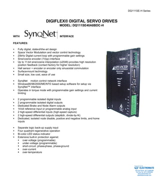
- 1. DQ111SE-H Series DIGIFLEX® DIGITAL SERVO DRIVES MODEL: DQ111SE40A8BDC-H WITH INTERFACE FEATURES: · Fully digital, state-of-the-art design · Space Vector Modulation and vector control technology · 20kHz Digital current loop with programmable gain settings · Sine/cosine encoder (1Vpp) interface · Up to 11-bit sine/cosine interpolation (x2048) provides high resolution position feedback (contact factory for higher resolution) · Hall sensor + encoder or encoder only sinusoidal commutation · Surface-mount technology · Small size, low cost, ease of use · SynqNetä motion control network interface · Windows95/98/2000/ME/NT© based setup software for setup via SynqNet™ interface · Operates in torque mode with programmable gain settings and current limiting · 2 programmable isolated digital inputs · 2 programmable isolated digital outputs · Dedicated Brake and Node Alarm outputs · 14-bit reference input or programmable analog input · 2 high-speed differential inputs (high-speed capture) · 2 high-speed differential outputs (step&dir, divide-by-N) · Dedicated, isolated node disable, positive and negative limits, and home inputs · Separate logic back-up supply input · Four quadrant regenerative operation · Bi-color LED status indicator · Extensive built-in protection against: § over-voltage (programmable) § under-voltage (programmable) § short-circuit: phase-phase, phase-ground § over-current § over-temperature Sold & Serviced By: ELECTROMATE Toll Free Phone (877) SERVO98 Toll Free Fax (877) SERV099 www.electromate.com sales@electromate.com
- 2. ADVANCED MOTION CONTROLS DQ111SE-H Series LOGIC POWER GROUND OUTPUT PULL-UP MOTOR A REF MARK + REF MARK - Sold & Serviced By: Page 2 of 7 BLOCK DIAGRAM: SynqNet INTERFACE 20K 5K 5K 20K MOTOR FEEDBACK PROCESSOR DQ111SE...BDC-H ISOLATION I/O INTERFACE USER INPUT 0...1 USER GROUND + - 20K 20K +DIFF. OUT 0...1 -DIFF. OUT 0...1 +DIFF. IN 0...1 -DIFF. IN 0...1 +ANALOG INPUT -ANALOG INPUT 5K 500 USER OUTPUT 0..1, BRAKE, NODE ALARM USER GROUND MOTOR B MOTOR C LOGIC POWER SUPPLY HIGH VOLTAGE POWER OUTPUT STAGE COS + COS - SIN + SIN - SENSCOMMON +5V 20K 20K 2K +HALL A,B,C -HALL A,B,C +5V NODE DISABLE, LIMIT+, LIMIT-, HOME DESCRIPTION: The DQ111SE-H Series digital PWM servo drives are designed to drive brushed and brushless servomotors. These fully digital drives operate in torque mode and employ Space Vector Modulation (SVM), which results in higher bus voltage utilization and reduced heat dissipation. The command source can be generated internally or can be supplied externally. In addition to motor control, these drives feature dedicated and programmable digital and analog inputs and outputs to enhance interfacing with external controllers and devices. DQ111SE-H Series drives feature a SynqNetä interface for high-speed digital command operation in networked applications. Drive commissioning can be accomplished through a fully graphical Windows© based application via the SynqNet interface™. More information about SynqNetä can be obtained at http://www.synqnet.org. All drive and motor parameters are stored in non-volatile memory. ELECTROMATE Toll Free Phone (877) SERVO98 Toll Free Fax (877) SERV099 www.electromate.com sales@electromate.com
- 3. ADVANCED MOTION CONTROLS DQ111SE-H Series Sold & Serviced By: Page 3 of 7 SPECIFICATIONS: POWER STAGE SPECIFICATIONS DQ111SE40A8BDC-H DC SUPPLY VOLTAGE 20…80 VDC PEAK CURRENT 40A (28.3Arms) MAXIMUM CONTINUOUS CURRENT 20A (14.2Arms) MINIMUM LOAD INDUCTANCE 250 μH SWITCHING FREQUENCY 20 kHz HEATSINK (BASEPLATE) TEMPERATURE RANGE 0 to 65 ºC, disables at 65 ºC POWER DISSIPATION AT CONTINUOUS CURRENT 100W MIN. UNDER VOLTAGE SHUTDOWN 20 VDC MAX. OVER-VOLTAGE SHUTDOWN 86 VDC LOGIC SUPPLY VOLTAGE (backup supply) 20…80 VDC, 20W maximum MECHANICAL SPECIFICATIONS MOTOR CONNECTOR: P1 Removable screw terminal POWER CONNECTOR: P2 Removable screw terminal MOTOR FEEDBACK CONNECTOR: CN4* 15-pin high density female D-sub I/O CONNECTOR: CN3* 26-pin high density female D-sub SYNQNETä CONNECTOR: CN1, CN2* 8-pin RJ45 SIZE 7.50 x 4.40 x 1.41 inches 190.5 x 111.8 x 35.9 mm WEIGHT * Mating connectors are not included. ELECTROMATE Toll Free Phone (877) SERVO98 Toll Free Fax (877) SERV099 www.electromate.com sales@electromate.com
- 4. ADVANCED MOTION CONTROLS DQ111SE-H Series Commutation sensor inputs. Internal 2K pull-up to +5VDC. Can be used with single ended or differential Hall sensors. I Sold & Serviced By: Page 4 of 7 PIN FUNCTIONS: P1 - Motor Connector: CONNECTOR PIN NAME DESCRIPTION I/O 1 MA Motor phase A O P1 2 MB Motor phase B O 3 MC Motor phase C O P2 - Power Connector: CONNECTOR PIN NAME DESCRIPTION I/O 1 GND Ground GND 2 HV IN DC motor and power input. This input is used to supply power to the motor and drive logic circuitry. I P2 3 GND Ground GND 4 HV AUX Logic supply input. This input can be used to supply power to the drive logic circuitry only. Effective only when the voltage applied to pin P2-2 is lower then the voltage applied to P2-4. I CN4 - Motor Feedback Connector: CONNECTOR PIN NAME DESCRIPTION I/O 1 COS + Cosine input. Voltage range: 2 – 3.4 I 2 COS - VDC. Frequency range: DC – 200kHz I 3 SIN + Cosine input. Voltage range: 2 – 3.4 I 4 SIN - VDC. Frequency range: DC – 200kHz I 5 SGND Signal ground SGND 6 +Hall A I 7 -Hall A Commutation sensor inputs. Internal 2K pull-up to +5VDC. Can be used with single ended or differential Hall sensors. I 8 +Hall B I 9 -Hall B 10 +5V OUT +5V @ 250mA max. Short-circuit protected. O Commutation sensor inputs. Internal 2K pull-up to +5VDC. Can be used with single ended or differential Hall sensors. 11 +Hall C I 12 -Hall C I CN4 13 REF MARK + Reference mark from sine/cosine encoder I ELECTROMATE Toll Free Phone (877) SERVO98 Toll Free Fax (877) SERV099 www.electromate.com sales@electromate.com
- 5. ADVANCED MOTION CONTROLS DQ111SE-H Series Sold & Serviced By: Page 5 of 7 14 NC Not connected 15 REF MARK - Reference mark from sine/cosine encoder I CN3 – I/O Connector: CONNECTOR PIN NAME DESCRIPTION I/O 1 USER OUTPUT 0 Programmable digital output. Isolated, 24VDC, referenced to USER GND O 2 USER OUTPUT 1 Programmable digital output. Isolated, 24VDC, referenced to USER GND O 3 USER GND Ground reference for user outputs and inputs. GND 4 NODE ALARM SynqNet network error. Isolated, 24VDC, referenced to USER GND O 5 BRAKE Brake output, controlled directly via SynqNet. Isolated, 24VDC, referenced to USER GND O 6 AGND Analog ground AGND 7 + DIFF. INPUT 0 Differential input. 5V TTL., non-isolated. I 8 - DIFF. INPUT 0 Programmable function: capture I 9 OUTPUT PULL-UP 5K Pull-up for user outputs. I 10 NODE DISABLE Node disable input. Isolated, 24VDC range. Referenced to sensor common (SENSCOMMON). I 11 LIMIT + Positive limit input. Isolated, 24VDC range. Referenced to sensor common (SENSCOMMON). I 12 LIMIT - Negative limit input. Isolated, 24VDC range. Referenced to sensor common (SENSCOMMON). I 13 HOME Home switch input. Isolated, 24VDC range. Referenced to sensor common (SENSCOMMON). I 14 USER INPUT 0 Programmable digital input. Isolated, 24VDC, referenced to USER GND I 15 USER INPUT 1 Programmable digital input. Isolated, 24VDC, referenced to USER GND I 16 SENSCOMMON Sensor common. Used with E-stop, limit +, limit -, and home inputs. Can be used as a ground reference or as a pull-up for these inputs. COMMON 17 + DIFF. INPUT 1 Differential input. 5V TTL., non-isolated I 18 - DIFF. INPUT 1 Programmable function: capture I 19 SGND Digital ground SGND 20 + DIFF. OUTPUT 0 Differential output. 5V TTL., non-isolated. O Programmable function: 21 - DIFF. OUTPUT 0 step&dir, divide-by-N O CN3 22 + DIFF. OUTPUT 1 Differential output. 5V TTL., non-isolated. Programmable function: O ELECTROMATE Toll Free Phone (877) SERVO98 Toll Free Fax (877) SERV099 www.electromate.com sales@electromate.com
- 6. ADVANCED MOTION CONTROLS DQ111SE-H Series Sold & Serviced By: Page 6 of 7 23 - DIFF. OUTPUT 1 isolated. Programmable function: step&dir, divide-by-N O 24 +ANALOG IN Programmable, differential analog input, I 25 -ANALOG IN +/- 10V range, 14-bit. I 26 AGND Analog ground. AGND CN1 – SYNQNETä INTERFACE: CONNECTOR PIN NAME DESCRIPTION I/O 1 RD+ I 100BaseT receiver 2 RD- I 3 TD+ O 100BaseT transmitter 6 TD- O CN1 4, 5, 7, 8 N/C Not connected CN2 – SYNQNETä INTERFACE: CONNECTOR PIN NAME DESCRIPTION I/O 1 TD+ O 100BaseT transmitter 2 TD- O 3 RD+ I 100BaseT receiver 6 RD- I CN2 4, 5, 7, 8 N/C Not connected ORDERING INFORMATION: Standard model: DQ111SE40A8BDCX-H X indicates the current revision letter. ELECTROMATE Toll Free Phone (877) SERVO98 Toll Free Fax (877) SERV099 www.electromate.com sales@electromate.com
- 7. ADVANCED MOTION CONTROLS DQ111SE-H Series Sold & Serviced By: Page 7 of 7 MOUNTING DIMENSIONS: ELECTROMATE Toll Free Phone (877) SERVO98 Toll Free Fax (877) SERV099 www.electromate.com sales@electromate.com