Biothesiometer for Peripheral neuropathy
•
0 likes•1,202 views

Biothesiometer is a simple tool used for managing the peripheral neuropathy and diabetic neuropathy due to loss of vibration perception threshold (VPT). Biothesiometry Study helps to prevent diabetic foot ulcers. For more details visit www.digitalbiothesiometer.com.

Recommended
More Related Content
What's hot
What's hot (20)
Similar to Biothesiometer for Peripheral neuropathy
Similar to Biothesiometer for Peripheral neuropathy (20)
Recently uploaded
Recently uploaded (20)
Biothesiometer for Peripheral neuropathy
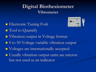
- 1. Digital Biothesiometer Vibrometer ◼ Electronic Tuning Fork ◼ Tool to Quantify ◼ Vibration output in Voltage format ◼ 0 to 50 Voltage variable vibration output ◼ Voltages are internationally accepted ◼ Usually vibration output units are micron but not used as an indicator
- 2. Feature contd.. ◼ Check key to confirm reading ◼ Computer connection thorough USB cable ◼ Windows based computer supports ◼ Data transfer to Computer ◼ Works in 200 ~ 230 Volts supply
- 4. Sample Report – Model 2 Developed for Denmark
- 5. Kit Content: ◼ Biothesiometer model VIBROMETER ◼ Vibration Probe ◼ Power Cord ◼ User Manual ◼ Padded Carry Bag ◼ Additional Fuse – 100mA Slow Blow(2 Nos.)
- 6. Interpretation of Result ◼ 15 Volts and less is considered Normal ◼ 16-20Volts – Mild, 21-25Volts – Moderate and >25Volts – Severe loss of vibration perception ◼ > 25Volts are considered high risk foot ◼ Scientific papers suggest 25volts and beyond are 7 times more vulnerable to get ulcer than a normal foot. ◼ They also warn that they are 23 times more vulnerable when the voltage is more than 42.
- 7. Vibrometer
- 8. Controls Mains socket on the back panel connects the power cord to the machine. A Fuse Holder is inbuilt. ON / OFF switch on the top switches on the electrical power to the machine. When on it glows in RED colour.
- 9. Digital display readout indicates the vibration output in Volts. 0 to 50 Volts are displayed. 5 Pin connector connects the vibration probe to the machine. Insert the probe and tighten the screw gently.
- 10. Patient is asked to respond when they feel the vibration. To reconfirm their response, CHECK key is used. When pressed, this will stop the vibration at the probe. Patient should respond correctly and if they fail, then the reading is not correct. For convenience CHECK is also present in the probe.
- 11. Volt rotary knob is used to increase or decrease the vibration strength. Clockwise rotation will increase the volt and vice versa. It is recommended to keep this knob at 0 volts before switching on the machine
- 12. The probe tip or the plunger is the point of contact with the patient. This tip should be placed on the object gently. Probe should not be pressed hard on the subject under test. Depending upon the strength of voltage selected this tip vibrates.
- 13. How to Change the Fuse ◼ Use a small screw driver ◼ Keep the driver on a slot appear in the mains socket. ◼ You may also see a fuse symbol on top of the carrier. ◼ Push the screw driver outside gently. ◼ The fuse holder will get pushed out.
- 14. ◼ Once the fuse holder is out, you may see 2 glass fuses. ◼ Fuse on the outside touched by the driver is the working fuse. ◼ Replace this fuse with the fuse kept on the outer side. ◼ Dispose the defective fuse
- 15. ◼ Push the fuse holder till it gets fixed with the mains socket. ◼ The value of the fuse used is 100mA Slow Blow, 20mm length and 5 mm Dia. ◼ Do not use fuse over or under rated than this value to avoid damage to the machine.
- 16. Points to be noted before starting the test procedure ◼ Room temperature to be maintained between 25oC and 30oC ◼ Patient should be in supine position on a comfortable couch ◼ Patient should not talk while doing the test and they should also not to see the testing procedure ◼ Explain the patient about the testing procedure and its use before start doing the test.
- 17. Operation Procedure ◼ Connect the mains chord to the machine and the wall electric power socket. ◼ Keep the Voltage knob at 0 position, means fully counterclockwise position. ◼ Turn on the ON/OFF switch ◼ dFCI is displayed in the readout for few seconds. ◼ “00” will be displayed.
- 18. ◼ Increase the voltage knob slowly in the clockwise direction till the vibration voltage shows 10. ◼ Feel the vibration at the tip of the vibration probe. ◼ Gently touch few boney points in the wrist or hands of the patient. ◼ Make them aware about the difference between touch and vibration sensation
- 19. ◼ Inform them that you will be doing the similar test in the foot. ◼ Reduce the vibration voltage to “00” ◼ Gently touch the probe tip on the place of interest in the foot. ◼ Slowly increase the voltage using the knob ◼ Inform the patient to respond loudly when they started feeling the vibration when you increasing the voltage.
- 20. ◼ Press the CHECK key in the probe to confirm whether the patient feels it. ◼ Pressing CHECK stops the vibration. ◼ When the key is pressed the vibration at the tip is stopped and the patient should respond by saying NO. ◼ When you release key the patient will feel the vibration and they should respond by saying YES.
- 21. ◼ If they say YES when the key is pressed, either they have not understood the test or fooling us. ◼ Educate the patient again and repeat the test procedure. ◼ After completing the test reduce the voltage to “00” by turning the knob. ◼ Switch of the machine and keep the vibration probe safely. ◼ This completes one complete test procedure.
- 22. Maintenance ◼ Place the equipment free from dust and moisture. ◼ Give at least 15 min rest for every alternate hour, when the equipment is used continuously. ◼ Use a servo voltage stabilizer (230V/50Hz) against frequent power fluctuations. ◼ When using with an inverter, please make sure the inverter is a sine wave inverter.
- 23. Cleaning ◼ Do not soak or drop the unit or probe in liquids. ◼ Do not use solvent cleaners. ◼ Use only alcohol swap or moistened cloth for cleaning purpose. ◼ Do not autoclave the unit and its accessories.
- 24. Warning ◼ Recommended not to keep the Vibrometer probe in the infected foot to avoid contaminations with others. ◼ Instruct the patient to wash their foot before subjected to the test. ◼ Do not drop or mishandle the equipment and its accessories ◼ Read the User’s instruction Manual before use.
- 25. ◼ Do not allow patients to operate any part of the equipment. ◼ Do not use the damaged or malfunctioning equipment. ◼ Unauthorized service must be avoided. ◼ Place the equipment in secure surface such that it does not roll, fall or collide with a user or patients.
- 26. Error Messages ◼ nOP: When the machine is turned ON without connecting the probe, this error message indicating “probe is not connected”. ◼ Switch off the machine and connect the probe before turning it on again. ◼ When the vibration voltage increased beyond 40V, buzzer will alert with flashing of the reading, just to indicate to the user that we are at the maximum voltage.
- 27. Clinical Reference ◼ Vibrotactile threshold measurement for detecting peripheral neuropathy: defining variability and normal range for clinical and research use; J.Duke, M.McEvoy, D.Sibbritt, M.Guest, W.Smith, J.Attia; Diabetologia(2007) 50:2305 – 2312. ◼ Vibration perception threshold; are multiple sites of testing superior to single testing on diabetic foot examination? Amstrong DG, Hussain SK,Middleton J, Peters EJ, Wunderlich RP, Lavery LA; Ostomy Wound Manage, 1998 May 44(5):70-4, 76
- 28. ◼ Comparison between Monofilament, Tuning Fork and Vibration Perception Tests for screening patients at risk of foot complication; H.Gin, V.Rigalleau, L.Baillet, C.Rabemanantsoa; Diabetes Metab(Paris) 2002, 28, 457- 461. ◼ The Neuropathy of Erectile Dysfunction, CB. Bluestein, JC Arezzo, H.Eckholdt and A.Melman, International Journal of Impotence Research(2002) 14, 433 – 439.
- 29. ◼ Prediction of diabetic neuropathic foot ulceration using vibratory perception thresholds; Young MJ, Breddy L, Veves A, Boultan AJM; Diabetes Care 1994; 17; 557-560 ◼ Vibration Perception Threshold and the law of mobility in diabetes mellitus patients, M.Manivannan, R.Periyasamy, V.B.Narayanamurthy; Primary Care Diabetes 2 (2009) 17-21.
- 30. END