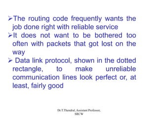
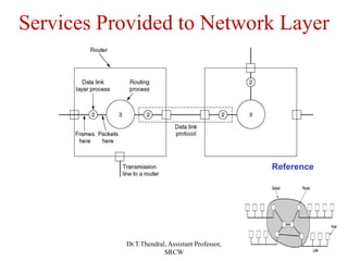
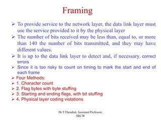
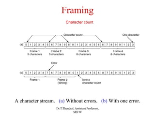
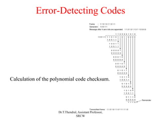
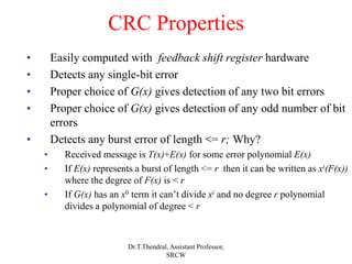
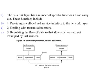
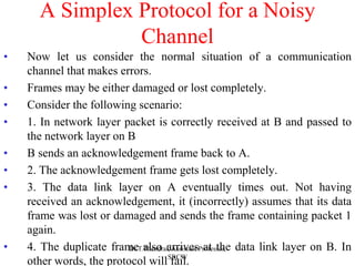
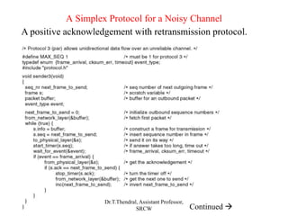
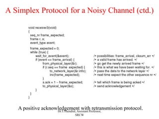
The Data Link Layer
Dr.T.Thendral, Assistant Professor,
SRCW
OBJECTIVE
• Data Link Layer Design Issues
• Error Detection and Correction
• Elementary Data Link Protocols
• Sliding Window Protocols
Dr.T.Thendral, Assistant Professor,
SRCW
Data Link Layer Design Issues
Dr.T.Thendral, Assistant Professor,
SRCW
Functions of the Data Link Layer
• Provide service interface to the network layer
• Dealing with transmission errors
• Regulating data flow
• Slow receivers not swamped by fast senders
Dr.T.Thendral, Assistant Professor,
SRCW
Functions of the Data Link Layer
Relationship between packets and frames.
Dr.T.Thendral, Assistant Professor,
SRCW
Services Provided to Network Layer
(a) Virtual Communication
(b) Actual Communication
Reference
Dr.T.Thendral, Assistant Professor,
SRCW
The data link layer can be designed to
offer various services
Three reasonable possibilities are
 Unacknowledged connectionless service
 Acknowledged connectionless service
 Acknowledged connection-oriented
service
Dr.T.Thendral, Assistant Professor,
SRCW
The routing code frequently wants the
job done right with reliable service
It does not want to be bothered too
often with packets that got lost on the
way
 Data link protocol, shown in the dotted
rectangle, to make unreliable
communication lines look perfect or, at
least, fairly good
Dr.T.Thendral, Assistant Professor,
SRCW
Services Provided to Network Layer
Reference
Dr.T.Thendral, Assistant Professor,
SRCW
Framing
 To provide service to the network layer, the data link layer must
use the service provided to it by the physical layer
 The number of bits received may be less than, equal to, or more
than 140 the number of bits transmitted, and they may have
different values.
 It is up to the data link layer to detect and, if necessary, correct
errors
 Since it is too risky to count on timing to mark the start and end of
each frame
 Four Methods:
 1. Character count
 2. Flag bytes with byte stuffing
 3. Starting and ending flags, with bit stuffing
 4. Physical layer coding violations
Dr.T.Thendral, Assistant Professor,
SRCW
Framing
A character stream. (a) Without errors. (b) With one error.
Character count
Dr.T.Thendral, Assistant Professor,
SRCW
• The second framing method gets around the problem of
resynchronization after an error by having each frame start
and end with special bytes
• Recent years most protocols have used the same byte,
called a flag byte, as both the starting and ending delimiter,
as FLAG.
• If the receiver ever loses synchronization, it can just search
for the flag byte to find the end of the current frame
• Two consecutive flag bytes indicate the end of one frame and
start of the next one.
Flag bytes with byte stuffing
Dr.T.Thendral, Assistant Professor,
SRCW
Framing
(a) A frame delimited by flag bytes.
(b) Four examples of byte sequences before and after stuffing.
ESCAPE BYTE (ESC)
Flag bytes with BYTE stuffing
Dr.T.Thendral, Assistant Professor,
SRCW
a) Each frame begins and ends with a special bit pattern, 01111110 (in
fact, a flag byte).
b) Whenever the sender's data link layer encounters five consecutive
1s in the data, it automatically stuffs a 0 bit into the outgoing bit
stream
Starting and ending flags, with BIT stuffing
Dr.T.Thendral, Assistant Professor,
SRCW
Framing
Bit stuffing
(a) The original data.
(b) The data as they appear on the line.
(c) The data as they are stored in receiver’s memory after destuffing.
Dr.T.Thendral, Assistant Professor,
SRCW
Error Detection and Correction
Error-Detecting Codes
•Parity bit
•Checksum
• https://www.youtube.com/watch?v=dbGJcinMJKM&t=0s
•Cyclic Redundancy Check Codes – CRC codes
• https://www.youtube.com/watch?v=PzNLmP5q8Ag
Error-Correcting Codes
•Hamming code
• https://www.youtube.com/watch?v=UNe3tF00gFQ
Dr.T.Thendral, Assistant Professor,
SRCW
Hamming Distance
• Some codes words are valid; others are invalid
• Hamming distance between two code words is number of bits
that must be flipped to change from one to the other
• If Hamming distance is d then d single bit errors needed to change one
word to the other
• Hamming distance of a code is the minimum Hamming
distance between two valid code words
• Detecting one single-bit error requires a distance 2 code; how
does this generalize?
• Correcting one single-bit error requires a distance 3 code; how
does this generalize?
Dr.T.Thendral, Assistant Professor,
SRCW
Parity Schemes
• Parity bits: choose a rule
• Even parity – each codeword has even number of 1’s
• Odd parity – each codeword has odd number of 1’s
• Always transmit according to the rule
• On receipt, if rule is violated, word is invalid
• Can also do “vertical parity” over whole block to achieve
single-bit error correction
Dr.T.Thendral, Assistant Professor,
SRCW
CRC Schemes
• CRC – Cyclic Redundancy Check or polynomial code
• Consider bits of a message to be coefficients of a polynomial
M(x)
• 1011 – 1x3 + 0x2 + 1x1 + 1x0
• Of course real messages will be much longer and hence of higher degree
• Agree on a small-degree generator polynomial G(x) of degree r
• Note: G(x) has r digits to the right of the leading 1, hence r+1 total
• Divide xrM(x) by G(x) using modulo 2 division (no carries or
borrows) getting the remainder polynomial R(x)
• Transmit T(x) = xrM(x) - R(x); note that this has remainder 0
when divided by G(x)
• Receiver rejects frame if the remainder it computers is not 0
Dr.T.Thendral, Assistant Professor,
SRCW
Error-Detecting Codes
Calculation of the polynomial code checksum.
Dr.T.Thendral, Assistant Professor,
SRCW
CRC Properties
• Easily computed with feedback shift register hardware
• Detects any single-bit error
• Proper choice of G(x) gives detection of any two bit errors
• Proper choice of G(x) gives detection of any odd number of bit
errors
• Detects any burst error of length <= r; Why?
• Received message is T(x)+E(x) for some error polynomial E(x)
• If E(x) represents a burst of length <= r then it can be written as xi(F(x))
where the degree of F(x) is < r
• If G(x) has an x0 term it can’t divide xi and no degree r polynomial
divides a polynomial of degree < r
Dr.T.Thendral, Assistant Professor,
SRCW
Elementary Data-link Protocols
a) https://www.youtube.com/watch?v=v5zT-tp9P_I
b) Elementary Data Link Protocols
c) Physical layer, data link layer, and network layer are independent
processes that communicate by passing messages back and forth
d) In many cases, the physical and data link layer processes will be
running on a processor inside a special network I/O chip and the
network layer code will be running on the main CPU
Dr.T.Thendral, Assistant Professor,
SRCW
a) The data link layer has a number of specific functions it can carry
out. These functions include
b) 1. Providing a well-defined service interface to the network layer.
c) 2. Dealing with transmission errors.
d) 3. Regulating the flow of data so that slow receivers are not
swamped by fast senders.
Dr.T.Thendral, Assistant Professor,
SRCW
Elementary Data Link Protocols
• An Unrestricted Simplex Protocol
• No buffer limits, no errors
• A Simplex Stop-and-Wait Protocol
• Add buffer limits
• A Simplex Protocol for a Noisy Channel
• Add channel errors
Dr.T.Thendral, Assistant Professor,
SRCW
Protocol Definitions
Continued 
Some definitions needed in the protocols to follow.
These are located in the file protocol.h.
Five data structures are defined there: boolean,
seq_nr, packet, frame_kind, and frame
Dr.T.Thendral, Assistant Professor,
SRCW
Protocol
Definitions
(ctd.)
Some definitions
needed in the
protocols to follow.
These are located in
the file protocol.h.
Dr.T.Thendral, Assistant Professor,
SRCW
• A frame is composed of four fields: kind, seq, ack, and info, the first
three of which contain control information and the last of which
may contain actual data to be transferred.
Dr.T.Thendral, Assistant Professor,
SRCW
An Unrestricted Simplex Protocol
• As an initial example we will consider a protocol that is as simple as
it can be.
• Data are transmitted in one direction only.
• Both the transmitting and receiving network layers are always
ready.
• Processing time can be ignored. Infinite buffer space is available.
• And best of all, the communication channel between the data link
layers never damages or loses frames.
• No sequence numbers or acknowledgements are used here, so
MAX_SEQ is not needed.
• The only event type possible is frame_arrival (i.e., the arrival of an
undamaged frame)
Dr.T.Thendral, Assistant Professor,
SRCW
Unrestricted
Simplex
Protocol
Dr.T.Thendral, Assistant Professor,
SRCW
A Simplex Stop-and-Wait Protocol
• The communication channel is still assumed to be error free
however, and the data traffic is still simplex.
• The main problem we have to deal with here is how to prevent the
sender from flooding the receiver with data faster than the latter is
able to process them
• Protocols in which the sender sends one frame and then waits for an
acknowledgement before proceeding are called stop-and-wait
• The only difference between receiver1 and receiver2 is that after
delivering a packet to the network layer, receiver2 sends an
acknowledgement frame back to the sender before entering the wait
loop again.
Dr.T.Thendral, Assistant Professor,
SRCW
Simplex
Stop-and-
Wait
Protocol
Dr.T.Thendral, Assistant Professor,
SRCW
A Simplex Protocol for a Noisy
Channel
• Now let us consider the normal situation of a communication
channel that makes errors.
• Frames may be either damaged or lost completely.
• Consider the following scenario:
• 1. In network layer packet is correctly received at B and passed to
the network layer on B
• B sends an acknowledgement frame back to A.
• 2. The acknowledgement frame gets lost completely.
• 3. The data link layer on A eventually times out. Not having
received an acknowledgement, it (incorrectly) assumes that its data
frame was lost or damaged and sends the frame containing packet 1
again.
• 4. The duplicate frame also arrives at the data link layer on B. In
other words, the protocol will fail.
Dr.T.Thendral, Assistant Professor,
SRCW
A Simplex Protocol for a Noisy Channel
A positive acknowledgement with retransmission protocol.
Continued 
Dr.T.Thendral, Assistant Professor,
SRCW
A Simplex Protocol for a Noisy Channel (ctd.)
A positive acknowledgement with retransmission protocol.
Dr.T.Thendral, Assistant Professor,
SRCW
Sliding Window Protocols
• In the previous protocols, data frames were transmitted in one
direction only. In most practical situations, there is a need for
transmitting data in both directions
• One way of achieving full-duplex data transmission is to have two
separate communication channels and use each one for simplex data
traffic
Dr.T.Thendral, Assistant Professor,
SRCW
Sliding Window Protocols
• Why?
• Efficiency – bandwidth*delay product
• Efficiency – when errors occur
• A One-Bit Sliding Window Protocol
• A Protocol Using Go Back N
• A Protocol Using Selective Repeat
Dr.T.Thendral, Assistant Professor,
SRCW
Sliding Window Protocols
A sliding window of size 1, with a 3-bit sequence number
• Initially
• After the first frame has been sent
• After the first frame has been received
• After the first acknowledgement has been received
Dr.T.Thendral, Assistant Professor,
SRCW
A One-Bit Sliding Window Protocol
Continued 
Dr.T.Thendral, Assistant Professor,
SRCW
A One-Bit Sliding Window Protocol (ctd.)
Dr.T.Thendral, Assistant Professor,
SRCW
A One-Bit Sliding Window Protocol (2)
Two scenarios for protocol 4. (a) Normal case. (b) Abnormal
case. The notation is (seq, ack, packet number). An asterisk
indicates where a network layer accepts a packet.
Dr.T.Thendral, Assistant Professor,
SRCW
A Protocol Using Go Back N
Pipelining and error recovery. Effect on an error when
(a) Receiver’s window size is 1.
(b) Receiver’s window size is large.
Dr.T.Thendral, Assistant Professor,
SRCW
• Frames 0 and 1 are correctly received and acknowledged.
• Frame 2, however, is damaged or lost.
• The sender, unaware of this problem, continues to send frames until
the timer for frame 2 expires.
• Then it backs up to frame 2 and starts all over with it, sending 2, 3,
4, etc. all over again.
Dr.T.Thendral, Assistant Professor,
SRCW
Sliding
Window
Protocol
Using Go
Back N
Continued 
Dr.T.Thendral, Assistant Professor,
SRCW
Sliding Window Protocol Using Go Back N
Continued 
Dr.T.Thendral, Assistant Professor,
SRCW
Sliding Window Protocol Using Go Back N
Continued 
Dr.T.Thendral, Assistant Professor,
SRCW
Sliding Window Protocol Using Go Back N
Dr.T.Thendral, Assistant Professor,
SRCW
Sliding Window Protocol Using Go Back N (2)
Simulation of multiple timers in software.
Dr.T.Thendral, Assistant Professor,
SRCW
A Sliding Window Protocol Using Selective Repeat
Continued 
Dr.T.Thendral, Assistant Professor,
SRCW
Continued 
A Sliding Window Protocol Using Selective Repeat (2)
Dr.T.Thendral, Assistant Professor,
SRCW
A Sliding Window Protocol Using Selective Repeat (3)
Continued 
Dr.T.Thendral, Assistant Professor,
SRCW
A Sliding Window Protocol Using Selective Repeat (4)
Dr.T.Thendral, Assistant Professor,
SRCW
A Sliding Window Protocol Using Selective Repeat (5)
(a) Initial situation with a window size seven.
(b) After seven frames sent and received, but not acknowledged.
(c) Initial situation with a window size of four.
(d) After four frames sent and received, but not acknowledged.
Dr.T.Thendral, Assistant Professor,
SRCW

DATA-LINK LAYER.ppt

  • 1.
    The Data LinkLayer Dr.T.Thendral, Assistant Professor, SRCW
  • 2.
    OBJECTIVE • Data LinkLayer Design Issues • Error Detection and Correction • Elementary Data Link Protocols • Sliding Window Protocols Dr.T.Thendral, Assistant Professor, SRCW
  • 3.
    Data Link LayerDesign Issues Dr.T.Thendral, Assistant Professor, SRCW
  • 4.
    Functions of theData Link Layer • Provide service interface to the network layer • Dealing with transmission errors • Regulating data flow • Slow receivers not swamped by fast senders Dr.T.Thendral, Assistant Professor, SRCW
  • 5.
    Functions of theData Link Layer Relationship between packets and frames. Dr.T.Thendral, Assistant Professor, SRCW
  • 6.
    Services Provided toNetwork Layer (a) Virtual Communication (b) Actual Communication Reference Dr.T.Thendral, Assistant Professor, SRCW
  • 7.
    The data linklayer can be designed to offer various services Three reasonable possibilities are  Unacknowledged connectionless service  Acknowledged connectionless service  Acknowledged connection-oriented service Dr.T.Thendral, Assistant Professor, SRCW
  • 8.
    The routing codefrequently wants the job done right with reliable service It does not want to be bothered too often with packets that got lost on the way  Data link protocol, shown in the dotted rectangle, to make unreliable communication lines look perfect or, at least, fairly good Dr.T.Thendral, Assistant Professor, SRCW
  • 9.
    Services Provided toNetwork Layer Reference Dr.T.Thendral, Assistant Professor, SRCW
  • 10.
    Framing  To provideservice to the network layer, the data link layer must use the service provided to it by the physical layer  The number of bits received may be less than, equal to, or more than 140 the number of bits transmitted, and they may have different values.  It is up to the data link layer to detect and, if necessary, correct errors  Since it is too risky to count on timing to mark the start and end of each frame  Four Methods:  1. Character count  2. Flag bytes with byte stuffing  3. Starting and ending flags, with bit stuffing  4. Physical layer coding violations Dr.T.Thendral, Assistant Professor, SRCW
  • 11.
    Framing A character stream.(a) Without errors. (b) With one error. Character count Dr.T.Thendral, Assistant Professor, SRCW
  • 12.
    • The secondframing method gets around the problem of resynchronization after an error by having each frame start and end with special bytes • Recent years most protocols have used the same byte, called a flag byte, as both the starting and ending delimiter, as FLAG. • If the receiver ever loses synchronization, it can just search for the flag byte to find the end of the current frame • Two consecutive flag bytes indicate the end of one frame and start of the next one. Flag bytes with byte stuffing Dr.T.Thendral, Assistant Professor, SRCW
  • 13.
    Framing (a) A framedelimited by flag bytes. (b) Four examples of byte sequences before and after stuffing. ESCAPE BYTE (ESC) Flag bytes with BYTE stuffing Dr.T.Thendral, Assistant Professor, SRCW
  • 14.
    a) Each framebegins and ends with a special bit pattern, 01111110 (in fact, a flag byte). b) Whenever the sender's data link layer encounters five consecutive 1s in the data, it automatically stuffs a 0 bit into the outgoing bit stream Starting and ending flags, with BIT stuffing Dr.T.Thendral, Assistant Professor, SRCW
  • 15.
    Framing Bit stuffing (a) Theoriginal data. (b) The data as they appear on the line. (c) The data as they are stored in receiver’s memory after destuffing. Dr.T.Thendral, Assistant Professor, SRCW
  • 16.
    Error Detection andCorrection Error-Detecting Codes •Parity bit •Checksum • https://www.youtube.com/watch?v=dbGJcinMJKM&t=0s •Cyclic Redundancy Check Codes – CRC codes • https://www.youtube.com/watch?v=PzNLmP5q8Ag Error-Correcting Codes •Hamming code • https://www.youtube.com/watch?v=UNe3tF00gFQ Dr.T.Thendral, Assistant Professor, SRCW
  • 17.
    Hamming Distance • Somecodes words are valid; others are invalid • Hamming distance between two code words is number of bits that must be flipped to change from one to the other • If Hamming distance is d then d single bit errors needed to change one word to the other • Hamming distance of a code is the minimum Hamming distance between two valid code words • Detecting one single-bit error requires a distance 2 code; how does this generalize? • Correcting one single-bit error requires a distance 3 code; how does this generalize? Dr.T.Thendral, Assistant Professor, SRCW
  • 18.
    Parity Schemes • Paritybits: choose a rule • Even parity – each codeword has even number of 1’s • Odd parity – each codeword has odd number of 1’s • Always transmit according to the rule • On receipt, if rule is violated, word is invalid • Can also do “vertical parity” over whole block to achieve single-bit error correction Dr.T.Thendral, Assistant Professor, SRCW
  • 19.
    CRC Schemes • CRC– Cyclic Redundancy Check or polynomial code • Consider bits of a message to be coefficients of a polynomial M(x) • 1011 – 1x3 + 0x2 + 1x1 + 1x0 • Of course real messages will be much longer and hence of higher degree • Agree on a small-degree generator polynomial G(x) of degree r • Note: G(x) has r digits to the right of the leading 1, hence r+1 total • Divide xrM(x) by G(x) using modulo 2 division (no carries or borrows) getting the remainder polynomial R(x) • Transmit T(x) = xrM(x) - R(x); note that this has remainder 0 when divided by G(x) • Receiver rejects frame if the remainder it computers is not 0 Dr.T.Thendral, Assistant Professor, SRCW
  • 20.
    Error-Detecting Codes Calculation ofthe polynomial code checksum. Dr.T.Thendral, Assistant Professor, SRCW
  • 21.
    CRC Properties • Easilycomputed with feedback shift register hardware • Detects any single-bit error • Proper choice of G(x) gives detection of any two bit errors • Proper choice of G(x) gives detection of any odd number of bit errors • Detects any burst error of length <= r; Why? • Received message is T(x)+E(x) for some error polynomial E(x) • If E(x) represents a burst of length <= r then it can be written as xi(F(x)) where the degree of F(x) is < r • If G(x) has an x0 term it can’t divide xi and no degree r polynomial divides a polynomial of degree < r Dr.T.Thendral, Assistant Professor, SRCW
  • 22.
    Elementary Data-link Protocols a)https://www.youtube.com/watch?v=v5zT-tp9P_I b) Elementary Data Link Protocols c) Physical layer, data link layer, and network layer are independent processes that communicate by passing messages back and forth d) In many cases, the physical and data link layer processes will be running on a processor inside a special network I/O chip and the network layer code will be running on the main CPU Dr.T.Thendral, Assistant Professor, SRCW
  • 23.
    a) The datalink layer has a number of specific functions it can carry out. These functions include b) 1. Providing a well-defined service interface to the network layer. c) 2. Dealing with transmission errors. d) 3. Regulating the flow of data so that slow receivers are not swamped by fast senders. Dr.T.Thendral, Assistant Professor, SRCW
  • 24.
    Elementary Data LinkProtocols • An Unrestricted Simplex Protocol • No buffer limits, no errors • A Simplex Stop-and-Wait Protocol • Add buffer limits • A Simplex Protocol for a Noisy Channel • Add channel errors Dr.T.Thendral, Assistant Professor, SRCW
  • 25.
    Protocol Definitions Continued  Somedefinitions needed in the protocols to follow. These are located in the file protocol.h. Five data structures are defined there: boolean, seq_nr, packet, frame_kind, and frame Dr.T.Thendral, Assistant Professor, SRCW
  • 26.
    Protocol Definitions (ctd.) Some definitions needed inthe protocols to follow. These are located in the file protocol.h. Dr.T.Thendral, Assistant Professor, SRCW
  • 27.
    • A frameis composed of four fields: kind, seq, ack, and info, the first three of which contain control information and the last of which may contain actual data to be transferred. Dr.T.Thendral, Assistant Professor, SRCW
  • 28.
    An Unrestricted SimplexProtocol • As an initial example we will consider a protocol that is as simple as it can be. • Data are transmitted in one direction only. • Both the transmitting and receiving network layers are always ready. • Processing time can be ignored. Infinite buffer space is available. • And best of all, the communication channel between the data link layers never damages or loses frames. • No sequence numbers or acknowledgements are used here, so MAX_SEQ is not needed. • The only event type possible is frame_arrival (i.e., the arrival of an undamaged frame) Dr.T.Thendral, Assistant Professor, SRCW
  • 29.
  • 30.
    A Simplex Stop-and-WaitProtocol • The communication channel is still assumed to be error free however, and the data traffic is still simplex. • The main problem we have to deal with here is how to prevent the sender from flooding the receiver with data faster than the latter is able to process them • Protocols in which the sender sends one frame and then waits for an acknowledgement before proceeding are called stop-and-wait • The only difference between receiver1 and receiver2 is that after delivering a packet to the network layer, receiver2 sends an acknowledgement frame back to the sender before entering the wait loop again. Dr.T.Thendral, Assistant Professor, SRCW
  • 31.
  • 32.
    A Simplex Protocolfor a Noisy Channel • Now let us consider the normal situation of a communication channel that makes errors. • Frames may be either damaged or lost completely. • Consider the following scenario: • 1. In network layer packet is correctly received at B and passed to the network layer on B • B sends an acknowledgement frame back to A. • 2. The acknowledgement frame gets lost completely. • 3. The data link layer on A eventually times out. Not having received an acknowledgement, it (incorrectly) assumes that its data frame was lost or damaged and sends the frame containing packet 1 again. • 4. The duplicate frame also arrives at the data link layer on B. In other words, the protocol will fail. Dr.T.Thendral, Assistant Professor, SRCW
  • 33.
    A Simplex Protocolfor a Noisy Channel A positive acknowledgement with retransmission protocol. Continued  Dr.T.Thendral, Assistant Professor, SRCW
  • 34.
    A Simplex Protocolfor a Noisy Channel (ctd.) A positive acknowledgement with retransmission protocol. Dr.T.Thendral, Assistant Professor, SRCW
  • 35.
    Sliding Window Protocols •In the previous protocols, data frames were transmitted in one direction only. In most practical situations, there is a need for transmitting data in both directions • One way of achieving full-duplex data transmission is to have two separate communication channels and use each one for simplex data traffic Dr.T.Thendral, Assistant Professor, SRCW
  • 36.
    Sliding Window Protocols •Why? • Efficiency – bandwidth*delay product • Efficiency – when errors occur • A One-Bit Sliding Window Protocol • A Protocol Using Go Back N • A Protocol Using Selective Repeat Dr.T.Thendral, Assistant Professor, SRCW
  • 37.
    Sliding Window Protocols Asliding window of size 1, with a 3-bit sequence number • Initially • After the first frame has been sent • After the first frame has been received • After the first acknowledgement has been received Dr.T.Thendral, Assistant Professor, SRCW
  • 38.
    A One-Bit SlidingWindow Protocol Continued  Dr.T.Thendral, Assistant Professor, SRCW
  • 39.
    A One-Bit SlidingWindow Protocol (ctd.) Dr.T.Thendral, Assistant Professor, SRCW
  • 40.
    A One-Bit SlidingWindow Protocol (2) Two scenarios for protocol 4. (a) Normal case. (b) Abnormal case. The notation is (seq, ack, packet number). An asterisk indicates where a network layer accepts a packet. Dr.T.Thendral, Assistant Professor, SRCW
  • 41.
    A Protocol UsingGo Back N Pipelining and error recovery. Effect on an error when (a) Receiver’s window size is 1. (b) Receiver’s window size is large. Dr.T.Thendral, Assistant Professor, SRCW
  • 42.
    • Frames 0and 1 are correctly received and acknowledged. • Frame 2, however, is damaged or lost. • The sender, unaware of this problem, continues to send frames until the timer for frame 2 expires. • Then it backs up to frame 2 and starts all over with it, sending 2, 3, 4, etc. all over again. Dr.T.Thendral, Assistant Professor, SRCW
  • 43.
    Sliding Window Protocol Using Go Back N Continued Dr.T.Thendral, Assistant Professor, SRCW
  • 44.
    Sliding Window ProtocolUsing Go Back N Continued  Dr.T.Thendral, Assistant Professor, SRCW
  • 45.
    Sliding Window ProtocolUsing Go Back N Continued  Dr.T.Thendral, Assistant Professor, SRCW
  • 46.
    Sliding Window ProtocolUsing Go Back N Dr.T.Thendral, Assistant Professor, SRCW
  • 47.
    Sliding Window ProtocolUsing Go Back N (2) Simulation of multiple timers in software. Dr.T.Thendral, Assistant Professor, SRCW
  • 48.
    A Sliding WindowProtocol Using Selective Repeat Continued  Dr.T.Thendral, Assistant Professor, SRCW
  • 49.
    Continued  A SlidingWindow Protocol Using Selective Repeat (2) Dr.T.Thendral, Assistant Professor, SRCW
  • 50.
    A Sliding WindowProtocol Using Selective Repeat (3) Continued  Dr.T.Thendral, Assistant Professor, SRCW
  • 51.
    A Sliding WindowProtocol Using Selective Repeat (4) Dr.T.Thendral, Assistant Professor, SRCW
  • 52.
    A Sliding WindowProtocol Using Selective Repeat (5) (a) Initial situation with a window size seven. (b) After seven frames sent and received, but not acknowledged. (c) Initial situation with a window size of four. (d) After four frames sent and received, but not acknowledged. Dr.T.Thendral, Assistant Professor, SRCW