Application of Unified Power Flow Controller in Nigeria Power System for Impr...
APS poster_dip_ver1
1. Role of Demand-side Options in Improving
Stability of Autonomic Power System
Background and Motivation
.
Contact details: d.chakravorty12@imperial.ac.uk
• Effective inertia and short-circuit level of Great Britain (GB)
transmission system would reduce significantly in future due to
large proportion of non-synchronous generation (NSG). (National
Grid System Operability Framework 2014)
• Following large loss of infeed system may experience high rate of
change (RoCoF) of grid frequency and deeper frequency nadir.
• High RoCoF may lead to undesirable mains protection relay
tripping resulting in prolonged frequency depression.
• Containing grid frequency and voltage variations within
permissible limits would be very challenging.
• Rapid response from loads could be crucial in such situations to
ensure secure operation of the system.
• Developing combined transmission-distribution network simulation
framework to make studies more comprehensive and realistic.
• Using recorded power profiles at MV substations for load
disaggregation and thus quantifying the power reserve on an hourly
(or half-hourly) basis.
The Autonomic Power System: An EPSRC Grand Challenge in Energy Networks
Researcher Diptargha Chakravorty
Supervisor Dr. Balarko Chaudhuri, Prof Goran Strbac
Control and Power Group, Electrical Engineering Department
Project code AP08
APS stream Active Participation
of Consumers
Research Objective
• Investigate the availability of fast short-term power reserve
(FSPR) from different types of loads to aid voltage regulation
and/or collectively contribute to inertial and primary frequency
control.
• Estimate the total FSPR offered by suitable industrial and service
sector loads across the Great Britain system. (based on annual
energy consumption data from Department of Energy and Climate
Change 2013, UK)
• Study aggregated impact of FSPR in stabilization of grid
frequency and/or maintain bus voltages within acceptable limit
after large loss of infeed.
• Effectively mitigate voltage problems due to photovoltaic (PV)
generation and electric vehicle (EV) charging in low/medium
voltage (LV/MV) distribution networks.
Smart Load
• Alongside the duty-cycle control of thermostatic loads (e.g.
refrigerators), other non-critical voltage-sensitive loads (e.g.
heaters, some lighting loads etc.) could be made to contribute to
FSPR by decoupling them from the supply mains through part-
rated power electronic interfaces. This way voltage across such
loads and hence, their power consumption, can be controlled over
a much wider range in the short-term.
• Such a load together with its power electronic interface forms a so
called ‘smart load’.
• Smart load comprises of a controlled voltage source (Electric
Spring) in series with a non-critical load, as shown in Fig. 1. The
injected series voltage (VESES) is controlled to regulate the mains
voltage while allowing the voltage across the non-critical load
(VNC) and consequently its active power consumption to vary,
thereby, collectively providing a short term power reserve.
• Role of drive-controlled motors has also been considered for
providing FSPR.
Converter #1
VES ES
PES = VESIcosES
QES = VESIsinES
VC
Supply mains
I0
PSL=PNC PES
QSL=QNC QES
Converter #2
Vdc and Q(=0) control VES and ES control
PES ≈ VESIcosES
C
VNC
I0
Non-critical load
PNC=PNC0(VNC/VNC0)kpv
QNC=QNC0(VNC/VNC0)kqv
Fig.1: Smart load configuration
Rapid Frequency Response in GB
1. TEST NETWORK
IFA
1
IFA
2
Z 3Z 2
Z 1
Z 4 Z 5
Z 6 Z 7
Z
10
Z
10
Z
11
Z 9Z 8
Z
12
Z
13
Z
14A
Z
14
Z
15
Z
16Z
17
Z
18
Z
20
Z
21
Z
19
Z
22
Z
23
Z
24
Z
16
Z
25A
Z
25
Z
26
Z
27E
Z
27W
Z
S9
Z
28
Z
29
Z
30 Z
31
Z
33
Z
32
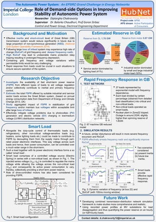
• 37 loads represented by
exponential model with frequency
dependence.
• Each load divided by certain
percentage (obtained from detailed
load classification) into critical and
non-critical loads.
• Non-critical loads operated as
smart loads.
• Nuclear plant in Zone22 tripped.
Outage is around 2GW, slightly
higher than spinning reserve of
1.8GW.
2. SIMULATION RESULTS
Fig. 2: 67 machine GB reduced
model
20 25 30 35
49.2
49.4
49.6
49.8
50
Time(sec)
Frequency(Hz)
(a) present inertia
noSL
SL
20 25 30 35
49.2
49.4
49.6
49.8
50
Time(sec)
Frequency(Hz)
(b) future low inertia
20 22.5 25
-0.6
-0.4
-0.2
0
0.2
-0.58
-0.23
Time(sec)
RoCoF(Hz/sec)
(c) present inertia
20 22.5 25
-1
-0.8
-0.6
-0.4
-0.2
0
0.2
-0.95
-0.29
Time(sec)
RoCoF(Hz/sec)
(d) future low inertia
• Smart loads
provide
effective rapid
frequency
response.
• Two scenarios
considered
(a) present inertia
(b) future low
inertia.
• In future, similar disturbance will result in more severe frequency
excursion and RoCoF.
• FSPR effectively arrests frequency nadir and significantly improve
RoCoF.
Fig. 3: Dynamic variation of frequency (at bus 22) and
RoCoF (with 100ms moving window)
Estimated Reserve in GB
Future Work
Space
heating
20%
Cooling/v
entilation
13%
Large
motor
26%
Small
motor
26%
Compres
sed air
15%
Drying/sep
aration
13.80%
Water
heating
11.21%
Fluoresce
nt light
27.46%
Halogen
light
43.14%
Mercury
HP light
0.40%
Sodium
HP light
3.96%
Sodium LP
light
0.04%
Other
4.39%
Reserve from SL 1.76 GW Reserve from motor 0.87 GW
• Industrial sector dominated
by small and large industrial
motor load (32%).
• Service sector dominated by
lighting load (41%).