SlideShare a Scribd company logo
1 of 9
SOUTH DAKOTA STATE UNIVERSITY
ANSYS Final Project
Luggage Tote for a Manual Wheelchair
Danard Higgs, Ashim, Dahal, Sam Gould
5/4/2012
Course: ME 417/517
Professor: Dr. ZhongHu
Background / Purpose
Two of the group members, Danard and Sam, were working on a mechanical engineering
senior design project requiring some finite element analysis. The goal of the senior design
project was to design a luggage tote for a manual wheelchair as shown in Figure 1. The tote was
designed to hold 30 lbs with a safety factor of 2. The tote frame was constructed entirely out of
6061 T-6 aluminum alloy. The FEA was performed in ANSYS and involved finding the
maximum von Mises stress and deflection of the tote under various degrees of loading. The load
was applied at the corner of the tote furthest from the mounting pole (a.k.a. the “mast”) to
produce the worst-case deflection and internal stress.
Figure 1: Luggage Tote for a Manual Wheelchair
Deflection
To simulate the presence of the wheelchair and its rigidity, we simply created a 2-in
boundary condition which fixed the mast in the x, y, and z direction at the bottom of the mast.
Lastly, a 30-lb force over 91 nodes was applied in the downward (negative y-axis direction) as
shown in Figure 2.
Figure 2: Boundary Conditions and Load
For our FEA deflection analysis, there was a maximum deflection of 1.63 inches. This
maximum deflection occurred mostly at the point where the load was applied which was
expected. As the Figure 3 below shows, the deflection is distributed evenly throughout the mast.
The most distributed load deflection occurs along the front and left angle bar whilst the least
amount occurs on the right and back angle bar.
Figure 3: Deflection Only, 30-lb Load
The next three figures show the deflection with respect to the initial position of the tote at
various view angles. The black lines arranged in a grid represent the tote in its unloaded position
and the colored solid part shows the tote when it is loaded. The deflection is again 1.63 inches.
Figure 4: Deflection + Initial Position, 30-lb Load, View 1
Figure 5: Deflection + Initial Position, 30-lb Load, View 2
The deflection shown in the above three figures (but especially evident in Figure 6) is
exaggerated from real life due to differences in the area covered by the applied distributed load.
In ANSYS, we were able to apply a load on a smaller area toward the far corner, whereas in an
experimental setting the load was distributed more toward the middle of the tote.
In order to compare the behavior of the tote in ANSYS to that of the real-life
experimental setting, loads were applied from 0 – 60 lbs in 5-lb increments in ANSYS and the
deflections were plotted. This was compared to the same set of data collected experimentally.
These deflection curves are illustrated in Figure 7. As one can see, both the ANSYS and
experimental curves follow a close-to-linear pattern. However, the curve of the experimental
deflection has a lesser slope. Once again, the difference here is probably due to how the load was
distributed in ANSYS versus how it was able to be distributed in real life. In the experimental
setting, the weight was distributed closer to the center of the tote rather than the far edge, which
would result in lesser deflection for any given amount of weight.
Figure 6: Deflection + Initial Position, 30-lb Load, View 3
Figure 7: Deflection Curves
Stress
The stress that was exerted by the 30-lb load is shown in the figures below at different
view angles. The yield stress for the 6061 T-6 aluminum frame was 24 ksi. The most common
level of von Mises stress exerted on the tote was about 8.25 ksi, which provided a safety factor of
2.9. This exceeds the desired safety factor 2.0, which is great but may be slightly too high for this
application. However, this prevents a careless user of the product from doing harm to the tote.
0
0.5
1
1.5
2
2.5
3
3.5
0 10 20 30 40 50 60 70
Deflection(in)
Weight (lb)
ANSYS
Experimental
Figure 8: Von Mises Stresses, View 1
Figure 9: Von Mises Stresses, View 2
The maximum stress for this tote was 37.14 ksi, which admittedly exceeds the yield
stress. This means that if the tote was to fail, it would fail in this particular area. The area where
the maximum stress occurs can be seen in Figure 10 in the small area shown below. However, it
is speculated that the maximum stress is actually less than 37.14 ksi and the reason for such a
high calculated stress is due to limitations in the finite element grid size. In an experimental
setting, the deformation of the tote frame is completely elastic even with twice the load
experienced in ANSYS—that is, 60 lbs.
Figure 10: Location of Maximum Stress

More Related Content

What's hot

What's hot (20)

Eccetric columns
Eccetric columnsEccetric columns
Eccetric columns
 
FEW BASIC CONCEPT OF STRENGTH OF MATERIALS
FEW BASIC CONCEPT OF STRENGTH OF MATERIALSFEW BASIC CONCEPT OF STRENGTH OF MATERIALS
FEW BASIC CONCEPT OF STRENGTH OF MATERIALS
 
10 columns
10 columns10 columns
10 columns
 
Simple stress and strains
Simple stress and strainsSimple stress and strains
Simple stress and strains
 
10 columns
10 columns10 columns
10 columns
 
Buckling test engt110
Buckling test engt110Buckling test engt110
Buckling test engt110
 
Mm210(2)
Mm210(2)Mm210(2)
Mm210(2)
 
Simpale stress and simple strain
Simpale stress and simple strainSimpale stress and simple strain
Simpale stress and simple strain
 
Lec8 buckling v2_1
Lec8 buckling v2_1Lec8 buckling v2_1
Lec8 buckling v2_1
 
Strength of Materials
Strength of MaterialsStrength of Materials
Strength of Materials
 
5 beams
5 beams5 beams
5 beams
 
Buckling and tension field beam for aerospace structures
Buckling and tension field beam for aerospace structuresBuckling and tension field beam for aerospace structures
Buckling and tension field beam for aerospace structures
 
151 dem303 ien00973_1600_98_chap 1 part 1
151 dem303 ien00973_1600_98_chap 1 part 1151 dem303 ien00973_1600_98_chap 1 part 1
151 dem303 ien00973_1600_98_chap 1 part 1
 
Bearing stress
Bearing stressBearing stress
Bearing stress
 
Structures and Materials- Section 3 Stress-Strain Relationships
Structures and Materials- Section 3 Stress-Strain RelationshipsStructures and Materials- Section 3 Stress-Strain Relationships
Structures and Materials- Section 3 Stress-Strain Relationships
 
Mechanics of materials
Mechanics of materialsMechanics of materials
Mechanics of materials
 
Simple stresses and strain
Simple stresses and strainSimple stresses and strain
Simple stresses and strain
 
Strength 1
Strength 1Strength 1
Strength 1
 
Mechanics of solids 1 lecture-1
Mechanics of solids 1 lecture-1Mechanics of solids 1 lecture-1
Mechanics of solids 1 lecture-1
 
7 stress transformations
7 stress transformations7 stress transformations
7 stress transformations
 

Viewers also liked

Unidad 8 y 9 historia universal III
Unidad 8 y 9 historia universal IIIUnidad 8 y 9 historia universal III
Unidad 8 y 9 historia universal IIIGerardo Bautista
 
Hojas de calculo
Hojas de calculoHojas de calculo
Hojas de calculopaulina2405
 
cómo crear un blog
cómo crear un blogcómo crear un blog
cómo crear un blogmartavillav
 
Tips for making powerpoint slide
Tips for making powerpoint slideTips for making powerpoint slide
Tips for making powerpoint slideMostafiz Chowdhury
 
D2-Sole-Trader-No-VAT
D2-Sole-Trader-No-VATD2-Sole-Trader-No-VAT
D2-Sole-Trader-No-VATDave carr
 
Actividad de aprendizaje 11 diseño y aplicación de materiales, medios y recur...
Actividad de aprendizaje 11 diseño y aplicación de materiales, medios y recur...Actividad de aprendizaje 11 diseño y aplicación de materiales, medios y recur...
Actividad de aprendizaje 11 diseño y aplicación de materiales, medios y recur...Tebam12
 
Actividad de aprendizaje 7 determinación de competencias y contenidos a desar...
Actividad de aprendizaje 7 determinación de competencias y contenidos a desar...Actividad de aprendizaje 7 determinación de competencias y contenidos a desar...
Actividad de aprendizaje 7 determinación de competencias y contenidos a desar...Tebam12
 
Diapositivadelosdelitosinformaticos
DiapositivadelosdelitosinformaticosDiapositivadelosdelitosinformaticos
Diapositivadelosdelitosinformaticosbartolomeuladech
 
Crane 2013 slideshow
Crane 2013 slideshowCrane 2013 slideshow
Crane 2013 slideshowJose
 
Actividad de aprendizaje 2 el contexto escolar de los estudiantes y el rol do...
Actividad de aprendizaje 2 el contexto escolar de los estudiantes y el rol do...Actividad de aprendizaje 2 el contexto escolar de los estudiantes y el rol do...
Actividad de aprendizaje 2 el contexto escolar de los estudiantes y el rol do...Tebam12
 
El acoso sexual en las redes sociales
El acoso sexual en las redes socialesEl acoso sexual en las redes sociales
El acoso sexual en las redes socialesXel Ari Hernàndez
 
Origo Solutions on LittleBits project
Origo Solutions on LittleBits projectOrigo Solutions on LittleBits project
Origo Solutions on LittleBits projectDanilo Salazar Ramos
 
Actividad de aprendizaje 6 foro planteamiento del diseño de estrategias de ap...
Actividad de aprendizaje 6 foro planteamiento del diseño de estrategias de ap...Actividad de aprendizaje 6 foro planteamiento del diseño de estrategias de ap...
Actividad de aprendizaje 6 foro planteamiento del diseño de estrategias de ap...Tebam12
 
Como publicar en wordpress
Como publicar en wordpressComo publicar en wordpress
Como publicar en wordpresspaulyabadabad
 
Générer plus de prestations juridiques pour les avocats PI
Générer plus de prestations juridiques pour les avocats PI Générer plus de prestations juridiques pour les avocats PI
Générer plus de prestations juridiques pour les avocats PI SparkUp
 
Ethical challenges in research on the well-being of children and young people
Ethical challenges in research on the  well-being of children and young peopleEthical challenges in research on the  well-being of children and young people
Ethical challenges in research on the well-being of children and young peopleYoung Lives Oxford
 

Viewers also liked (20)

Unidad 8 y 9 historia universal III
Unidad 8 y 9 historia universal IIIUnidad 8 y 9 historia universal III
Unidad 8 y 9 historia universal III
 
Hojas de calculo
Hojas de calculoHojas de calculo
Hojas de calculo
 
cómo crear un blog
cómo crear un blogcómo crear un blog
cómo crear un blog
 
Tips for making powerpoint slide
Tips for making powerpoint slideTips for making powerpoint slide
Tips for making powerpoint slide
 
Tabla conceptos
Tabla conceptosTabla conceptos
Tabla conceptos
 
D2-Sole-Trader-No-VAT
D2-Sole-Trader-No-VATD2-Sole-Trader-No-VAT
D2-Sole-Trader-No-VAT
 
Proyecto técnico
Proyecto técnicoProyecto técnico
Proyecto técnico
 
Actividad de aprendizaje 11 diseño y aplicación de materiales, medios y recur...
Actividad de aprendizaje 11 diseño y aplicación de materiales, medios y recur...Actividad de aprendizaje 11 diseño y aplicación de materiales, medios y recur...
Actividad de aprendizaje 11 diseño y aplicación de materiales, medios y recur...
 
Actividad de aprendizaje 7 determinación de competencias y contenidos a desar...
Actividad de aprendizaje 7 determinación de competencias y contenidos a desar...Actividad de aprendizaje 7 determinación de competencias y contenidos a desar...
Actividad de aprendizaje 7 determinación de competencias y contenidos a desar...
 
Unidad71
Unidad71Unidad71
Unidad71
 
Diapositivadelosdelitosinformaticos
DiapositivadelosdelitosinformaticosDiapositivadelosdelitosinformaticos
Diapositivadelosdelitosinformaticos
 
Crane 2013 slideshow
Crane 2013 slideshowCrane 2013 slideshow
Crane 2013 slideshow
 
Actividad de aprendizaje 2 el contexto escolar de los estudiantes y el rol do...
Actividad de aprendizaje 2 el contexto escolar de los estudiantes y el rol do...Actividad de aprendizaje 2 el contexto escolar de los estudiantes y el rol do...
Actividad de aprendizaje 2 el contexto escolar de los estudiantes y el rol do...
 
El acoso sexual en las redes sociales
El acoso sexual en las redes socialesEl acoso sexual en las redes sociales
El acoso sexual en las redes sociales
 
Origo Solutions on LittleBits project
Origo Solutions on LittleBits projectOrigo Solutions on LittleBits project
Origo Solutions on LittleBits project
 
Circular horario verano 2015
Circular horario verano 2015Circular horario verano 2015
Circular horario verano 2015
 
Actividad de aprendizaje 6 foro planteamiento del diseño de estrategias de ap...
Actividad de aprendizaje 6 foro planteamiento del diseño de estrategias de ap...Actividad de aprendizaje 6 foro planteamiento del diseño de estrategias de ap...
Actividad de aprendizaje 6 foro planteamiento del diseño de estrategias de ap...
 
Como publicar en wordpress
Como publicar en wordpressComo publicar en wordpress
Como publicar en wordpress
 
Générer plus de prestations juridiques pour les avocats PI
Générer plus de prestations juridiques pour les avocats PI Générer plus de prestations juridiques pour les avocats PI
Générer plus de prestations juridiques pour les avocats PI
 
Ethical challenges in research on the well-being of children and young people
Ethical challenges in research on the  well-being of children and young peopleEthical challenges in research on the  well-being of children and young people
Ethical challenges in research on the well-being of children and young people
 

Similar to Wheelchair Luggage Tote FEA Analysis in ANSYS

Elastic Band Lab Report
Elastic Band Lab ReportElastic Band Lab Report
Elastic Band Lab ReportJason Trimble
 
FEA Project 1- Akash Marakani
FEA Project 1- Akash MarakaniFEA Project 1- Akash Marakani
FEA Project 1- Akash MarakaniAkash Marakani
 
Biomechanics of Transtibial prosthesis.pptx
Biomechanics of Transtibial prosthesis.pptxBiomechanics of Transtibial prosthesis.pptx
Biomechanics of Transtibial prosthesis.pptxUllas Chandra Sahoo
 
Bending and free vibration analysis of isotropic and composite beams
Bending and free vibration analysis of isotropic and composite beamsBending and free vibration analysis of isotropic and composite beams
Bending and free vibration analysis of isotropic and composite beamsSayan Batabyal
 
Chapter-1 Concept of Stress and Strain.pdf
Chapter-1 Concept of Stress and Strain.pdfChapter-1 Concept of Stress and Strain.pdf
Chapter-1 Concept of Stress and Strain.pdfBereketAdugna
 
MEC2402 Stress Analysis.docx
MEC2402 Stress Analysis.docxMEC2402 Stress Analysis.docx
MEC2402 Stress Analysis.docxstirlingvwriters
 
Analysis of Stress and Deflection of Cantilever Beam and its Validation Using...
Analysis of Stress and Deflection of Cantilever Beam and its Validation Using...Analysis of Stress and Deflection of Cantilever Beam and its Validation Using...
Analysis of Stress and Deflection of Cantilever Beam and its Validation Using...IJERA Editor
 
Principale of super position and maxwell reciprocal therom
Principale of super position and maxwell reciprocal therom Principale of super position and maxwell reciprocal therom
Principale of super position and maxwell reciprocal therom KEVINMISTRY8
 
Robert Tanner FEA CW2 (final)
Robert Tanner FEA CW2 (final)Robert Tanner FEA CW2 (final)
Robert Tanner FEA CW2 (final)Robert Tanner
 
Stress Analysis on Human Powered Vehicle Frame
Stress Analysis on Human Powered Vehicle FrameStress Analysis on Human Powered Vehicle Frame
Stress Analysis on Human Powered Vehicle FrameWilliam Steppe
 
12._stresses_in_a_soil_mass_fall_36-37.pptx
12._stresses_in_a_soil_mass_fall_36-37.pptx12._stresses_in_a_soil_mass_fall_36-37.pptx
12._stresses_in_a_soil_mass_fall_36-37.pptxSadafQasim3
 
MET411FinalReport
MET411FinalReportMET411FinalReport
MET411FinalReportRudy Bores
 
ME 372 Final Project
ME 372 Final ProjectME 372 Final Project
ME 372 Final ProjectDaniel Ramos
 

Similar to Wheelchair Luggage Tote FEA Analysis in ANSYS (20)

Elastic Band Lab Report
Elastic Band Lab ReportElastic Band Lab Report
Elastic Band Lab Report
 
FEA Project 1- Akash Marakani
FEA Project 1- Akash MarakaniFEA Project 1- Akash Marakani
FEA Project 1- Akash Marakani
 
final404report
final404reportfinal404report
final404report
 
Biomechanics of Transtibial prosthesis.pptx
Biomechanics of Transtibial prosthesis.pptxBiomechanics of Transtibial prosthesis.pptx
Biomechanics of Transtibial prosthesis.pptx
 
Bending and free vibration analysis of isotropic and composite beams
Bending and free vibration analysis of isotropic and composite beamsBending and free vibration analysis of isotropic and composite beams
Bending and free vibration analysis of isotropic and composite beams
 
Chapter-1 Concept of Stress and Strain.pdf
Chapter-1 Concept of Stress and Strain.pdfChapter-1 Concept of Stress and Strain.pdf
Chapter-1 Concept of Stress and Strain.pdf
 
Deformation
DeformationDeformation
Deformation
 
rcc.pdf
rcc.pdfrcc.pdf
rcc.pdf
 
MEC2402 Stress Analysis.docx
MEC2402 Stress Analysis.docxMEC2402 Stress Analysis.docx
MEC2402 Stress Analysis.docx
 
Analysis of Stress and Deflection of Cantilever Beam and its Validation Using...
Analysis of Stress and Deflection of Cantilever Beam and its Validation Using...Analysis of Stress and Deflection of Cantilever Beam and its Validation Using...
Analysis of Stress and Deflection of Cantilever Beam and its Validation Using...
 
Analysis of Stress and Deflection of Cantilever Beam and its Validation Using...
Analysis of Stress and Deflection of Cantilever Beam and its Validation Using...Analysis of Stress and Deflection of Cantilever Beam and its Validation Using...
Analysis of Stress and Deflection of Cantilever Beam and its Validation Using...
 
6- TIRE BEHAVIOR
6- TIRE BEHAVIOR6- TIRE BEHAVIOR
6- TIRE BEHAVIOR
 
Principale of super position and maxwell reciprocal therom
Principale of super position and maxwell reciprocal therom Principale of super position and maxwell reciprocal therom
Principale of super position and maxwell reciprocal therom
 
Robert Tanner FEA CW2 (final)
Robert Tanner FEA CW2 (final)Robert Tanner FEA CW2 (final)
Robert Tanner FEA CW2 (final)
 
Stress Analysis on Human Powered Vehicle Frame
Stress Analysis on Human Powered Vehicle FrameStress Analysis on Human Powered Vehicle Frame
Stress Analysis on Human Powered Vehicle Frame
 
12._stresses_in_a_soil_mass_fall_36-37.pptx
12._stresses_in_a_soil_mass_fall_36-37.pptx12._stresses_in_a_soil_mass_fall_36-37.pptx
12._stresses_in_a_soil_mass_fall_36-37.pptx
 
Chap02-A.pdf
Chap02-A.pdfChap02-A.pdf
Chap02-A.pdf
 
MET411FinalReport
MET411FinalReportMET411FinalReport
MET411FinalReport
 
FEA_project1
FEA_project1FEA_project1
FEA_project1
 
ME 372 Final Project
ME 372 Final ProjectME 372 Final Project
ME 372 Final Project
 

Wheelchair Luggage Tote FEA Analysis in ANSYS

  • 1. SOUTH DAKOTA STATE UNIVERSITY ANSYS Final Project Luggage Tote for a Manual Wheelchair Danard Higgs, Ashim, Dahal, Sam Gould 5/4/2012 Course: ME 417/517 Professor: Dr. ZhongHu
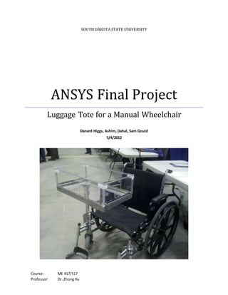
  • 2. Background / Purpose Two of the group members, Danard and Sam, were working on a mechanical engineering senior design project requiring some finite element analysis. The goal of the senior design project was to design a luggage tote for a manual wheelchair as shown in Figure 1. The tote was designed to hold 30 lbs with a safety factor of 2. The tote frame was constructed entirely out of 6061 T-6 aluminum alloy. The FEA was performed in ANSYS and involved finding the maximum von Mises stress and deflection of the tote under various degrees of loading. The load was applied at the corner of the tote furthest from the mounting pole (a.k.a. the “mast”) to produce the worst-case deflection and internal stress. Figure 1: Luggage Tote for a Manual Wheelchair
  • 3. Deflection To simulate the presence of the wheelchair and its rigidity, we simply created a 2-in boundary condition which fixed the mast in the x, y, and z direction at the bottom of the mast. Lastly, a 30-lb force over 91 nodes was applied in the downward (negative y-axis direction) as shown in Figure 2. Figure 2: Boundary Conditions and Load
  • 4. For our FEA deflection analysis, there was a maximum deflection of 1.63 inches. This maximum deflection occurred mostly at the point where the load was applied which was expected. As the Figure 3 below shows, the deflection is distributed evenly throughout the mast. The most distributed load deflection occurs along the front and left angle bar whilst the least amount occurs on the right and back angle bar. Figure 3: Deflection Only, 30-lb Load
  • 5. The next three figures show the deflection with respect to the initial position of the tote at various view angles. The black lines arranged in a grid represent the tote in its unloaded position and the colored solid part shows the tote when it is loaded. The deflection is again 1.63 inches. Figure 4: Deflection + Initial Position, 30-lb Load, View 1 Figure 5: Deflection + Initial Position, 30-lb Load, View 2
  • 6. The deflection shown in the above three figures (but especially evident in Figure 6) is exaggerated from real life due to differences in the area covered by the applied distributed load. In ANSYS, we were able to apply a load on a smaller area toward the far corner, whereas in an experimental setting the load was distributed more toward the middle of the tote. In order to compare the behavior of the tote in ANSYS to that of the real-life experimental setting, loads were applied from 0 – 60 lbs in 5-lb increments in ANSYS and the deflections were plotted. This was compared to the same set of data collected experimentally. These deflection curves are illustrated in Figure 7. As one can see, both the ANSYS and experimental curves follow a close-to-linear pattern. However, the curve of the experimental deflection has a lesser slope. Once again, the difference here is probably due to how the load was distributed in ANSYS versus how it was able to be distributed in real life. In the experimental setting, the weight was distributed closer to the center of the tote rather than the far edge, which would result in lesser deflection for any given amount of weight. Figure 6: Deflection + Initial Position, 30-lb Load, View 3
  • 7. Figure 7: Deflection Curves Stress The stress that was exerted by the 30-lb load is shown in the figures below at different view angles. The yield stress for the 6061 T-6 aluminum frame was 24 ksi. The most common level of von Mises stress exerted on the tote was about 8.25 ksi, which provided a safety factor of 2.9. This exceeds the desired safety factor 2.0, which is great but may be slightly too high for this application. However, this prevents a careless user of the product from doing harm to the tote. 0 0.5 1 1.5 2 2.5 3 3.5 0 10 20 30 40 50 60 70 Deflection(in) Weight (lb) ANSYS Experimental
  • 8. Figure 8: Von Mises Stresses, View 1 Figure 9: Von Mises Stresses, View 2
  • 9. The maximum stress for this tote was 37.14 ksi, which admittedly exceeds the yield stress. This means that if the tote was to fail, it would fail in this particular area. The area where the maximum stress occurs can be seen in Figure 10 in the small area shown below. However, it is speculated that the maximum stress is actually less than 37.14 ksi and the reason for such a high calculated stress is due to limitations in the finite element grid size. In an experimental setting, the deformation of the tote frame is completely elastic even with twice the load experienced in ANSYS—that is, 60 lbs. Figure 10: Location of Maximum Stress