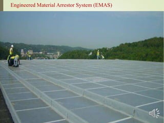
1
1
2
Guided by, Presented by,
Ms. SARITHA JASWANT CHINNU MOHANAN
Asst. Professor Reg No: 11134435
Civil Department S7 Civil
KVM CE & IT KVM CE & IT
CONTENTS3
 INTRODUCTION
 MATERIAL REQUIREMENTS
 MATERIAL COMPOSITION OF ARRESTOR BED
 DESIGN CONSIDERATIONS
 ARRESTOR BED GEOMETRY
 THEORY OF OPERATION
 EMAS INSTALLATIONS
 SUCCESS RECORDS
 CASE STUDIES
 ADVANTAGES AND DISADVANTAGES
 CONCLUSIONS
 REFERENCE
4
Aircraft overruns are a frequent occurrence during
landing & takeoff.
It is reported to be the 4th largest cause of airline
fatalities.
Overrun :
• Occurs when aircraft passes beyond the end of
runway during aborted takeoff or while landing
• Responsible for 97% runway accidents
• 30% of all aircraft accidents
To minimize the hazards of overruns, FAA put
forward the concept of a safety area beyond the
runway end into airport design standards.
5
Continued…
 But construction of RESA becomes impracticable in
airports where there is no area available due to natural
obstacles.
 EMAS is a crushable concrete that is placed at the end of
runways in order to stop the failed takeoff or landing of a
fully loaded airliner.
 The EMAS bed is composed of blocks of foamed cement
concrete that are joined and sealed on top.
 EMAS has an outstanding success record on all incidents
occurred in past years.
Continued…
1
6
7
Engineered Material Arrestor System (EMAS)
8
MATERIAL REQUIREMENTS
Water-resistant.
Not attract birds, wildlife or other creatures.
Constant strength and density characteristics.
Resistant to deterioration. (Salts, aircraft fuels, water and UV rays.)
Non sparking and non combustable.
Should not promote any plant growth.
Non flammable.
MATERIAL COMPOSITION
Component Quantity
Cement type II A-LL 42,5 R [kg] 05
Limestone filler [kg] 10
Expanded polystyrene [L] 42
Water [L] 07.90
Air entraining agent [g] 81.75
w∕c ratio 01.58
9
Recommended by the FAA advisory circular (FAA 2005)
DESIGN REQUIREMENTS
Based on:
 Weight of the biggest aircraft served by the airport.
 Aircraft parameters like type, landing gear configuration and
tyre pressure.
 Available runway safety-area space.
10
1. Concept 4. Drainage
2. Location 5. Width
3. Design 6. Base
Concept:
Designed to stop overrunning aircrafts by exerting
predictable deceleration forces on its landing gear as the
EMAS materials deforms.
Must be designed for 20 year service life.
Location:
Located beyond the end of the runway and centered on the
extended runway centerline.
Usually begin at some setback distance from the end of the
runway to avoid damage due to jet blast and undershoots.1
11
Design:
EMAS performance is dependent not only on aircraft
weight, but also on landing gear configuration and tyre
pressure.
Design method must be derived from field or lab tests.
Testing may be based either on passage of an actual
aircraft or an equivalent single wheel load through a test
bed.
Drainage:
The EMAS must be designed to prevent water from
accumulating on the surface of the EMAS bed, the runway
or the runway safety area.1
12
ARRESTOR-BED GEOMETRY
 The arrestor system is constructed above paved material.
 The arrestor bed begins with a 229mm thickness.
 The bed is sloped to attain a 610mm thickness over a 42.7m
length.
13
 A constant thickness of 610 mm for 42.7m.
 Bed sloped from 610mm to 762mm over a 7m length.
 762mm thickness for remaining portion of the arrestor-bed
length.
Arrester bed geometry
14
15
THEORY OF OPERATION
As an aircraft enters the bed, wheel crushes the
EMAS material creating a wheel-tire interface.
This interface provides resistive loads to decelerate
the aircraft.
Drag forces are induced on the landing gear.
 As the aircraft transition from the rigid pavement
lead to the arrestor bed, landing gear strut
experiences a vertical force drop at the arrestor bed
start.
16
Landing gear- Arrestor bed interaction.
17
1
18
Continued…
The 610mm arrestor-bed section for lighter
weight aircraft.
The 762mm arrestor-bed section for heavier
aircraft.
Maximum drag force developed at 762-mm
arrestor-bed section.
19
Landing gear crushed the EMAS
1
20
21
EMAS INSTALLATIONS
o Installations constructed only by FAA approved
supplier- ESCO.
o Suited for airports that don’t have adequate space to
meet the required dimensions set forth by FAA.
o 1st in JFK,1996.
o 74 EMAS installed since 1996. (47 U.S. airports)
o 15 EMAS installations remain to be completed during
2015-2016.
o Average of 4 installations yearly occurs in U.S.
o After an EMAS arrestment, only the damaged blocks
need to be replaced.
1
22
INSTALLATIONS OUTSIDE U.S
In China, Spain, Taiwan
 Jiuzhai Huanglong Airport, Sichuan Province,
China
 Madrid-Barajas International Airport, Madrid,
Spain
 Songshan Airport, Taipei City, Taiwan
1
23
ESCO Projects currently under contract
N0:
Boston Logan International
Airport, Boston, USA24
25
1
26
SUCCESS RECORDS27
80 EMAS installed around the world.
Majority in US. (about 74 in 47 airports)
9 aircrafts arrested.
More than 240 people have been protected
from serious injury only due to EMAS.
No negative result is reported yet.
1. John F-Kennedy Airport incident may-30,2003
28
CASE STUDIES
McDonnell Douglas MD-11F ,operated by Gemini
Air Cargo.
Due to a late touchdown in normal night visibility , a
runway overrun was resulted.
Only minor damage occurred to the air craft.
All the occupants were uninjured.
29 1. John F-Kennedy Airport incident
May-30, 2003
2. Charleston (CRW) Airport Arrestment
30
Bombardier CRJ 200 , operated by PSA
Airlines
High speed rejected take off in normal day
visibility.
None of the 34 occupants were injured.
31
2. Charleston Airport Arrestment,
19 Jan. 2010
32
3. Teterboro Airport incident on October 1 , 2010
Gulfstream G-IV , operated by Jennifer
Friedberg (General Aviation Flying Service)
Due to a deep landing in normal day
visibility, aircraft overran the end of the
runway at a high speed.
None of the occupants were injured.
33
3. Teterboro Airport incident on Oct 1, 2010
1
34
ADVANTAGES
The EMAS material is non-threatening to
Aircraft engines
Avoid foreign-object damage (FOD)
Non-combustible
Highly energy absorbent
Has predictable load-deflection behaviour
Avoids over cost
Avoids environmental issues
Enhance airport and aircraft safety
35
DISADVANTAGES
The main disadvantage of the EMAS is its
less durability.
Has only 20 year service life with a
maintenance after every 10 year.
36
DEVELOPMENTS IN EMAS
Lot of researches are carried out in account of the
improvement, cost reduction, durability..
“EMASMAX” is the third generation upgrade of
the EMAS .
37
38
EMASMAX arrestor beds are composed of blocks of
light weight, crushable cellular cement material.
Easy and quick to install.
Improved durability and less cost.
Maximizes the runway safety.
EMASMAX
CONCLUSIONS
 The issues of risk of safety related to the available RESA in
airports can be solved by EMAS.
 Ideal solution for the aircraft overrun problem is the FAA
approved Engineered Material Arresting System (EMAS).
 EMAS is highly economic while considering the life cost and
aircraft cost.
 Research should be conducted to improve the service life of
EMAS.
 EMAS should be installed in more airports to avoid the overrun
and RESA issues.
39
REFERENCE
 Wail N. Al-Rifaie , Nabeel I. Al-Sarraj, Salama G. Sulaiman,
‘‘Development of an Engineered Material Arresting System to
Protect Overrun Aircraft” , September 4, 2014.
 Matthew A. Barsotti, John Mark Howard Puryear, David J.
Stevens ,“Developing Improved Civil Aircraft Arresting
Systems” , ACRP report 29, 2013.
 Ernest Heymsfield, W. Micah Hale, Tyler L. Halsey, “Aircraft
Response in an Airfield Arrestor System during an Overrun”
ASCE library, 15 March 2012.
 E. Heymsfield, W. M. Hale and T. L. Halsey, “Optimizing Low
Density Concrete Behaviour for Soft Ground Arrestor
Systems”, 2012.
40
1
41 Continued..
 Chun- shui JIANG, Hong- yu YAO, Xian- bo
XIAO1, Xiang- jun KONG, Ya- jie SHI ,
“Phenomena of Foamed Concrete under Rolling of
Aircraft Wheels”, Science Tech 2014.
 Marco Bassani, Emanuele Sacchi and Fulvio
Canonico, “ Performance Prediction for Innovative
Crushable Material Used in Aircraft ArrestorBeds” ,
2011.
 Ernest Heymsfield, “Sensitivity Analysis of
Engineered Material Arrestor Systems to Aircraft
and Arrestor Material Characteristics”, 2014.
42
43
THANK U

EMAS - Engineered Material Arrestor System

  • 1.
  • 2.
    1 2 Guided by, Presentedby, Ms. SARITHA JASWANT CHINNU MOHANAN Asst. Professor Reg No: 11134435 Civil Department S7 Civil KVM CE & IT KVM CE & IT
  • 3.
    CONTENTS3  INTRODUCTION  MATERIALREQUIREMENTS  MATERIAL COMPOSITION OF ARRESTOR BED  DESIGN CONSIDERATIONS  ARRESTOR BED GEOMETRY  THEORY OF OPERATION  EMAS INSTALLATIONS  SUCCESS RECORDS  CASE STUDIES  ADVANTAGES AND DISADVANTAGES  CONCLUSIONS  REFERENCE
  • 4.
    4 Aircraft overruns area frequent occurrence during landing & takeoff. It is reported to be the 4th largest cause of airline fatalities. Overrun : • Occurs when aircraft passes beyond the end of runway during aborted takeoff or while landing • Responsible for 97% runway accidents • 30% of all aircraft accidents To minimize the hazards of overruns, FAA put forward the concept of a safety area beyond the runway end into airport design standards.
  • 5.
    5 Continued…  But constructionof RESA becomes impracticable in airports where there is no area available due to natural obstacles.  EMAS is a crushable concrete that is placed at the end of runways in order to stop the failed takeoff or landing of a fully loaded airliner.  The EMAS bed is composed of blocks of foamed cement concrete that are joined and sealed on top.  EMAS has an outstanding success record on all incidents occurred in past years.
  • 6.
  • 7.
  • 8.
    8 MATERIAL REQUIREMENTS Water-resistant. Not attractbirds, wildlife or other creatures. Constant strength and density characteristics. Resistant to deterioration. (Salts, aircraft fuels, water and UV rays.) Non sparking and non combustable. Should not promote any plant growth. Non flammable.
  • 9.
    MATERIAL COMPOSITION Component Quantity Cementtype II A-LL 42,5 R [kg] 05 Limestone filler [kg] 10 Expanded polystyrene [L] 42 Water [L] 07.90 Air entraining agent [g] 81.75 w∕c ratio 01.58 9 Recommended by the FAA advisory circular (FAA 2005)
  • 10.
    DESIGN REQUIREMENTS Based on: Weight of the biggest aircraft served by the airport.  Aircraft parameters like type, landing gear configuration and tyre pressure.  Available runway safety-area space. 10 1. Concept 4. Drainage 2. Location 5. Width 3. Design 6. Base
  • 11.
    Concept: Designed to stopoverrunning aircrafts by exerting predictable deceleration forces on its landing gear as the EMAS materials deforms. Must be designed for 20 year service life. Location: Located beyond the end of the runway and centered on the extended runway centerline. Usually begin at some setback distance from the end of the runway to avoid damage due to jet blast and undershoots.1 11
  • 12.
    Design: EMAS performance isdependent not only on aircraft weight, but also on landing gear configuration and tyre pressure. Design method must be derived from field or lab tests. Testing may be based either on passage of an actual aircraft or an equivalent single wheel load through a test bed. Drainage: The EMAS must be designed to prevent water from accumulating on the surface of the EMAS bed, the runway or the runway safety area.1 12
  • 13.
    ARRESTOR-BED GEOMETRY  Thearrestor system is constructed above paved material.  The arrestor bed begins with a 229mm thickness.  The bed is sloped to attain a 610mm thickness over a 42.7m length. 13  A constant thickness of 610 mm for 42.7m.  Bed sloped from 610mm to 762mm over a 7m length.  762mm thickness for remaining portion of the arrestor-bed length.
  • 14.
  • 15.
  • 16.
    THEORY OF OPERATION Asan aircraft enters the bed, wheel crushes the EMAS material creating a wheel-tire interface. This interface provides resistive loads to decelerate the aircraft. Drag forces are induced on the landing gear.  As the aircraft transition from the rigid pavement lead to the arrestor bed, landing gear strut experiences a vertical force drop at the arrestor bed start. 16
  • 17.
    Landing gear- Arrestorbed interaction. 17
  • 18.
  • 19.
    Continued… The 610mm arrestor-bedsection for lighter weight aircraft. The 762mm arrestor-bed section for heavier aircraft. Maximum drag force developed at 762-mm arrestor-bed section. 19
  • 20.
    Landing gear crushedthe EMAS 1 20
  • 21.
    21 EMAS INSTALLATIONS o Installationsconstructed only by FAA approved supplier- ESCO. o Suited for airports that don’t have adequate space to meet the required dimensions set forth by FAA. o 1st in JFK,1996. o 74 EMAS installed since 1996. (47 U.S. airports) o 15 EMAS installations remain to be completed during 2015-2016. o Average of 4 installations yearly occurs in U.S. o After an EMAS arrestment, only the damaged blocks need to be replaced.
  • 22.
    1 22 INSTALLATIONS OUTSIDE U.S InChina, Spain, Taiwan  Jiuzhai Huanglong Airport, Sichuan Province, China  Madrid-Barajas International Airport, Madrid, Spain  Songshan Airport, Taipei City, Taiwan
  • 23.
    1 23 ESCO Projects currentlyunder contract N0:
  • 24.
  • 25.
  • 26.
  • 27.
    SUCCESS RECORDS27 80 EMASinstalled around the world. Majority in US. (about 74 in 47 airports) 9 aircrafts arrested. More than 240 people have been protected from serious injury only due to EMAS. No negative result is reported yet.
  • 28.
    1. John F-KennedyAirport incident may-30,2003 28 CASE STUDIES
  • 29.
    McDonnell Douglas MD-11F,operated by Gemini Air Cargo. Due to a late touchdown in normal night visibility , a runway overrun was resulted. Only minor damage occurred to the air craft. All the occupants were uninjured. 29 1. John F-Kennedy Airport incident May-30, 2003
  • 30.
    2. Charleston (CRW)Airport Arrestment 30
  • 31.
    Bombardier CRJ 200, operated by PSA Airlines High speed rejected take off in normal day visibility. None of the 34 occupants were injured. 31 2. Charleston Airport Arrestment, 19 Jan. 2010
  • 32.
    32 3. Teterboro Airportincident on October 1 , 2010
  • 33.
    Gulfstream G-IV ,operated by Jennifer Friedberg (General Aviation Flying Service) Due to a deep landing in normal day visibility, aircraft overran the end of the runway at a high speed. None of the occupants were injured. 33 3. Teterboro Airport incident on Oct 1, 2010
  • 34.
  • 35.
    ADVANTAGES The EMAS materialis non-threatening to Aircraft engines Avoid foreign-object damage (FOD) Non-combustible Highly energy absorbent Has predictable load-deflection behaviour Avoids over cost Avoids environmental issues Enhance airport and aircraft safety 35
  • 36.
    DISADVANTAGES The main disadvantageof the EMAS is its less durability. Has only 20 year service life with a maintenance after every 10 year. 36
  • 37.
    DEVELOPMENTS IN EMAS Lotof researches are carried out in account of the improvement, cost reduction, durability.. “EMASMAX” is the third generation upgrade of the EMAS . 37
  • 38.
    38 EMASMAX arrestor bedsare composed of blocks of light weight, crushable cellular cement material. Easy and quick to install. Improved durability and less cost. Maximizes the runway safety. EMASMAX
  • 39.
    CONCLUSIONS  The issuesof risk of safety related to the available RESA in airports can be solved by EMAS.  Ideal solution for the aircraft overrun problem is the FAA approved Engineered Material Arresting System (EMAS).  EMAS is highly economic while considering the life cost and aircraft cost.  Research should be conducted to improve the service life of EMAS.  EMAS should be installed in more airports to avoid the overrun and RESA issues. 39
  • 40.
    REFERENCE  Wail N.Al-Rifaie , Nabeel I. Al-Sarraj, Salama G. Sulaiman, ‘‘Development of an Engineered Material Arresting System to Protect Overrun Aircraft” , September 4, 2014.  Matthew A. Barsotti, John Mark Howard Puryear, David J. Stevens ,“Developing Improved Civil Aircraft Arresting Systems” , ACRP report 29, 2013.  Ernest Heymsfield, W. Micah Hale, Tyler L. Halsey, “Aircraft Response in an Airfield Arrestor System during an Overrun” ASCE library, 15 March 2012.  E. Heymsfield, W. M. Hale and T. L. Halsey, “Optimizing Low Density Concrete Behaviour for Soft Ground Arrestor Systems”, 2012. 40
  • 41.
    1 41 Continued..  Chun-shui JIANG, Hong- yu YAO, Xian- bo XIAO1, Xiang- jun KONG, Ya- jie SHI , “Phenomena of Foamed Concrete under Rolling of Aircraft Wheels”, Science Tech 2014.  Marco Bassani, Emanuele Sacchi and Fulvio Canonico, “ Performance Prediction for Innovative Crushable Material Used in Aircraft ArrestorBeds” , 2011.  Ernest Heymsfield, “Sensitivity Analysis of Engineered Material Arrestor Systems to Aircraft and Arrestor Material Characteristics”, 2014.
  • 42.
  • 43.