Computer Aided Analysis and Design of Multi-Storeyed Building using Staad Pro
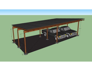
3 d model v1
1.
2. Page 1 of 1
Job #A1002 3/5/2013 MP1
Wind Load Calculations for Flush Mounted Solar
Photovoltaic Array
Analysis compliant with on ICC-AC 428, ASCE 7-05, and IBC 2009
Analysis Method: Method 2, Components and Cladding
Project Specific Values:
Exposure Category B
Residential (Category II)
Gable/Hip
3 Roof zone
10.7 sq ft Area tributary to the footing
24 ft Least Horizontal dimension of roof
18° Roof slope
85 mph 3 second gust speed
15 ft Mean height of array above ground
Calculations:
1 I Importance Factor (ASCE 7-05 Fig 6-11 to Table 6-1)
3 a Roof Zone Width (ASCE 7-05 Fig 6-11 to Table 6-1)
0.7 K_z Velocity Pressure Exposure Coefficient (ASCE 7-05 Table 6-3)
1 K_zt Gust Effect Factor (ASCE 7-05 Section 6.5.8.1)
0.85 K_d Wind Directionality Factor (ASCE 7-05 Table 6-4)
-2.58 GC_pNeg External Pressure Coefficient - Uplift (ASCE 7-05 Fig 6-11 to Fig 6-16)
0.49 GC_pPos External Pressure Coefficient - Downforce (ASCE 7-05 Fig 6-11 to Fig 6-16)
0 GC_pi Internal Pressure Coefficient (ICC AC-428 Section 3.1.3.1.1)
11.01 q_h 0.00256 * K_z * K_zt * K_d * V^2 * I (ASCE 7-05 EQ 6-15)
-28.36 P_up P = q_h * (GC_pNeg) <= 10 psf (Per ICC AC-428 Section 3.1.3.1.1)
5.42 P_down P = q_h * (GC_pPos) (Per ICC AC-428 Section 3.1.3.1.1)
Results:
-302.4 LB Uplift Force Acting on Footing
57.8 LB Downward Force Acting on Footing
• PV System is parallel to mounting plane
• Array has a 2 - 10 in. gap between system and MP
• System is not within 10 inches of a roof edge or ridge
• Minimum 0.25 in. gap between adjacent panels
• Not for use in hurricane regions
• Pressure is applied normal to the module surface
• System is no more than 60 ft above the ground
• Roof Angle is less than or equal to 45 degrees