Training2 ppt
•Download as PPT, PDF•
2 likes•508 views

Presentation based on PCB Designing and 8051 Microcontrollers..

Recommended
More Related Content
What's hot
What's hot (20)
Viewers also liked
Viewers also liked (20)
Similar to Training2 ppt
Similar to Training2 ppt (20)
Recently uploaded
Recently uploaded (20)
Training2 ppt
- 2. Overview What is a PCB? Why use a PCB? How do I make a PCB? 2
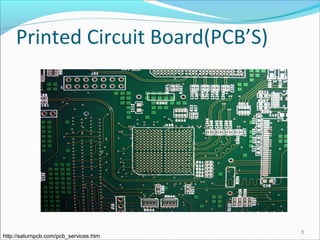
- 3. Printed Circuit Board Circuit connects components through board Made of alternating layers of conducting and insulating materials 3 http://www.seilpcb.co.kr/products/images/2_1_img5.gif
- 4. Why PCB? • Features • Surprisingly Affordable • Highly reliable • Compact • Drawbacks • Requires more layout than other board types • Higher initial cost than wire wrap or point-to-point construction 4 http://en.wikipedia.org/wiki/File:Breadboard_complex.jpg
- 5. PCB Design Steps 1 Design the circuit 2 Place the components 3 Route the wires 4 Manufacture 5
- 6. EDA Software • PCB design software package • Design the circuit (Schematics editor) • Place the components (PCB editor) • Route the wires (Autorouter module) • Examples: • Express Schematics • ExpressPCB • Proteus(ISIS) 6
- 7. Schematic Capture Pin in/outs Components Interconnections Easily Readable High-Level Block Diagram 7 All pictures of schematics and EAGLE screenshots from http://www.sparkfun.com/tutorials/108 and http://www.sparkfun.com/tutorials/109
- 8. Placement of Components • Rat’s Nest 8
- 9. Placement of Components • Place big components first- e.g. microcontroller • Place components in separate functional groups • Put a ground plane under all components 9
- 10. Signal Routing Component Placement Surface mount • Top and bottom planes • Minimal routing area Through-hole mounted • All components on same side • Reduces routing area on all planes 10http://www.ehow.com/how_8306661_solder-mini-components.html http://blog.amal.net/?p=188
- 11. Signal Routing Traces are wires connecting components Traces can be routed through multiple layers 11
- 12. Vias and Pads Vias are connections between layers Pads are copper areas for pin connections 12
- 15. THE 8051 MICROCONTROLLER PIN DIAGRAM IT’S COMPONENTS IT’S ADVANTAGES DISADVANTAGES COMPARISON WITH DIFFERENT MEMBERS 15
- 16. 8051 Basic Component 4K bytes internal ROM 128 bytes internal RAM Four 8-bit I/O ports (P0 - P3). Two 16-bit timers/counters One serial interface 64k external memory for code 64k external memory for data 210 bit addressable Microcontroller
- 18. IMPORTANT PINS (IO Ports)IMPORTANT PINS (IO Ports) Port 2Port 2 (( pins 21-28pins 21-28 (( P2.0P2.0 ~~ P2.7P2.7 )) 8-bit R/W - General8-bit R/W - General Purpose I/OPurpose I/O OrOr highhigh byte of thebyte of the addressaddress bus forbus for external memoryexternal memory designdesign
- 19. IMPORTANT PINS (IO Ports)IMPORTANT PINS (IO Ports) Port 3Port 3 (( pins 10-17pins 10-17 (( P3.0P3.0 ~~ P3.7P3.7 )) General Purpose I/OGeneral Purpose I/O if not using any of theif not using any of the internal peripheralsinternal peripherals (timers) or external(timers) or external interrupts.interrupts.
- 20. Register sA B R0 R1 R3 R4 R2 R5 R7 R6 DPH DPL PC DPTR PC Some 8051 16-bit Register Some 8-bitt Registers of the 8051
- 21. Data memory XM DM MOV A,62H MOV R1,#62H MOV A@R1 MOV A,0A2H MOV R1,#0A2H MOV A@R1
- 22. Comparison some of the 8051 Family Members ROM RAM Timer 8051 4k 128 2 8031 - 128 2 8751 4k eprom 128 2 8052 8krom 256 3 8032 - 256 3 8752 8k eprom 256 3
- 23. Comparison of the 8051 Family Members ROM type 8031 no ROM 80xx mask ROM 87xx EPROM 89xx Flash EEPROM 89xx 8951 8952 8953 8955 898252 891051 892051 Example (AT89C51,AT89LV51) AT= ATMEL(Manufacture) C = CMOS technology LV= Low Power(3.0v)
- 24. Advantages of Microcontroller based System As the peripherals are integrated into a single chip, the overall system cost is very less The product is of small size compared to micro processor based system The system design now requires very little efforts As the peripherals are integrated with a microprocessor the system is more reliable Though microcontroller may have on chip ROM,RAM and I/O ports, addition ROM, RAM I/O ports may be interfaced externally if required On chip ROM provide a software security SJCET
- 25. Disadvantages of microprocessor The overall system cost is high A large sized PCB is required for assembling all the components Overall product design requires more time Physical size of the product is big A discrete components are used, the system is not reliable SJCET
Editor's Notes
- Electronic Design Automation
- Error wire