Controlling Post-Completion Flow in Steam-Assisted Gravity Drainage Wells
•
0 likes•1,041 views

Shaelyn Gordon, Adriana Hightower, SPE Nadine Macklin, Baker Hughes Copyright 2014, Society of Petroleum Engineers. Reprinted from the Journal of Petroleum Technology with permission.

Recommended
More Related Content
What's hot
What's hot (20)
Similar to Controlling Post-Completion Flow in Steam-Assisted Gravity Drainage Wells
Similar to Controlling Post-Completion Flow in Steam-Assisted Gravity Drainage Wells (20)
More from Baker Hughes
More from Baker Hughes (10)
Recently uploaded
Recently uploaded (20)
Controlling Post-Completion Flow in Steam-Assisted Gravity Drainage Wells
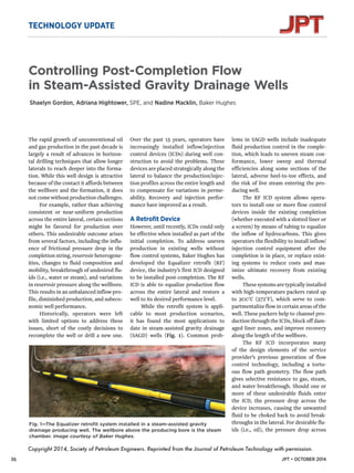
- 1. TECHNOLOGY UPDATE Controlling Post-Completion Flow in Steam-Assisted Gravity Drainage Wells Shaelyn Gordon, Adriana Hightower, SPE, and Nadine Macklin, Baker Hughes The rapid growth of unconventional oil and gas production in the past decade is largely a result of advances in horizon-tal drilling techniques that allow longer laterals to reach deeper into the forma-tion. While this well design is attractive because of the contact it affords between the wellbore and the formation, it does not come without production challenges. For example, rather than achieving consistent or near-uniform production across the entire lateral, certain sections might be favored for production over others. This undesirable outcome arises from several factors, including the influ-ence of frictional pressure drop in the completion string, reservoir heterogene-ities, changes to fluid composition and mobility, breakthrough of undesired flu-ids (i.e., water or steam), and variations in reservoir pressure along the wellbore. This results in an unbalanced inflow pro-file, diminished production, and subeco-nomic well performance. Historically, operators were left with limited options to address these issues, short of the costly decisions to recomplete the well or drill a new one. Over the past 15 years, operators have increasingly installed inflow/injection control devices (ICDs) during well con-struction to avoid the problems. These devices are placed strategically along the lateral to balance the production/injec-tion profiles across the entire length and to compensate for variations in perme-ability. Recovery and injection perfor-mance have improved as a result. A Retrofit Device However, until recently, ICDs could only be effective when installed as part of the initial completion. To address uneven production in existing wells without flow control systems, Baker Hughes has developed the Equalizer retrofit (RF) device, the industry’s first ICD designed to be installed post-completion. The RF ICD is able to equalize production flow across the entire lateral and restore a well to its desired performance level. While the retrofit system is appli-cable to most production scenarios, it has found the most applications to date in steam-assisted gravity drainage (SAGD) wells (Fig. 1). Common prob-lems in SAGD wells include inadequate fluid production control in the comple-tion, which leads to uneven steam con-formance, lower sweep and thermal efficiencies along some sections of the lateral, adverse heel-to-toe effects, and the risk of live steam entering the pro-ducing well. The RF ICD system allows opera-tors to install one or more flow control devices inside the existing completion (whether executed with a slotted liner or a screen) by means of tubing to equalize the inflow of hydrocarbons. This gives operators the flexibility to install inflow/ injection control equipment after the completion is in place, or replace exist-ing systems to reduce costs and max-imize ultimate recovery from existing wells. These systems are typically installed with high-temperature packers rated up to 300°C (572°F), which serve to com-partmentalize flow in certain areas of the well. These packers help to channel pro-duction through the ICDs, block off dam-aged liner zones, and improve recovery along the length of the wellbore. The RF ICD incorporates many of the design elements of the service provider’s previous generation of flow control technology, including a tortu-ous flow path geometry. The flow path gives selective resistance to gas, steam, and water breakthrough. Should one or more of these undesirable fluids enter the ICD, the pressure drop across the device increases, causing the unwanted fluid to be choked back to avoid break-throughs in the lateral. For desirable flu-ids Fig. 1—The Equalizer retrofit system installed in a steam-assisted gravity drainage producing well. The wellbore above the producing bore is the steam chamber. Image courtesy of Baker Hughes. Copyright 2014, Society of Petroleum Engineers. Reprinted from the Journal of Petroleum Technology with permission. (i.e., oil), the pressure drop across 36 JPT • OCTOBER 2014
- 2. the device decreases, thus allowing selective production. All of this is achieved autonomous-ly by the device, without intervention on behalf of the operator to scale back unwanted fluids or promote hydrocar-bon flow. The system can control flow under a wide range of changing res-ervoir conditions throughout the well’s life, thus maximizing oil recovery from the well while reducing the steam/oil ratio (SOR) for improved sweep efficien-cy. Before installation, the devices can be set to one of the multiple field-adjustable flow resistance ratings to further opti-mize performance on a reservoir basis. The device’s antiplugging and self-cleaning design enables reliable, long-term operation without inter-vention. A large inflow area allows for low fluid velocities and mini-mizes erosional effects to further enhance reliability. Alberta Case Study An operator in the Alberta, Canada, oil sands was experiencing poor confor-mance in the steam chamber along the length of a producing SAGD well, which resulted in localized hot spots in the lateral, a degraded liner, and restricted production. A device to remedy the pro-duction problem would need to generate a uniform steam profile along the lateral to eliminate the hot spots and the liner degradation and would have to fit inside the well’s 8⅝-in. liner. Starting in mid-2013, the service provider and operator worked togeth-er to devise an appropriate deployment strategy for the RF ICD, which began with detailed field and reservoir analyses to optimize the completion design. Inte-gral to this work was the detailed study of the formation geology surrounding the well. Even minor changes to geol-ogy along the lateral can have a signifi-cant effect on the performance of the ICD. Understanding these changes and accounting for them in the design and placement of each ICD system helps to optimize the productivity of the lateral. The work resulted in the opti-mal sizing and placement of tubing-deployed 800 Oil (B/D) Oil Rate vs. Time Equalizer RF ICD Installation 0 100 200 300 400 500 600 700 Time (days) 700 600 500 400 300 200 100 0 Fig. 2—Within a month of installation, the retrofit (RF) inflow/injection control device (ICD) sharply increased oil production and reduced the steam/oil ratio in this steam-assisted gravity drainage well. Graph courtesy of Baker Hughes. ICDs and swell packers to compartmentalize the flow in the well’s lateral section. The completion was designed around temperature, pres-sure, and geological and well-proximi-ty data. And the design was optimized to counteract the specific production-limiting issues in the producing well to improve wellbore conformance and production efficiency. The planning resulted in a smooth installation of the ICD system and pack-ers, with no unplanned downtime or deployment delays. Within a month of installation, the well recorded an 87% rise in oil production, from 371 B/D to an average of 695 B/D (Fig. 2). The SOR dropped from 4.1% to 2.8%, a decrease of 31%. The operator reported that the installation of the retrofit system made the injector/producer well pair the most prolific in the field. After a month of consistent, im-proved production that almost doubled fluid production rates, the customer installed two additional RF ICD systems across the field and plans to install more. In all, nine retrofit systems have been installed in the same number of wells since September 2013 for various SAGD production operators in Alberta. The operators have experienced similar benefits of improved volumetric sweep and better steam chamber control in their wells. On average, the cumulative oil recovery has increased by more than 25% based on available public data with a 3-month time lag. More Application Options The service provider is now investigat-ing other deployment options for the RF ICD in other wells and with addi-tional tools to shorten deployment time and improve performance. For example, in sandstone and other unconsolidated reservoirs, the well may produce sand in sufficient amounts to hinder reliable RF ICD operation. Common sand-related problems include an inability of stand-alone slotted liners or screens in the completion to provide an adequate flow control, and the buildup of sand depos-its that may limit production. The ICD can be combined with one of several screen systems, including wire-wrapped or metal mesh screens, to control sand production while equal-izing flow across the horizontal interval. These systems have demonstrated an ability to equalize the liquid level along the length of the wellbore and auton-omously prevent the effects of steam or water breakthrough. This helps to optimize sweep efficiency and maximize oil recovery. JPT • OCTOBER 2014 37
- 3. TECHNOLOGY UPDATE In consolidated formations, such as carbonates, the RF ICD can be deployed with a multitasking valve, which is incor-porated into the system’s body to tem-porarily block flow while running the ICD. This option eliminates the need for a concentric string when deploying the device and enables hydraulic activation of packers without fluid loss. Once the device is run to the bottom and packers are set, the valve is activat-ed hydraulically to open the completion string to the formation and allow unre-stricted flow to the ICD. This deployment option has been well accepted because it enables a reduction in rig time. Deploy-ments in new wells using the multitask-ing valve with the ICD have shown a 1- to 2-day reduction in rig time compared with concentric string methods. While the results obtained with the RF ICD depend strongly on the geom-etry of each well and the conditions of each reservoir, the successes observed have led operators to plan deploy-ments of the device in several addition-al wells this year. JPT 38 JPT • OCTOBER 2014