
Recommended
More Related Content
What's hot
What's hot (20)
Similar to Solar Photovoltaic.ppt
Similar to Solar Photovoltaic.ppt (20)
More from AnonymousPerson72
Recently uploaded
Recently uploaded (20)
Solar Photovoltaic.ppt
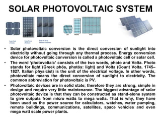
- 1. SOLAR PHOTOVOLTAIC SYSTEM • Solar photovoltaic conversion is the direct conversion of sunlight into electricity without going through any thermal process. Energy conversion device for photovoltaic conversion is called a photovoltaic cell or solar cell. • The word ‘photovoltaic’ consists of the two words, photo and Volta. Photo stands for light (Greek phõs, photós: light) and Volta (Count Volta, 1745– 1827, Italian physicist) is the unit of the electrical voltage. In other words, photovoltaic means the direct conversion of sunlight to electricity. The common abbreviation for photovoltaic is PV. • Photovoltaic devices are in solid state; therefore they are strong, simple in design and require very little maintenance. The biggest advantage of solar photovoltaic device is that they can be constructed as stand-alone system to give outputs from micro watts to mega watts. That is why, they have been used as the power source for calculators, watches, water pumping, remote buildings, communications, satellites, space vehicles and even mega watt scale power plants.
- 2. History of Solar Photovoltaic System • The photovoltaic effect was first observed in electrolytic cells by a French scientist Becquerel in 1839 who found that more current can be generated if more light is allowed to fall in the cell. He also discovered that the increase in current is dependant on the wavelength of light. • Adam and Day first observed the same effect in solids in 1877 while working with selenium. • In 1877, Heinrich Hertz discovered that ultra violet light altered the lowest voltage capable of causing a spark to jump between two metal electrodes. • In 1905, the photovoltaic principle was explained by Albert Einstein. He explained that light behaves like a particle rather than a wave. The energy of each light particle, called photon, depends on its frequency only and is equal to the product of Planck’s constant (h) and frequency of light (f). • An electron in an atom of some materials is able to capture a photon and obtains energy necessary to escape if energy of photon exceeds the binding energy of electron in the atom. Under certain situations, these freed electrons can be made to flow in an external circuit and hence produce electricity. • In 1954, researchers at RCA and Bell Laboratories, USA reported achieving efficiencies of about 6 percent by using devices made of p and n type semiconductors. • Photovoltaic cell most commonly made of silicon, a material called semiconductor, has now been widely used for generating DC electricity.
- 3. Some Information about Solar Cell • Current generation in a solar cell is normally 300 Amperes per square meter area of cell or 30 mA per square centi meter area of cell in a full sunny day • Voltage generation per solar cell is normally from 0.4 – 0.5 Volt • A silicon solar cell of size 10 cm x 10 cm produces a voltage of 0.5 V and power output of 1 watt at a solar radiation intensity of 1000 watt/m2 • Total cost of the photovoltaic system is around Rs. 100 per solar watt • A house normally needs 1000 watts (1 kW) • Cost of installation of the system is Rs. 1.00 lakhs • Life time of a solar system is around 25 years. • The size of a solar cell is normally 10 cm x 10 cm • A commercial solar module contains nearly 36 cells. Each module may have 3 to 5 columns of cells in series in such a way that it supplies the desired output to charge a 12 V battery. • The term ‘Peak Watt’ or Watt Peak’ (wp) is used for power produced by a photovoltaic device around noon on a clear day with beam radiation falling normally on the device and operating at a cell temperature of 25-28 degree Centigrade with solar radiation of 1000 watt/m2. It is the higher output than that usually achieved in the field condition. • The present annual world power production from photovoltaic system is about 10 Mwp while in India about 2 Mwp.
- 4. Applications of Solar Photovoltaic Systems 1. Solar street lighting system 2. Home lighting systems 3. Water pumping systems (for micro irrigation and drinking water supply) 4. Space vehicles and satellites 5. Community radio and television sets 6. Battery charging 7. Weather monitoring 8. Power source for navigational lights 9. Power source for telecommunication equipments 10. Power source for railway signaling equipments.
- 5. The advantages of solar photovoltaic system 1. Absence of moving parts. 2. Direct conversion of light to electricity at room temperature. 3. Can function unattended for long time. 4. Low maintenance cost. 5. No environmental pollution. 6. Very long life. 7. Highly reliable. 8. Solar energy is free and no fuel required. 9. Can be started easily as no starting time is involved. 10. Easy to fabricate. 11. These have high power-to-weight ratio, therefore very useful for space application. 12. Decentralized or dispersed power generation at the point of power consumption can save power transmission and distribution costs. 13. These can be used with or without sun tracking.
- 6. Limitations of solar photovoltaic system • Manufacture of silicon crystals is labour and energy intensive. • Low efficiency. • The insolation is unreliable and therefore storage batteries are needed. • Solar power plants require very large land areas. • Electrical generation cost is very high. • The energy spent in the manufacture of solar cells is very high. • High initial cost
- 7. Insulator, Semi conductor and Conductor • On the basis of band energy (the difference in energy of an electron in the valence band and conduction band), the materials can be classified as insulator, semi- conductor and conductor. • In the energy band model, electrons fill the bands one after another starting with the first, lowest energy band. • The highest fully occupied band is called the valence band (VB). The next highest band, which can be partially occupied or totally empty, is called the conduction band (CB). • The space between the valence band and conduction band contains forbidden energy states and is therefore called the forbidden band (FB). The energy gap between the bands is called the band gap Eg. CONTD.
- 9. • Electrons in the outermost band of an atom determine how an atom will react or join with a neighboring atom, the outermost band is called the valence band. Some electrons in the valence band may be so energetic that they may jump into a still higher band and are so far removed from the nucleus that a small amount of impressed force would cause them to move away from the atom. Such electrons are responsible for the conduction of electricity and this remote band is called a conduction band. • Materials whose valence bands are full have very high band gap (more than 3 eV). Such materials are insulators. Materials on the other hand that have relatively empty valence band and may have some electrons in the conduction band are good conductors. Metals fall in this category. Materials with valence band partly filled have intermediate band gaps (less than 3 eV). Such materials are called semi conductor.
- 11. Why some semiconductors are photo sensitive (The photo effect) • Light, with its photon energy, can provide the energy to lift an electron to a higher orbit. • The photon energy is given by:E = hc/λ where h = Planck’s constant (6.63 x 10⁻³⁴ joule-second); c = speed of light (3 x 10⁸ m/sec). Putting the values and 1 eV = 1.60 x 10⁻¹⁹ Joule; λ = 1.24/Energy of photon; where λ is in microns (10-6 meter) and energy of photon is in eV (electron volt). • If energy of photon is equal to the binding energy or forbidden energy gap (Eg) between valence band and conduction band, the electron after absorption of photon becomes excited and jumps to the conduction band and becomes free electrons for assisting in generating electricity. • λc = 1.24/ Eg; where λc is the critical or cut-off wavelength of light whose energy becomes equal to band energy.If λ> λc ; then the energy of photon is less than Eg for which the electron in the valence band does not get sufficient energy to jump into the conduction band. Hence the above relationship is very important to differentiate the material to be photo sensitive to sunlight based on their forbidden energy gap.
- 12. Why silicon and germanium are photo sensitive to sunlight • The band gap (Eg) for silicon and germanium is 1.1 eV and 0.72 eV respectively. Putting the values in the relationship λc = 1.24/ Eg; λ= 1.12 microns for silicon (which is within the spectral region of sunlight) • λ= 1.72 microns for germanium (which is also within the spectral region of sunlight) • λ= 0.2 microns for carbon having band gap of 6 eV (which is not within the spectral region of sunlight) • For a conductor band gap energy is very very less and Eg≈0. In this case λ > 10 microns which is in the infrared radiation range but not available in the sunlight. • From the analysis, it is clear that only semiconductors like silicon and germanium are sensitive to sunlight but not metal (conductor) or insulator. Some candidate materials for photovoltaic cell in the band gap range of 1 to 2 eV are SiC (band gap of 2.00 eV), CdSe (band gap of 1.74 eV), GaAs (band gap of 1.40 eV) etc.
- 13. Some elements in 3rd, 4th and 5th groups of Periodic Table III rd IVth Vth Boron Carbon (insulator) Nitrogen Aluminum Silicon(Semiconductor) Phosphorus Galium Germanium(Semiconductor) Arsenic Group Elements Indium Tin (Metal) Antimony •Silicon and Germanium are tetravalent i.e., there are four valence electrons in their outermost shell. At about 0 K, both behave as insulator, no free electrons available in the conduction band. At about 300 K (room temperature), some electrons may acquire sufficient thermal energy to break the covalent bond and jump valence band to the conduction band. Some free electrons available in the conduction band for conduction at room temperature. Electronic configuration of Silicon atom
- 14. Intrinsic and Extrinsic semiconductor • A pure semiconductor is called intrinsic semiconductor. Here no free electrons are available since all the covalent bonds are complete and conduction band is empty or unfilled. A pure semiconductor therefore behaves as an insulator. • The semiconductor when added or doped with impurities is called extrinsic semiconductor. The process of adding impurity (extremely in small amounts about 1 part in 108) to a semiconductor to make it extrinsic semiconductor is called Doping. The doped semiconductor attains current conducting properties. If to an intrinsic semiconductor, there is added a small percentage of trivalent or pentavalent atoms, a doped, impure or extrinsic semiconductor is formed.
- 15. Donor atom and N-type semiconductor • If the dopants (like Phosphorus, Arsenic or Antimony) having five valence electrons are added to Si or Ge, they donate one extra electron (negative charge) per atom and therefore referred to as donor atom and semiconductor will become N-type semiconductor.
- 16. Acceptor atom and P-type semiconductor • If the dopants (like Boron, Gallium or Indium) having three valence electrons are added to Si or Ge, only three of the covalent bond can be filled and vacancy that exists in the fourth bond constituting a hole. Such impurities create holes (vacancy of electron or positive charge) which can accept valence electron from the semiconductor and are called acceptor atoms. The semiconductor thus formed is called P-type semiconductor.
- 17. PN JUNCTION • If one side of a single crystal of semiconductor is doped with acceptor impurity atoms and the other side of the same crystal is doped with donor impurity atoms, a PN Junction is formed. The area where the P-type and N-type regions meet is called a PN Junction and the resulting device is a diode. The PN Junction is not produced by simply connecting the P-type and N-type material by welding or other similar process but through sophisticated chemical technique. • In the PN Junction, the donor ion is represented by a plus sign because after this, impurity atom donates an electron, it becomes positive ion. The acceptor ion is indicated by a minus sign because after this, atom accepts an electron from the neighboring atom, it becomes negative ion. Ions are immobile in nature but free charges are mobile in nature. P layer N layer
- 18. Formation of Electric Field in PN Junction
- 20. Flow of Electric Current to Load through External Circuit
- 21. Construction and Working of a Solar Cell
- 22. Array Charge Controller: It is a device to protect the battery from over charging and over discharging. If over charged electrolyte will be lost, internal heating will occur; voltage will rise and reduce battery life. Over discharging also damage the battery.
- 24. Current-Voltage Characteristics of a Solar cell • The behaviour of a solar cell can be characterized by using three parameters i.e., the short circuit current (Isc), the open circuit voltage (Voc) and fill factor. • Open Circuit Voltage: When the external resistance ‘R’ is very high (mega- ohms range or infinity), the condition is called ‘Open Circuit’. Under this condition, there is very less or no current in the circuit. Open circuit current is zero. The open circuit voltage (Voc) of a solar cell is about 0.5 V D.C. • Short Circuit Current: If resistance ‘R’ is reduced gradually and from high value to low value, the terminal voltage of cell falls and current increases. This is similar to a short circuit between positive and negative terminal in which the terminal voltage is zero and current is maximum. This current is called short circuit current (Isc). • Fill Factor (FF): The fill factor is the ratio of maximum power a solar cell can produce (VmIm) to the theoretical limit (Voc Isc) if both voltage and current are simultaneously at the maximum. It indicates how well a junction is made in the cell and how low the series resistance has been made. Solar cell designers strive to increase the ‘FF’ values to minimize internal losses. ‘FF’ for a good silicon cell is about 0.8. • Maximum Efficiency (ηmax): It is the defined as the ratio of maximum electric power output to the incident solar radiation in a solar cell. • Mathematically, ηmax = (VmIm)/ (Is As) • Where Is = Incident solar flux and As = Area of cell.
- 26. Factors affecting the output of a solar cell • Sun light (Irradiance): Solar cell output depends on the level of light or solar radiation flux falling on the solar cell surface. • Temperature of solar cell: Module temperature affects the output voltage inversely. Higher module temperature reduces the voltage by 0.04 to 0.1 volts for every one degree Celsius rise in temperature. Air should be allowed to circulate behind the back of each module so that its temperature does not rise causing the increase of its output.
- 27. Causes for low efficiency of a solar cell • Solar cell does not operate at the theoretical maximum efficiency because of several limitations. The efficiency of a solar cell varies from 12-15 % only. The following factors limit the efficiency of a solar cell and mentioned below. 1. Reflection losses at the top surface of the solar cell. 2. Shading due to charge collection grid at the top surface 3. Incomplete absorption of photon energy due to limited cell thickness 4. Incomplete use of photon energy in excess of forbidden energy 5. Collection losses 6. Voltage factor loss 7. Curve of fill factor loss 8. Series and shunt resistance loss
- 28. Percentage Loss of Efficiency in a Solar Cell Sl.No. Factors responsible for loss of efficiency Percentage of loss 1 No photon absorption (photon energy less than forbidden energy) 23 2 Excess photon energy (photon energy more than forbidden energy) 33 3 Surface reflection 0.5 4 Voltage factor 18 5 Fill factor 5 6 Shading due to charge collection grid 0.05 7 Collection losses 5 8 Series resistance 0.5 TOTAL LOSS 85.05
- 29. Applications of Solar Photovoltaic Conversion • Solar Lantern • Solar Street Light • Solar Fencing • Solar Pumping System
- 30. SOLAR PV SYSTEM DESIGN • EXAMPLE The base condition of operating two CFLs (18 watt each) and two fans (60 watt each) for 6 hours per day is considered which will enable to light two rooms as well as two fans which are enough for a drawing room. A PV system design would require information about what is total load, how many hours one want to run the appliances, which PV module and battery is available for use, what would be the total cost, how much solar radiation is available, etc. A solar PV system design can be done in four steps: Load estimation Estimation of number of PV panels Estimation of battery bank Cost estimation Steps to design a solar PV Step 1: Find out the total energy requirement of the system load (total load). Total load connected to PV panel system = No. of Units X rating of equipment = 2 X 18 + 2 X 60 = 156 watts Total watt-hours rating = Connected load load ( watts) X operating hours = 156 X 6 = 936 watt-hours Step 2 : Find out the number of PV panel required Actual power output of a PV panel = Peak power rating X operating factor = 40 X 0.75 = 30 watt The power available for end use is less (due to lower combined efficiency of the system) = Actual power output of a panel X combined efficiency = 30 X 0.81 =24.3 watts (VA) = 24.3 watts Energy produced by one 40 Wp panel in a day = Actual power output X 8 hours/day (peak equivalent) = 24.3 X 8 = 194.4 watt- hour Number of solar panels required to satisfy given estimated daily load( from Step 1) =Total watt-hour rating (daily load)/ Daily energy produced by a panel = 936/194.4 = 4.81 = 5 (round figure)
- 31. Step 3: Find out the battery requirement Total amp-hour required (total charge to be stored), (battery size should be higher than the actual useful energy due to less combined efficiency of the system) =Total watt – hour rating/(Inverter efficiency X Depth of discharge X Battery voltage) = 936/0.90 X 0.80 X 12 = 108.33 Number of batteries required =Total amp-hour rating/ Battery rating under use = 108.33/120= 0.9 =1 (round figure) Step 4: Find out inverter size Inverter rating (watts or VA) Total connected load to PV panel system=156 watts =156 VA Inverters are available with the rating of 100, 200,500 VA,etc. Therefore, the choice of the inverter should be 200 VA. Cost Estimation of a PV System Cost of arrays = No. of PV modules X Cost/Module = 5 X 2800(for a 40Wp panel @ Rs70/Wp) = Rs 14000 (b) Cost of batteries = No. of Batteries X Cost/Battery = 1 X 7500 = Rs 7500 (c) Cost of Inverter = No. of Inverters X Cost/Inverter = 1 X 5000 = Rs 5000 Total cost of system = A + B + C = 14000 + 7500 + 5000 = Rs 26500 Additional cost of wiring may be taken as 5% of the total system (Rs. 1325/-) Total Cost = Rs. 27,825/-
- 32. Water Pumping Design of a PV system for pumping 25000 litres of water everyday from a depth of about 10 metre is considered. The data required for calculation and the steps of calculation are: Amount of water to be pumped per day= 25000 litre=25 m3 Total vertical lift= 12 metres (5m-elevation,5 m-standing water level, 2m-drawdown) Water density= 1000 kg/m3 Acceleration due to gravity, g= 9.8 m/s2 Solar PV module used= 75 wp Operating factor= 0.75 (PV panel mostly does not operate at peak rated power) Pump efficiency= 30% or 0.30 Mismatch factor= 0.85 Calculations for PV water pumping system Step 1: Determination total daily water requirement Daily water requirement = 25 m3/day Step 2: Determination total dynamic head Total vertical lift= 12 m Frictional losses= 5% of the total vertical lift = 12 X 0.05 = 0.6 metre Total dynamic head (TDH) = 12 + 0.6 =12.6 m Step 3: Determine the hydraulic energy required per day Hydraulic energy required to raise water level = Mass X g X TDH = density X volume X g X DH = (1000 kg/m3) X (25 m3/day) X (9.8 m/s2) X 12.6 = (multiply by 1/3600 to convert second in hours) = 857.5 watt-hour/day
- 33. Step 4: Determine the number of PV panels and pump size Total wattage of PV panel = Total hydraulic energy No. of hours of peak sunshine/day = 857.5/6 = 142.9 watt Considering system losses =Total PV panel wattage/Pump efficiency X Mismatch factor = 142.9/0.3 x 0.85 = 560 watt Considering operating factor for PV panel = Total PV panel wattage after losses/Operating factor = 560/0.75 = 747.3 watt Number of 75 Wp solar PV panels required = 747.3/75 = 9.96 =10 (round figure) Power rating of the motor = 747.3/746 = 1 HP water In this way, a solar PV water pumping system can be designed. The above design has been done assuming the use of a DC motor. A system, can also be designed for an AC motor but one must consider inverter and its efficiency in the calculations. Also, the cost of the solar PV irrigation system can be estimated by considering the individual component cost, e.g. cost of solar panel, cost of motor and cost of pump and wiring cost.
- 34. Numerical-3 Design of a PV system for pumping 25000 litres of water every day from a depth of about 10 metre is considered. The data required for calculation and the steps of calculation are: •Amount of water to be pumped per day= 25000 litre=25 m3 •Total vertical lift= 12 metres (5m-elevation,5 m-standing water level, 2m-drawdown) •Water density= 1000 kg/m3 •Acceleration due to gravity, g= 9.8 m/s2 •Solar PV module used= 75 wp •Operating factor= 0.75 (PV panel mostly does not operate at peak rated power) •Pump efficiency= 30% or 0.30 (can be taken between 0.25 and 0.4). Mismatch factor= 0.85 (PV panel does not operate at maximum powe Calculations for PV water pumping system Step 1: Determination total daily water requirement Daily water requirement = 25 m3/day Step 2: Determination total dynamic head Total vertical lift= 12 m Frictional losses= 5% of the total vertical lift = 12 X 0.05 = 0.6 metre Total dynamic head (TDH) = 12 + 0.6 =12.6 m Step 3: Determine the hydraulic energy required per day Hydraulic energy required to raise water level = Mass X g X TDH = density X volume X g X TDH = (1000 kg/m3) X (25 m3/day) X (9.8 m/s2) X 12.6 m = (multiply by 1/3600 to convert second in hours) = 857.5 watt-hour/day Potential energy of the water is raised due to pumping, which must be supplied to the pump.
- 35. Step 4: Determine solar radiation data Solar radiation data in terms of equivalent peak sunshine radiation (1000 W/m2) varies between about 4 and 7 hours. For exact hours meteorological data should be used. = 6 hours/day (peak of 1000W/m2 equivalent), actual day length is longer (this is equivalent of solar radiation of 180000 watt-hours/month at a given location) Step 5: Determine the number of PV panels and pump size Total wattage of PV panel = (Total hydraulic energy) / (No. of hours of peak sunshine/day) = 857.5/6 = 142.9 watt Considering system losses =Total PV panel wattage/Pump efficiency X Mismatch factor = 142.9/(0.3 x 0.85) = 560 watt Considering operating factor for PV panel = Total PV panel wattage after losses/Operating factor = 560/0.75 = 747.3 watt Number of 75 Wp solar PV panels required = 747.3/75 = 9.96 =10 (round figure) Power rating of the motor = 747.3/746 = 1 HP water In this way, a solar PV water pumping system can be designed. The above design has been done assuming the use of a DC motor. A system can also be designed for an AC motor but one must consider inverter and its efficiency in the calculations. Also, the cost of the solar PV irrigation system can be estimated by considering the individual component cost, e.g. cost of solar panel, cost of motor and cost of pump and wiring cost.
- 36. Numerical-4 Calculate the no module (each module of 40 W output) required for supplying power to operate a pump 60% efficiency if 60 m3 of water to be lifted at a height of 5 m in a period of 4 hours. time vgh W hour hour m s m m m Kg 16 . 204 sec/ 3600 4 5 / 8 . 9 60 / 1000 2 3 3 W W 360 340 6 . 0 16 . 204 9 40 360 Solution: The potential energy is to be given to a mass of water (work) W=PE = mgh Mass = Density x Volume, so W =ρvgh Power = = Pump efficiency = 60% Power = Modules
- 37. Solar Lantern Applications and uses Emergency and/or house lighting, table lamp, camping, patrolling (streets, farms), Hawker / Vendor Stalls, non-electrified remote places: Adult education, mass communication. Easy and convenient alternative to kerosene / petromax / gas. Benefits It is easy to install, no electrical connection is required and no electricity charges. Lantern is made of three main components - the solar PV panel, the storage battery and the lamp. The lamp, battery and electronics all placed in a suitable housing made of metal, plastic or fiber glass. A single charge can operate the lamp for about 4-5 hours. The lantern is basically a portable lighting device suitable for either indoor or outdoor lighting,
- 38. Solar Street Lighting System 1. SPV Module 2. Battery Box 3. Lamp with charge controller 4. Lamp Post The solar street light system comprise of a) 74 Wp Solar PV Module b) 12 V, 75 Ah Tubular plate battery with battery box c) Charge Controller cum inverter (20-35 kHz) d) 11 Watt CFL Lamp with fixtures e) 4 metre mild steel lamp post above ground level with weather proof paint and mounting hardware.
- 39. Solar Fencing • The electric fencing system works by taking power from solar energy. There is a battery bank provided due to which the system runs uninterruptedly during nights and cloudy days. High Security Fence Security Fence Animal Fence Agriculture Fence The impulse carries 10 mA of current and delivers a shock lasting for a fraction of a second. The batteries can be recharged using readymade solar fence chargers. Battery operated solar fences may cost from INR45,000-50,000 per acre (4000 m2). Cheaper versions costing as low as INR10,000-25,000 per acre have been developed using locally made materials in some places in India. •It gives a short, sharp but safe shock to the intruder. •High voltage and very low current generation and Perimeter protection
- 41. The basic building blocks of solar fence • Energizer 2. Earthing (Grounding System) and 3. Fence system Features of solar fencing system a) Easy Construction. b) Power fence can be erected to target species only. c) Low maintenance. d) Long lasting because of minimal physical pressure. e) All domestic and wild animals can be controlled economically. f) Makes strip grazing and back fencing easy. g) Encourages additional subdivision, giving increased production. h) Modification of system to control a variety of animals is very easy. i) Aesthetically pleasing. j) Discourages trespassers and predators. k) Not harmful. It gives a short, sharp but safe shock to the intruder. l) Perimeter protection
- 42. Solar Pumping System Advantages of solar pump sets a) No fuel cost-uses abundantly available free sun light b) No conventional grid electricity required c) Long operating life d) Highly reliable and durable- free performance e) Easy to operate and maintain f) Eco-friendly g) Saving of conventional diesel fuel The solar water pumping system is a stand-alone system operating on power generated using solar PV (photovoltaic) system. The power generated by solar cells is used for operating DC surface centrifugal mono-block pump set for lifting water from bore / open well or water reservoir for minor irrigation and drinking water purpose.
- 43. The system is provided with 1800 W solar PV panel (24 nos. X 75 Wp) and 2 HP centrifugal DC mono-block / AC submersible with inverter. The average water delivery of 2 HP solar pump will be around 1.38 to 1.40 lakh litre per day, for a suction head of 6 metres and dynamic head of 10 metres. The size of suction & delivery lines is 2.5 inches (62.5 mm).
- 45. SOLAR PHOTOVOLTAIC POWER PLANT
- 46. WHAT IS A ROOFTOP SOLAR POWER PLANT • A roof top solar power plant is an array of solar photovoltaic modules consisting of small solar cells that convert sunlight into electricity which can be consumed during the day or stored in batteries for the night. • Since the power generated is in DC mode, it requires an inverter to get AC power to suit the consumption requirements and connect it to the main user load • Depending upon the orientation of the roof top, about 120-150 square foot shadow free roof space is required for each kW of solar power plant. • Each kW capacity of solar power plant provides 4-5 units (1 unit = 1 kWh) of power on a clear sunny day. • Life of the system is about 25 years and requires very less maintenance • It is a passive power generator with no moving parts. Since sun light is the only fuel it uses, care should be taken such that adequate sunlight falls on modules
- 47. WHY ROOF TOP SOLAR PHOTOVOLTAIC SYSTEM • It reduces dependence of land space • Unused space of roof top of the house be utilized • Better availability of sunlight in roof top compared to land space on ground • Reduces the dependence of grid power • Long term reliable power source • Transmission and distribution losses are minimized as power is consumed at the point of generation • Avoids the use of diesel generator during power cut-off • Small scale set-up in rural areas for water pumping of drinking water and watering for kitchen gardening • Most suitable for commercial establishment • Government subsidy (30 % of total cost) is available • Government initiatives for popularization through Jawaharlal Nehru National Solar Mission • Capacity may vary from 0.5 kW to 2 kW at individual level
- 48. Growth of Solar Capacity (MW)
- 50. ROOF TOP PV POTENTIALS OF INDIA According 2011 Census India is having 330 million houses. 166 million electrified houses. 76 million houses uses kerosene for lighting. 1.08 million houses are using solar for lighting. 140 million houses with proper roof (Concrete or Asbestos / metal sheet). 130 million houses are having > 2 rooms. Average house can accommodate 1-3 kW of solar PV system. The large commercial roofs can accommodate larger capacities. As a conservative estimate, about 25000 MW capacity can be accommodated on roofs of buildings having > 2 rooms alone if we consider 20% roofs.
- 51. COST ESTIMATE OF SMALL SCALE ROOF TOP SOLAR PV SYSTEM Capacity of PV solar plant (kW) Requirement of space (sq. ft.) Average output/day (units) Approx. cost of system (Rs. Lakh) Subsidy (Rs. Lakh) Cost to user (Rs. Lakh) Life of system (years) Total income during life span (lakhs) Total expenditure on maintenance( Rs.) Pay back periods (years) (house hold load and water pumping ) 0.5 60-75 1.75 0.75 0.225 0.525 25 1.3 1500 4 to 5 1 120-150 3.5 1.5 0.45 1.05 25 2.6 3000 4 to 5 1.5 180-200 5.25 2.25 0.675 1.575 25 3.9 4500 4 to 5 2 240-300 7 3 0.9 2.1 25 5.2 6000 4 to 5
- 52. BENEFITS AND PAY BACK OF 0.5 kW CAPACITY ROOF TOP SOLAR PV SYSTEM WITH SUPPLYING HOUSE LOADS AND WATERING FOR KITCHEN GARDENING Cost Estimate for 0.5 kW Capacity Solar PV System • Solar PV Module of 500 watt @ Rs. 50 per wp = Rs. 25,000 • Inverter = Rs. 10,000 • Battery = Rs. 20,000 • Accessories = Rs. 5, 000 TOTAL = Rs. 60,000 Availing 30 percent Govt. subsidy (-Rs. 18,000) Net Cost = Rs. 42,000 • Water pump (0.5 hp) = Rs. 5,000 • Tube well = Rs. 20,000 • Overhead water tank = Rs. 10,000 • Drip irrigation set up (1/5th acre)= Rs. 8,000
- 53. BENEFIT-COST ESTIMATION (1/5TH ACRE KITCHEN GARDENING WITH DRIP IRRIGATION SYSTEM) • 0.5 kW = 500 watt x 5 sunny hours/day x 25 sunny days/month x 12 = 750 kWh/year = 750 units of electricity x Rs 5/unit = Rs. 3750/year • Cost of cultivation of vegetable in 1/5th acre land = Rs. 5000 • Yield of vegetable from 1/5th acre land = 6 quintals • Cost of vegetable @Rs. 20/kg = Rs. 12,000 • Net gain = Rs. 12000-5000 = Rs. 7,000/season • Considering two seasons cultivation, net gain = Rs. 14,000/year • Total income from roof top PV system with 750 units of electricity = Rs. 14,000 + Rs. 3750 = 17,750 • Yearly expenditure on maintenance = Rs. 1500 • Net annual income = Rs. 17, 750 – Rs. 1500 = Rs. 16, 250 • Pay back period (year) = (Total expenditure) / (Net annual income) = 85,000/16250 = 5.2 = 5 years • After 5 years, the system is practically free for use with income of about Rs. 1500/month
- 54. ENVIRONMENTAL BENEFIT FROM ADOPTION OF ROOF TOP SOLAR PHOTOVOLTAIC SYSTEM • From 1 kW solar PV system, 120 units of electricity will be generated in a month and about 1400 units of electricity in a year • The average carbon dioxide emission for electricity generation from coal based thermal power plant is approximately 0.98kg of CO2 per kWh at the source. If the transmission and distribution losses for Indian condition are taken as 40% and poor inefficient electric equipment losses are around 20%, then figure 0.98 can be taken as1.58 kg/kWh • Atmospheric carbon dioxide load can be reduced by 2.2 tons/year • Considering 20 % of roofs of 130 million houses in India having more than 2 rooms, annual CO2 load to atmosphere can be reduced by about 60 million tones • This would ultimately help in mitigating greenhouse gases emission and climate change problems