1. Objective
• Develop algorithms to compute 3D orientations of body
segments using motion capture (mocap) data and IMU
data.
• To compare body segment orientations computed from
IMU and mocap data from laboratory simulated manual
work tasks.
• This poster focuses on calculating 3D orientations from
mocap.
Methods: Data Collection
• A laboratory study was conducted to record dynamic
posture data in simulated manual tasks such as
pushing, pulling, sitting, and lifting.
• Participants were instrumented with wearable IMUs on
the torso and extremities, and optical motion tracking
markers.
Results
• This algorithm is being validated by testing known conditions in the lab, and will be integrated with a
corresponding algorithm that computes the orientation of inertial sensors with respect to the global
coordinate system (GCS).
• If successful, these inertial sensors can be used independently in subsequent field-based ergonomic job
analysis
Introduction
• Prolonged awkward postures and high force exertions
during manual work are known risk factors for
musculoskeletal disorders.
• Reliable and accurate assessment of work postures in
the work field can be cumbersome and expensive.
• Body-mounted 3D IMUs (accelerometers, gyroscope
and magnetometer) have strong potential for field-
based ergonomics assessments; however, valid
methods and data analysis procedures are lacking.
• The goal of the overall research study was to develop
valid methods for recording and analysis of posture
data from 3D IMUs for ergonomics posture analysis.
Figure 1: Optical reflective marker locations captured in the 3D motion
capture system while participant is performing a two-hands pulling task
(upper left).
Acknowledgements
Funding for this study was made possible in
part by the training grant T42 OH008455 from
the National Institute for Occupational Safety
and Health, Centers for Disease Control and
Prevention.
Methods: Data Analysis
• MATLAB algorithms were developed to compute 3D
orientations of body segments from mocap data.
• 3 optical markers on each body segment - assumed to
be a rigid – were used in calculating a 3D Provisional
Coordinate System (PCS) for each segment (Figure 3).
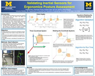
Figure 2: Graphical depiction of
the Euler Angle rotations about
the x, y, and z axis. These three
matrices are used to find the
orientations between the
segment coordinate system
(SCS) to the provisional
coordinate system (PCS) ,PCS
to the global coordinate system
(GCS), and unknown SCS to
GCS for each timeframe.
Figure 3: depicts the relationship between the 3 coordinate system
used in the algorithm, namely:
1. Provisional Coordinate System (PCS) computed from 3
arbitrary markers on the body segment
2. Global Coordinate System (GCS) which is the native lab
coordinate system,
3. unknown Segment Coordinate System (SCS) which
represents the orientation of the body segment.
Three Coordinate System
Figure 4: SCS rotations about the X, Y and Z axes relative to the
GCS and relative to the PCS represented as Euler rotation
matrices were used to yield body segment rotations relative to
the global frame.
Figure 5: PCS rotations about the X, Y and Z axes relative to the
GCS and relative to SCS represented as Euler rotation matrices
were used to yield PCS rotations relative to the global frame.
Relating the Coordinate Systems
Equations Relating the
Coordinate Systems
Figure 6: The validation algorithm seeks to find the
fixed relationship between the SCS and the PCS and
represent that relationship as the matrix Rps. The
matrix, Rps, is constant value and later on will be
used to find the unknown rotation matrix Rsg, which
relates the SCS to GCS.
Figure 7: Once Rps is found, it is used as a
constant in another algorithm to compute the
unknown Rsg matrix, which relates the SCS to
GCS.
Euler Angles