SI Units and Engineering Concepts Explained
•
2 likes•1,535 views

The document contains sample tasks and answers related to engineering concepts. Task 1 covers SI base units, derived units, and unit conversions. Task 2 discusses qualitative and quantitative research methods. Task 3 provides examples of qualitative and quantitative case studies. Subsequent tasks cover topics such as forces, moments, shear force diagrams, bending moment diagrams, buoyancy, material properties, heat transfer, electrical circuits, and more. The document serves as a reference for various engineering calculations and concepts.

Recommended
Recommended
More Related Content
Similar to SI Units and Engineering Concepts Explained
Similar to SI Units and Engineering Concepts Explained (20)
More from All Assignment Experts
More from All Assignment Experts (8)
Recently uploaded
Recently uploaded (20)
SI Units and Engineering Concepts Explained
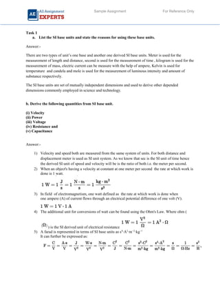
- 1. Sample Assignment For Reference Only Task 1 a. List the SI base units and state the reasons for using these base units. Answer:- There are two types of unit’s one base and another one derived SI base units. Meter is used for the measurement of length and distance, second is used for the measurement of time , kilogram is used for the measurement of mass, electric current can be measure with the help of ampere, Kelvin is used for temperature and candela and mole is used for the measurement of luminous intensity and amount of substance respectively. The SI base units are set of mutually independent dimensions and used to derive other depended dimensions commonly employed in science and technology. b. Derive the following quantities from SI base unit. (i) Velocity (ii) Power (iii) Voltage (iv) Resistance and (v) Capacitance Answer:- 1) Velocity and speed both are measured from the same system of units. For both distance and displacement meter is used as SI unit system. As we know that sec is the SI unit of time hence the derived SI unit of speed and velocity will be is the ratio of both i.e. the meter per second. 2) When an object's having a velocity at constant at one meter per second the rate at which work is done is 1 watt. 3) In field of electromagnetism, one watt defined as the rate at which work is done when one ampere (A) of current flows through an electrical potential difference of one volt (V). 4) The additional unit for conversions of watt can be found using the Ohm's Law. Where ohm ( ) is the SI derived unit of electrical resistance 5) A farad is represented in terms of SI base units as s4 ⋅A2 ⋅m−2 ⋅kg−1 It can further be expressed as:
- 2. Sample Assignment For Reference Only where F = farad, A = ampere, V = volt, C = coulomb, J = joule, m = metre, N = Newton, s = second, W = watt, kg = kilogram, Ω = ohm, H = henry. C. State the reasons for of using SI prefixes in dealing with engineering design. Answer:- Below are the several reasons why SI is prefixed is preferred. 1. The Main goal to define precise system of standards rather based on the individual name and arbitrary names of human body. 2. These SI units are very important to interlink to derived other units without any conversion factor. 3. This system of SI is used commonly in most places around the world, so that our standard fits the use of it and allows scientists from disparate regions to use a single without any confusion. d. Express the following: (i) 100245 uF in Farads (ii) 16.5 M Ω in K Ω (iii) 1495 kH in MHz (iv) 0.2025 Volts in mV (v) 125008 pF in uF Answer:- 1) As we know that uF in 1 farad is 1000000. We are converting between microfarad and farad uF or farad Farad is the derived SI unit for capacitance, hence 1 uF is equal to 1.0E-6 farad. That’s why 100245 Uf is 0.100245 2) 1 Kilo ohm (kΩ) is equal 0.001 Mega ohm (MΩ) 16.5 (MΩ)=0.0165(kΩ) 3) The frequency f in hertz (Hz) is equal to the frequency f in kilohertz (kHz) divided by 1000: f (MHz) = f(kHz) / 1000 Example Convert 1495 kilohertz to megahertz: f(MHz) = 1495kHz / 1000 = 1.495MHz 4.) 1 V = 103 mV = 1000 mV or 1 mV = 10-3 V = 0.001 V Volts to millivolts formula The voltage V in millivolts (mV) is equal to the voltage V in volts (V) times 1000: V(mV) = V(V) × 1000
- 3. Sample Assignment For Reference Only Example Convert 3 volts to millivolts: V(mV) = 0.2025 × 1000 = 202.5 mV 5.) How many uF in 1 pF? The answer is 1.0E-6. We assume you are converting between microfarad and puff. You can view more details on each measurement unit: uF or pF The SI derived unit for capacitance is the farad. 1 farad is equal to 1000000 uF, or 1000000000000 pF 125008 pf is equal to 0.125008 Uf. Task 2 Discuss the differences between qualitative and quantitative research methods that are employed in engineering design. Include two case studies in your answer. Answer:- There are two research approaches called as quantitative and qualitative. The quantitative methods are fairly inflexible with having surveys and questionnaires. Comparison of quantitative and qualitative research approaches overview general framework Analytical objectives Question format Data format Flexibility in study design Quantitative Seek to confirm hypotheses about phenomena Instruments use more rigid style of eliciting and categorizing responses to questions Use highly structured methods such as questionnaires, surveys, and structured observation To quantify variation To predict causal relationships To describe characteristics of a population Closed-ended Numerical (obtained by assigning numerical values to responses) Study design is stable from beginning to end Participant responses do not influence or determine how and which questions researchers ask next Study design is subject to statistical assumptions and conditions Qualitative Seek to explore phenomena Instruments use more flexible, iterative style of eliciting and categorizing responses to questions Use semi-structured methods such as in-depth interviews, focus groups, and participant observation To describe variation To describe and explain relationships To describe individual experiences To describe group norms Open-ended Textual (obtained from audiotapes, videotapes, and field notes) Some aspects of the study are flexible (for example, the addition, exclusion, or wording of particular interview questions) Participant responses affect how and which questions researchers ask next Study design is iterative, that is, data collection and research questions are adjusted according to what is learned 4 Qualitative methods are typically more flexible – that is, they allow greater spontaneity and adaptation of the interaction between the researcher and the study participant
- 4. Sample Assignment For Reference Only Task 3 Choose two different case studies, one involving qualitative data, one with quantitative data. Comment on the relative merits of each graphical representation and any improvements to the process that you would be able to recommend. Answer:- Qualitative data refers to limited data size for survey while quantitative data worked with large sample size with inflexibility. Just take two examples like survey about Smartphone users in particular region. If two Smartphone company doing research about their users in particular region will come under qualitative data research while if government organization do research about how many Smartphone users in that particular region then it comes under quantitative data research. Although both data analysis is good but depends upon requirement. Qualitative data is more precise and accurate as compare to quantitative since data sample is small but it’s a precise on up to certain level but as compare to quantitative research data, sample data is more and research process is more exhaustive but more accurate than previous one. Task 4 You are presented with scientific data by your senior engineer. He has asked you to present to an audience an analysis of the scientific data using both computational and qualitative methods using an appropriate software package. Task 5 A simply supported beam of length 6m supports a vertical point load of 45kN at a distance of 4m from one end. a. Determine the reaction forces at either end. b. Draw the shear force diagram c. Make appropriate calculations and draw the bending moment diagram d. Recalculate the reaction forces at either end, taking into account the actual weight of the beam as a UDL. Assume that the mass of the beam is 39Kg/m and g= 9.81 m/s2 . a) Reaction force at either end ∑Fx= R1 + R2= 45 KN ….eq(1) ∑M=0 Taking the moment about A R1 x 0 + 45 x 4 – R2 x 6= 0 45 x 4 = R2 x 6 R2= 45 x 4/6 = 30KN
- 5. Sample Assignment For Reference Only Putting the value of R2 in equation (1)we get R1 R1 + R2 = 45 R1 = 45-30 =15KN b) Shear force Diagram Shear force calculation:- S.F at A = +15 KN S.F at C= +15 – 45 = -30KN S.F at B= -30KN c) Bending Moment Diagram & Calculation:- B.M Between point A to C (0 ≤ x ≤4) B.M = R1 x X B.M at point A = 15 x 0 =0KN-m B.M at point C= 15 x 4 = 60KN-m B.M between point C to B (4 ≤ x ≤6) B.M = R1 x X – 45 x (X-4) B.M at point C = 15 x 4- 45 (4-4) {X=4} B.M at point B = 15 x 6 – 45 (6-4) = 90 -90 = 0KN-M D) When Load type in UDL UDL = 39 x 9.81= 382.59 N/M Reaction force Calculations ∑Fv= R1+R2= 382.59 x 6 = 2295.54N
- 6. Sample Assignment For Reference Only ∑Mx = 0 Taking moment about A R1 x 0 + 2295.54 x 3 – R2 x 6 = 0 R2 = 2295.54 x 3/ 62 = 1147.77N R1 = 1147.77N Shear force calculation S.F = 1147.77-382.59 x X S.F at A = 1147.77-382.59 x 0 = 1147.77 N S.F at B= 1147.77-382.54 x 6 = -1147.77N S.F at C= 1147.77-382.59 x 3= 0N B.M calculation B.Ma =R1 x X- 382.59 x X x X/2 B.Ma = 0 {x=0} B.Mb = 1147.77 x 6 -382.59 x 6 x 3= 0 N-M B.Mc = 1147.77 x 3 – 382.59 x 9/2 = 3443.31 Task 6 a. Explain the principle of buoyancy? b. Briefly discuss two engineering applications of buoyancy? Answer:- a) The Buoyancy principle is very important principal where be a found the buoyant force exerted in body is emerge in a fluid fully and partially. It straight that weight of the fluid the body displaced and act the upward direction center of mass displaced fluid whether fully and partially submerge. b) The best two engg. Application of buoyancy is Submarine floated in the sea and hot air balloon rises in the sky. Submarine is a best example where be co related the submarine movement in the water to the principal of buoyancy. in the same way hot air balloon rises and float in the sky due to the buoyancy force. Task 7
- 7. Sample Assignment For Reference Only Discuss briefly the temperature effects on mechanical properties such as a dimensional change, elasto-plastic changes, due to thermal stresses. Answer:- Steel is best material and good example to understand the temperature effect on it. When mild steel or structural steel is without having any thermal loads they will have ability to perform elastic behavior under certain circumstances. As soon as the thermal load is applied on the body then body try to changes the behavior of structure may be due to conduction and temperature effects. Initially due to the less the value of conduction body can retract its elastic behavior when thermal load is removed but as soon as thermal loads are increasing then body behavior tends to go into plastic stage of material where body can’t retract its shape and size even after load in removed. Parallel thermal stresses also acting on the subject to change the condition of mild steel When thermal loads are into picture. Best example is iron rod when subjected to high intensity thermal loads in form or heating or conduction then rod may changes its shape and size by changing its behavior from elastic to plastic condition. Task 8 a. Find the acceleration which will be produced in a body having mass 60 kg when a force of 150 N acts on this body by using D’ Alembert’s Principle. b. A cylinder having a mass of 4000 kg, radius 1.0 m and a moment of inertia about its axis of 3000 kg m2 , is rolled from rest along a horizontal plane as a result of 800 N being applied by a rope at its circumference. Determine the resulting linear acceleration of the cylinder. Task 9 For a domestic hot water system, a copper pipe carries hot water at 70 0c and has an external diameter of 150 mm and is lagged to an overall diameter of 500 mm. If the surface temperature of the lagging is 20 0C determine the rate of heat loss per meter. Task 10 Electrical engineering materials can be categorized as conductors, semi conductors and insulators. Use the electron configuration of atom to predict the electrical and magnetic behavior of substance. There are various engineering Materials use as a conductor and semi conductor and insulators. There uses depend upon electrical & magnetic behaviors of substance so these play very important role in electrical engineering stream and conductor, semi-conductor & insulator can manufactured by special kind of material depends upon application and utilization. Task 11 Describe the conditions that cause the physical, chemical and biological degradation of materials and how materials degrade in certain conditions. Materials Degradation of materials has always been one of the major thrust areas of the department. Interaction of environment with the materials, like corrosion, stress corrosion cracking, hot corrosion, etc. is extremely important for final use of materials in different structural applications. The department is also involved in coatings of different classes to enhance the corrosion and wear resistance. The main thrusts are
- 8. Sample Assignment For Reference Only (i) Effect of corrosive, (ii) Effect of stress, (iii) Effect of composition and microstructure, (iv) Bulk and surface modification to enhance the corrosion resistance. Task 12 Discuss the magnetic behavior of steel under the influence of mechanical stress. When steel is subjected under mechanical stress and enclosed with magnetic waves and magnetic field then steel goes under rapid movement of stresses from elastic to plastic movement there was reducing the mechanical stress. Due to magnetic field steel subjected under load get additional strength there by resisting the applied load reducing the mechanical stresses. Task 13 Discuss the behavioral characteristics of certain mechanical systems that can be affected by the changes in the thermal efficiency of heat transfer process. Behavior studies of certain mechanical system are playing vital role in the overall study of study thermal efficiency of heat mass transfer. Due to heat transfer process material can contract & expend. Due to heat transfer process material can goes under plastic and elastic behavior and it further depend intensity of heat, further factors like mechanical stress, thermal stress then yield strength resilience come into picture Task 14 (a) For the network shown in Fig 2.0, determine i. Thevenin’s equivalent circuit ii. Norton’s equivalent circuit. iii. The current flowing in the 4 Ω resistors. iv. Assume that the battery has negligible internal resistance. (b) Use the superposition theorem to find currents I, I2 and I3 of Fig 3.0
- 9. Sample Assignment For Reference Only Task 15 (a) Construct a graph of the spectrum for each waveform in Fig 4.0 A = 10 V. Fig 4.0 (b) A complex waveform is described by the equation V = 100sin (100Πt) + 50sin (200Πt -Π/2). Determine graphically the shape of the waveform and estimate the peak-peak voltage.
- 10. Sample Assignment For Reference Only Task 16 Fig 5.0 (a) A coil of inductance 74 mH and resistance 28 ohms in series with a 50uF capacitor is connected to a 250 V, 50 Hz supply. Calculate : i. The impedance ii. The current flowing iii. The phase different between voltage and current iv. The voltage across the coil v. The voltage across the capacitor. vi. Sketch the phasor diagram (b) A coil of resistance 25 Ω and inductance 100 mH is connected series with 0.12 uf capacitor across a 120 V,variable frequency supply. If R is small compare with XL as in radio circuits, Determine : (i) The resonant frequency
- 11. Sample Assignment For Reference Only (ii) The dynamic resistance (iii) The current at resonance (iv) Tthe Q - factor at resonance Task 17 (a) Explain the operation of a transformer using the principles of electromagnetic induction. (b) A 300 kVA transformer has a primary winding resistance of 0.4 Ω and a secondary winding resistance of 0.0015 Ω. The iron loss is 2 kW and the primary and secondary voltages are 4 kV and 200 V respectively. If the power factor of the load is 0.78, determine the efficiency of the transformer on full load D4 Critically evaluate different techniques used to solve problems on Series parallel R, L, C circuits using A.C. theory. Task 18 (a) Refer to the circuit shown in Fig 6.0 Fig 6.0
- 12. Sample Assignment For Reference Only R = 60 ohms, L = 318.4 mH, C= 15 uF, V= 200V, 50 Hz. Calculate : (i) The current in the coil (ii) The current in the capacitor (iii) The supply voltage and its phase angle (iv) The circuit impedance (v) Sketch the phasor diagram (b) Validate the results using simulation packages.