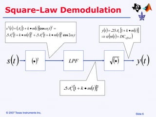
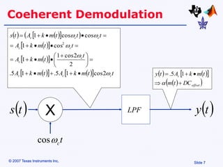
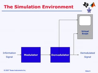
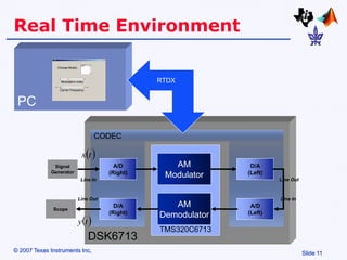
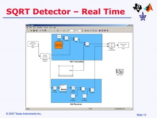
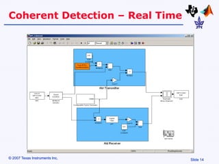
Slide 1
© 2007 Texas Instruments Inc,
Amplitude Modulation
• Amplitude Modulation is a process where the
amplitude of a carrier signal is altered according to
information in a message signal.
• The frequency of the carrier signal is usually much
greater than the highest frequency of the input
message signal.
Slide 3
© 2007 Texas Instruments Inc,
AM – Basic Definitions (cont.)
The Envelope:
The AM Signal
   
  t
t
m
k
A
t
s c
c 
cos


 1
   
 
t
m
k
A
t
s c 

 1
0 0.02 0.04 0.06 0.08 0.1 0.12 0.14 0.16 0.18 0.2
-5
-4
-3
-2
-1
0
1
2
3
4
5
Slide 4
© 2007 Texas Instruments Inc,
The AM Spectrum
0 500 1000 1500 2000 2500 3000 3500 4000 4500 5000
0
0.5
1
1.5
Frequency (Hz)
|M(f)|
0 500 1000 1500 2000 2500 3000 3500 4000 4500 5000
0
0.5
1
1.5
Frequency (Hz)
|Y(f)|
 
t
m  
t
s
Carrier
Side
Bands
Slide 5
© 2007 Texas Instruments Inc,
AM Modulation Scheme
t
A c
c 
cos k
1
 
t
m  
t
s
+ X
k
Slide 6
© 2007 Texas Instruments Inc,
Square-Law Demodulation
 2

   
 
 
 
   
  t
t
m
k
A
t
m
k
A
t
t
m
k
A
t
s
c
c
c
c
c


2
1
5
1
5
1
2
2
2
2
2
2
cos
.
.
cos









LPF  

 
t
s
   
 
 
 
offset
c
DC
t
m
t
m
k
A
t
y






1
25
.
 
 2
2
1
5 t
m
k
Ac 

.
 
t
y
Slide 7
© 2007 Texas Instruments Inc,
Coeherent Demodulation
t
c

cos
   
 
 
 
 
 
 
 
   
  t
t
m
k
A
t
m
k
A
t
t
m
k
A
t
t
m
k
A
t
t
t
m
k
A
t
s
c
c
c
c
c
c
c
c
c
c





2
cos
1
5
.
1
5
.
2
2
cos
1
1
cos
1
cos
cos
1
2











 














LPF
 
t
s
   
 
 
 
offset
c
DC
t
m
t
m
k
A
t
y






1
5
.
 
t
y
X
Slide 8
© 2007 Texas Instruments Inc,
Hands-On
• Simulation
• Implementation using the DSK6713
Slide 9
© 2007 Texas Instruments Inc,
The Simulation Environment
Modulator
Virtual
Scope
Demodulator
Information
Signal
Demodulated
Signal
Slide 10
© 2007 Texas Instruments Inc,
The Simulation Environment
Slide 11
© 2007 Texas Instruments Inc,
Real Time Environment
DSK6713
CODEC
TMS320C6713
AM
Modulator
D/A
(Left)
AM
Demodulator
A/D
(Left)
A/D
(Right)
D/A
(Right)
 
t
s
 
t
y
Line In
Line In
Line Out
Line Out
Signal
Generator
Scope
PC
RTDX
Slide 12
© 2007 Texas Instruments Inc,
GUI
Slide 13
© 2007 Texas Instruments Inc,
SQRT Detector – Real Time
Slide 14
© 2007 Texas Instruments Inc,
Coherent Detection – Real Time
Slide 15
© 2007 Texas Instruments Inc,
Configurable Carrier










n
f
f
j
s
c
s
c
s
c
e
n
f
f
nT



2
Re
2
cos
cos

Amplitude Modulation.ppt

  • 1.
    Slide 1 © 2007Texas Instruments Inc, Amplitude Modulation • Amplitude Modulation is a process where the amplitude of a carrier signal is altered according to information in a message signal. • The frequency of the carrier signal is usually much greater than the highest frequency of the input message signal.
  • 2.
    Slide 3 © 2007Texas Instruments Inc, AM – Basic Definitions (cont.) The Envelope: The AM Signal       t t m k A t s c c  cos    1       t m k A t s c    1 0 0.02 0.04 0.06 0.08 0.1 0.12 0.14 0.16 0.18 0.2 -5 -4 -3 -2 -1 0 1 2 3 4 5
  • 3.
    Slide 4 © 2007Texas Instruments Inc, The AM Spectrum 0 500 1000 1500 2000 2500 3000 3500 4000 4500 5000 0 0.5 1 1.5 Frequency (Hz) |M(f)| 0 500 1000 1500 2000 2500 3000 3500 4000 4500 5000 0 0.5 1 1.5 Frequency (Hz) |Y(f)|   t m   t s Carrier Side Bands
  • 4.
    Slide 5 © 2007Texas Instruments Inc, AM Modulation Scheme t A c c  cos k 1   t m   t s + X k
  • 5.
    Slide 6 © 2007Texas Instruments Inc, Square-Law Demodulation  2                  t t m k A t m k A t t m k A t s c c c c c   2 1 5 1 5 1 2 2 2 2 2 2 cos . . cos          LPF      t s           offset c DC t m t m k A t y       1 25 .    2 2 1 5 t m k Ac   .   t y
  • 6.
    Slide 7 © 2007Texas Instruments Inc, Coeherent Demodulation t c  cos                         t t m k A t m k A t t m k A t t m k A t t t m k A t s c c c c c c c c c c      2 cos 1 5 . 1 5 . 2 2 cos 1 1 cos 1 cos cos 1 2                            LPF   t s           offset c DC t m t m k A t y       1 5 .   t y X
  • 7.
    Slide 8 © 2007Texas Instruments Inc, Hands-On • Simulation • Implementation using the DSK6713
  • 8.
    Slide 9 © 2007Texas Instruments Inc, The Simulation Environment Modulator Virtual Scope Demodulator Information Signal Demodulated Signal
  • 9.
    Slide 10 © 2007Texas Instruments Inc, The Simulation Environment
  • 10.
    Slide 11 © 2007Texas Instruments Inc, Real Time Environment DSK6713 CODEC TMS320C6713 AM Modulator D/A (Left) AM Demodulator A/D (Left) A/D (Right) D/A (Right)   t s   t y Line In Line In Line Out Line Out Signal Generator Scope PC RTDX
  • 11.
    Slide 12 © 2007Texas Instruments Inc, GUI
  • 12.
    Slide 13 © 2007Texas Instruments Inc, SQRT Detector – Real Time
  • 13.
    Slide 14 © 2007Texas Instruments Inc, Coherent Detection – Real Time
  • 14.
    Slide 15 © 2007Texas Instruments Inc, Configurable Carrier           n f f j s c s c s c e n f f nT    2 Re 2 cos cos