Introduction to IEEE STANDARDS and its different types.pptx
US4750965.pdf
1. United States Patent (19)
Pippel et al.
54
(75)
73
ADAPTIVE CONTROL FORTAPE LAYING
HEAD HAVING NATURAL PATH
GENERATION
Inventors: James J. Pippel; Bernd A. K.
Messner, both ofRockford, Ill.
Assignee: The Ingersoll MillingMachine
Company, Rockford, Ill.
21 Appl. No.: 845,858
(22 Filed: Mar. 28, 1986
51) Int. Cl." .............................................. B32B 31/00
52 U.S. C. .................................... 156/361; 156/523;
156/574; 156/577; 364/150,364/474
58 Field ofSearch ............... 156/361,574, 577, 523;
364/150, 474
(56) References Cited
U.S. PATENT DOCUMENTS
Re. 30,016 5/1979 Hohn................................... 364/474
3,560,308 2/1971 Buck .................................... 156/522
3,574,040 4/1971 Chitwood et al. ... 156/350 X
3,577,297 5/1971 Howard .............................. 156/522
3,577,303 5/1971 Buck .................................... 156/522
3,607,572 9/1971 Jorgensen . ... 156/505
3,625,799 12/1971 Way ............... ... 156/530
3,752,728 8/1973 Smirnov et al. .................... 156/577
3,775,060 1 1/1973 Courtois et al. 23/253 R.
3,775,219 11/1973 Karlson et al. .... ... 156/363
3,810,805 5/1974 Goldsworthy et al. ... 156/361
3,939,034 2/1976 Tanaka et al. ...................... 56/522
3,970,831 7/1976 Hegyi ............. 156/363 X
3,992,244 11/1976 Craig et al. ......................... 156/521
3,997,387 12/1976 Yamaguchi et al. ................ 56/59
4,011,437 3/1977 Hohn .............................. 235/151.11
4,133,711 1/1979 August et al........................ 156/353
4,180,181 12/1979 Brandwein . ... 221/70
4,182,645 l/1980 Hill ...................................... 156/36
4,208,238 6/1980 August et al........................ 156/523
4,259,144 3/1981 Ballentine ........................... 156/523
4,285,752 8/1981 Higgins .......... ... 156/522 X
4,292,108 9/1981 Weiss et al. ......................... 156/361
4,328,061 4/1982 Offet al. ............................. 156/353
4,328,062 5/1982 Offet al. ... ... 156/361 X
4,330,357 5/1982 Collins ................................ 156/584
4,338,659 7/1982 Kurakake ............................ 364/150
4,351,688 9/1982 Weiss et al. ......................... 156/523
SS
o
see SO2
NSSa
ŠII
11 Patent Number: 4,750,965
(45) Date of Patent: Jun. 14, 1988
4,370,721 1/1983 Berenberg et al. ................. 364/474
4,382,836 5/1983 Frank .............................. 156/522 X
4,419,170 12/1983 Blad ................................ 156/361 X
4,453,221 6/1984 Davis et al. ......................... 364/474
4,491,906 1/1985 Kishi et al. ..... ... 364/300
4,506,335 3/1985 Magnuson ........................... 364/174
4,516,461 5/1985 Schaeffer ... ... 83/563 X
4,531,998 7/1985 Peterson .............................. 156/574
4,557,783 12/1985 Grone et al. ... 56/523 X
4,557,790 12/1985 Wisbey ................................ 156/511
4,569,716 2/1986 Pugh ................................... 156/510
4,591,402 5/1986 Evans et al. ........................ 156/574
4,598,380 7/1986 Holmes et al. .
4,601,775 7/1986 Grone ............ m 156/523
4,627,886 12/1986 Grone et al. ........................ 156/574
4,634,946 1/1987 Moulds et al. ...................... 364/150
4,663,703 5/1987 Axelby et al. ....................... 364/150
FOREIGN PATENT DOCUMENTS
2083658 3/1982 United Kingdom ................ 364/474
OTHER PUBLICATIONS
“Natural Path Report', 2-52700/4AVO-167 (covered
by letter of 15 Oct., 1984).
"ATLM Post-Processor Requirements' Report,
2-52700/4AVO-196 (covered by letter of 13 Nov.,
1984).
Primary Examiner-Jerome Massie
Attorney, Agent, or Firm-Fitch, Even, Tabin &
Flannery
(57) ABSTRACT
Atapelayingmachinefordepositingcompositetapeon
thesurface ofa mandrel havinga tapelaying head posi
tionable in multiple axes by a linear interpolative feed
back control in combination with an adaptive control.
The feedback control receives a commanded position
from a natural path part program and regulates motion
of the tape laying head of the machine along a track
which will not unequally tension the edges of the tape
and which is highly reproducible. Theadaptive control
separately varies the motion produced along individual
axes by the feedback control without changing the
tracking path to ensure correct tape laying conditions.
15 Claims, 15 Drawing Sheets
Š O
2S
N.A to
RFA
11. U.S. Patent Jun.14,1988 Sheet10of15 4,750,965
2ZZ O
GS3S232
7
/
NZSZSZS2S25 Y ZZ
loo-Y/1//
STS
NNNER RN
94.2S2S2SZSSN95's Ato
ÉS4S4S4N4N2Rivertical
F. G. 4
13. U.S. Patent Jun.14,1988 Sheet12of15 4,750,965
APT PART
PROGRAMS
3.28
SURFACE
AND
PERPHERY IN 322 33O
DATA / )
336 GENERATION PROCESSOR
324
PLY TELECOM GRAPH CS
GRAPH CS PROGRAM TERM NAL
332 33
PROCESSOR PART PROGRAM
- - - - - - - - - - GENERATOR
34 OR
INTERACE INTRACE TELEcoM 138
TAP
PUNCH DRIVE INTERFACE
P 32
PUNCH T
TAP 2
A
PROGRAM 35
- - - - - - - -
CONTROL
PROCESSOR
3O4. CONTROLLER 3OO
STORAGE sERvo Loops CONTROL
OPART NC PROCESS ADAPTIVE
PROGRAMS
oSYSTEM
PROGRAMS
ED TOR FEEDBAck
POSITON
TERMINA
o NPUT
A CONTROL
GRAPHICS A B CODE 3O2
C C DATA Q C
3O5 LOG COMPUTER
22
3O9
TAPE
SUR PER FIG. 6
DATA
15. U.S. Patent Jun. 14, 1988
2F z-axis CONTROLLER OO in
ADAPTIVE
SENSOR
A AXIS
ADAPTIVE NPUT OUTPUT
OR 454. CONTROL
3" 482
A - AXIS
ADAPTIVE
SENSOR
456 494
Abaje A
SENSOR
6" 458
A AXIS 496
ADAPTIVE O C-AXS" .
SENSOR Avt. 5A U SERVO
46O || 8 | 498
C-AXIS - U N N U X-AXIS
ARAM T V V HT
462 SENSOR E E SERVO
M M 5OO
C-AXIS E U Y-AXIS
464L SENSOR
48O 488
466 to AXIS AXS
POSITION SERVO
POSITON 5O4
NSCR PROCESSOR
X-AX S
Sos SN D. GITAL
SENSOR PORT 5O6
C-AX S -----|--|--|---------
472POSTION
SENSOR
474 A-AX S
POST ON 3O4.
SENSOR - - - - - - - - - - - - -
-
- X-AX S Ya AXIS -AXIS A-AXIS C-AXIS
COMMAND COMMAND COMMAND COMMAND COMMAND
L- 508 5 O 52 54 56 -
F.G. 7
Sheet 14 of 15 4,750,965
17. 4,750,965
1.
ADAPTIVE CONTROL FORTAPE LAYING HEAD
HAVING NATURAL PATH GENERATION
This invention relates to an adjunctadaptive or reac
tive control of a tape laying head which is prepro
grammed for the deposition ofcomposite tape along its
natural path upon a surface ofcompound curvature.
BACKGROUND OF THE INVENTION
In thecontextofthisinvention, theterm "composite'
describes a material consisting essentially of high
strength fibers or filaments ofgraphite, or other mate
rial, embedded in a matrix of a thermosetting resin
which serves when cured to maintain the alignment of
the fibers and their relationship to one another within
the matrix as the material is stressed. As applied to the
construction ofaerodynamic surfaces, composite mate
rial hasheretofore taken the form ofwoven matspreim
pregnated with resin and, more recently, resin tapes
embedded with fibers or filaments aligned in the longi
tudinal direction ofthe tape, multiple courses ofwhich
are laid side by side to construct one ply or layer ofa
manufactured article which is then constructed incre
mentally ofsuccessive layers oftape.
The application of these construction techniques to
contoured surfaces heretofore has been essentially one
offirst laying up the laminated structure on a flat sur
face and then transferring or pressing the layup into a
mold having the final contour of the part to be fabri
cated so that the layup will assume the desired shape.
The mold with the composite layup applied thereto is
then autoclaved. The layers ofresinous matrix material
merge intoa unitarystructure duringtheinitial stagesof
the process and then solidify upon continued exposure
to the high temperature in the autoclave as the resin
CS
The described system poses a number ofproblems in
the molding of surfaces of compound curvature i.e.,
those curved in multipleplanes or on multipleaxes. One
problem is conforming a plane table layup to the com
pound surface of a mold and this problem becomes
more prominent with the severity of the curvature en
countered. In all cases, irrespective of curvature, the
mere necessity oftransferring the layup from a flat lay
surface to a mold and pressing it into conformity with
the mold surface is a labor-intensive and time-consum
ing operation.
It is accordingly desirable from the standpoint of
manufacturing efficiency and the integrity of the final
product to form the laminated layup with composite
tape laid directly upon the compound surface of an
appropriatelyshaped toolormandrel.Thisispreferably
donewith compositetapeto make the mostefficientuse
of the strength of the fibrous material, as well as to
conform the essentially planar form of the building
material more readilyto thecompound curvatureofthe
mandrel. Such conformance is much more easily ac
complished with composite tape than by the use of
broad goods.
Even with composite tape, however, the practical
necessity ofworking with tapes of finite widths in the
range of from 1 to 6 inches and thicknesses of about
0.0055 to 0.010 inches, and the essential inelasticity of
thefibercoreofthetape underlayingconditions, create
their own problems. The primary difficulty is conform
ing the composite tape to the compound surface with
out puckering one edge or the other of the tape as the
5
O
15
25
30
35
40
45
50
55
60
65
2
tapelaying mechanism follows, within limits, the curva
ture of the lay surface on any selected tape course.
To overcome this problem, it has been proposed, as
disclosed in U.S. Pat. No. 4,696,707, entitled "COM
POSITE TAPE PLACEMENT APPARATUS
WITH NATURAL PATH GENERATION
MEANS' and issued to Lewis et al., which is com
monly assigned with this invention, that any given lay
surface first be defined mathematically with respect to
the tapelaying machine coordinate system, and thatthe
tapebe applied tosuch a surface byfollowinga prepro
grammed natural path of the tape thereon while con
forming as nearly as possible to the direction in which
the designerwould prefer to have the fibers aligned for
the sake of the strength of the part. By the technique
disclosed in Lewis et al., the path of each successive
coursewithin a ply,and eachsuccessiveplyin thelayup
ofthe laminated article, is predetermined such that the
machineisprogrammed to laythetape withouttension
ing the tape edges unequally. Thisavoids the puckering
ofthe tapealong either ofits edges as would inevitably
happen ifthelaying mechanism sought tosteer the tape
forcibly to any substantial degree away from its natural
path.
To rapidly and accurately generate a natural tape
path for a part program, the programmed machine of
Lewis et al. uses a mathematical description ofthe lay
surface onthe workpiecearea ofa mandrel formingthe
complex contoured shape. This mathematical descrip
tion ofthe lay surface describes the shape and contours
of the mandrel in terms of various Z-axis heights or
offsetsfrom a control planebroken intoconvenient X-Y
areas. Because it is the tape laying head ofthe machine
which is to be moved, the X-Y areas of the control
plane are referenced not to the actual coordinates in
space of the surface of the mandrel but to the internal
coordinate system of the tape laying machine. There
fore, there is at least one area ofconcern in laying tape
precisely on the mandrel which must be addressed to
enhance the rapid manufacture ofparts in this manner.
The problem which must be overcome for the preci
sionproductionoflayeredparts isthatthemandrel may
not exactly conform to the mathematical description
used to generate the natural path part program. There
are many reasons for a discrepancy between the actual
surfaceand the mathematical description thereof. Some
ofthe most prevalent reasonsincludean approximation
ofthe surface in the first instance, the inability to manu
facture two mandrel surfaces exactly the same, and
changes in the mandrel surface dueto tape laying envi
ronment such as wear, warpage, etc.
When making the mathematical description ofa man
drel surface in the first instance, the description ofthe
actual surface must be an approximation to some de
gree. The more surface points that the description uses
the better the approximation will be, but it is still an
approximation. Moreover, ifone uses less points, some
sacrifice in accuracy will be seen but at the gain of
production rates as less surface points have to be ac
countedforbytapehead movement. Becauseofthesize
and complexity ofthe mandrels used in the production
process, no two can have exactly the same surface. An
ideal ordesigned mandrel surface, astandard, is used to
make the mathematical description by digitization or
the like. The amount by which other actual mandrels
differ from this standard will cause errors in the tape
laying process. However, this process allows mandrels
18. 4,750,965
3
to be interchangeable from part to part and from pro
duction facility to production facility.
Moreover, each mandrel surface will change in the
ordinary course of production over time because of
different environmental conditions such as expansion or
contraction, wear, and warpage. Additionally, when
makingapartofmany layers, themathematical descrip
tion assumes that each ply is a constant thickness and
changes the description accordingly. The composite
tapeonan averageis a nominal thicknessbuteach plyis
different and changes theactual surface from the origi
nal representation by a small amount. Although each
actual change may be extremely small, some changes
tend to accumulate and with the use ofthe same part
program for different mandrels, there may be changes
that occur in different directions which exacerbate an
attempt for remedy.
Adaptive control has been suggested as a solution to
theproblemofdeviations oftheactual surface from the
representative surface. Previous attempts to lay com
posite tape on a complex contourby seeking to control
the laypath direction completelybyadaptivesensing of
the tool surface have encountered significant problems.
One problem with prior adaptive approaches has
been the selecting ofcontrol gains and authority levels
for the control. Ifthe control is made sensitive enough
to respond to slight variations in surface imperfection,
then, at the velocities and gains needed for this preci
sion, the control becomes oscillatory and unstable and
will not settle readily into a smooth motion such that
composite tape can be correctly laid. Alternatively, if
-the gain and authority of the control is reduced signifi
cantly, then the lack of precision that the tape layer
displaysin following a correct path fails to produce the
-desired quality in the parts. The only ready answer to
this problem is to slow the machine to production rates
which are unacceptable, i.e., to trade off productivity
for control.
Further, for multi-axis tape laying machines simulta
neousadaptive control ofall axes has not been advanta
1geous. The coupling ofall the adaptive inputs into one
control algorithm has proven unworkable because the
interaction between separate axes is not readily defin
able. Without a precise definition ofthe complex cou
pling mechanisms between movements, an integrated
adaptivecontrol cannotachieve theprecision necessary
for tape laying machines.
Another problem which is inherent in the previous
adaptive approaches and which cannot be readily
solved is the basic nonreproducibility of the parts. Be
cause prior adaptive controls continue to hunt along a
tape course path and doso in an unpredictable manner,
every part made by this method, even on the same tool
surface, will be different from any other part. There
fore, quality control and reproducibility of precision
parts has not been obtainable by adaptive methods.
The natural path control set forth in Lewis et al.
solves the quality control problem by precisely and
reproduciblygeneratinga programmed path fora com
posite tape laying head which will produce complex
contoured parts with facility. Because it is desirable to
retain the exact tracking path from part to part, devia
tions of the actual surface from the mathematical de
scription which is used to calculate the natural path are
not compensated by the part program.
It is now known that differences between the mathe
matical representation of the mandrel surface and the
actual surface tend to cause more problems in the area
5
10
15
20
25
30
35
45
SO
55
4
of the quality of the tape lay, i.e., whether the tape
course is properly adhered to the underlying surface,
than in course path tracking. Therefore, adaptive con
trols which do not affect the tracking path but affect
only the tape laying conditions can provide gains in the
qualityofthetape laying.Thecorrectlayingconditions
for composite tape are a substantially constant pressure
on the tape with the pressure being applied by a roller
surface substantially flat against the contour ofthe tool
surface, and with the tape directly under the roller
surface. An adaptive control system which can correct
for actual variations in the tool surface without chang
ing the natural tracking path of the machine would be
advantageous because the reproducibility and speed of
the natural path control would be retained while insur
ing that the composite tape waslaid under the optimum
conditions.
The adaptive controlsystem ofthe present invention
is adapted to be superimposed upon a preprogrammed
natural path for a tape laying head for the sake ofdeal
ing with discrepancies between the part program and
the actual lay surface as it is encountered by the tape
laying head in action. Such discrepancies, depending
upon their nature, may call for independent local or
transient adaptive adjustments of the tape laying head
on one or more ofits axes of movement without deviat
ing from the natural tracking path.
SUMMARY OF THE INVENTION
Theinvention providesan adaptivecontrol to modify
the preprogrammed natural path movement ofa multi
axis tape laying machine employed in the manufacture
of composite articles of compound curvature. The
adaptive control compensates only for the variations in
tape laying conditions caused by the actual surface of
thetoolbeingdifferentfrom themathematical represen
tation used for generating the natural path. In the pre
ferred arrangement, theadaptive control independently
modifies several ofthe tape head movements along the
preprogrammed path without changing the tracking
path.
In general, the tape laying head of a machine is
moved in three linear dimensions X, Y, and Z and two
rotational dimensionsAand C with a control according
to a preprogrammed natural path part program. A seg
mented laydown roller is provided to maintain a sub
stantiallyconstant pressure on thecomposite tapeas itis
laid so that it will adhere properly to an underlying
surface. The control ofthe roller assembly requires that
the rollers are maintained in contact with the surface,
are parallel to the surface contour, and squarely track
the lay ofthe composite tape. Adaptive control means
are provided to generate signals which are superim
posed on the control signals ofthe natural path tracking
so that these tape laying criteria are met.
The adaptive control includes means for sensing any
sideward deviation ofthe composite tape from its nor
mal path centered beneath the plurality of laydown
roller segments which would indicate that the machine
is being steered in a direction other than that which the
tapeseeksto follow.Thesensing ofsuch deviation calls
for theturning ofthe tape head on its vertical or C-axis
to align the head with the axis ofthe natural tape path.
The adaptive control further contemplates the sens
ing of any differential deflection of segments of the
laydown roller to detect any divergence ofthe horizon
tal tilt of the tape laying head from that normal to the
lay surface in making a "side hill' or "cross contour'
19. 4,750,965
5
lay. The signals generated by such sensors are used to
adjust the rotation ofthe tape head on a horizontal, or
A-axis, to balance the deflection of the outermost seg
ments ofthe laydown roller so as to maintain the roller
surface parallel to the mandrel surface.
Similarly, in addition to restoring a balanced deflec
tion across thesegments ofthe laydown rollerby tilting
the tape laying head on its A-axis, the deflection of a
central segment of the laydown roller is employed by
the adaptive control to raise or lower the entire tape
laying head via a vertical or Z-axis movement to main
tain contact with the mandrel surface. This adaptive
control keeps the roller surfaceand centerpoint ofthat
surfacefrom leaving thecenterlineofthe ram on which
the tape head is carried and the centerline of the "A"
axis pivot.
The adaptive control modifies the natural path con
trol to compensate for differences between the actual
mandrel surface and the representative surface which
affect the quality ofthe tape laying. The conditions of
the tape laying are corrected by the adaptive control
without disturbing the rapid and tightly controlled
movements of the tape laying head along the natural
path track. Therefore, the system provides reproduc
ibility for each part without any sacrifice in the quality
ofthe tape lay.
BRIEF OESCRIPTION OF THE DRAWINGS
The foregoing and other objects ofthe invention are
accomplished by the mechanism described and ex
plained in detail in the following specification which
should be read in conjunction with the accompanying
drawings wherein:
FIG. 1 is an elevational view of a multi-axis tape
laying machine having a gantry mounted tape laying
head for applying composite tape to a curved mandrel
surface;
FIG. 2 is a front elevational view of the oncoming
tape laying head illustrated in FIG. 1;
FIG. 3 is a right side elevational view of the tape
laying head illustrated in FIG. 1 with the tape laying
movement ofthe head proceeding from left to right;
FIG. 4isaleftsideelevational viewofthetape laying
head illustrated in FIG. 1 with the tape laying move
ment ofthe head proceeding from right to left;
FIG. 5isa fragmentary enlarged cross-sectional view
ofthesegmentedlaydown rollerofthetapelayinghead
taken verticallythrough the section line 5-5 illustrated
in FIG. 3;
FIG. 6is an underside view ofthe portion ofthetape
head illustrated in FIG. 5 taken along section line 6-6
of that figure;
FIG. 7 is a partially cross-sectioned, side elevational
viewofthelaydownrollersubassemblyofthetapehead
shown in neutral laying position;
FIG. 8is a top view ofthe laydown roller subassem
bly taken along the section line 8-8 of FIG. 7;
FIG.9 isasectional viewofthelaydown rollersubas
sembly taken at an intermediate level along section line
9-9 of FIG. 7;
FIG. 10 is a partially cross-sectioned front view of
the photodetector assembly and calibrating mechanism
used for the C-axis adaptive control illustrated in FIG.
7;
FIG. 11 isabottom viewofthephotodetectorassem
bly illustrated in FIG. 10;
FIG. 12 is a top view of a safety switch assembly
operated by the laydown roller illustrated in FIG. 7;
O
15
25
30
35
45
50
55
60
65
6
FIG. 13 is a side view taken along section line 13-13
in FIG. 7 illustrating two of the four photodetectors
used for A-axis adaptive control;
FIG. 13A is a functional representation ofthe outputs
ofthe photodetectors for different positions ofthe actu
ator arms sensed;
FIG. 13B is a pictorial representation of a photode
tector covered partially by the edge of the composite
tape;
FIG. 14 is an elevational view ofthe laydown roller
subassembly illustrating a condition calling for adjust
ment ofthe A-axis and possibly the Z-axis;
FIG. 15 is a side elevation of the laydown roller
subassembly in the condition depicted in FIG. 14;
FIG. 16 is a detailed functional block diagram of the
control system for the tape laying machine illustrated in
FIG. 1;
FIG. 16Aisapictorial representation ofasurfaceand
the peripheral extent of an article on a contoured sur
face for the tape laying machine illustrated in FIG. 1;
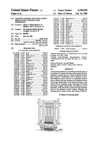
FIG. 17 is a detailed hardware block diagram ofthe
CNC controller illustrated in FIG, 16;
FIG. 18is a functional block diagram ofthe adaptive
and closed loop control of one axis of the tape laying
machine illustrated in FIG. 1;
FIG. 19 is a representative flow chart ofthe execu
tive routine used to regulate the processor of the con
troller illustrated in FIG. 17; and
FIG. 20 isa representative flow chart ofthe machine
language routines used for input and output ofdata to
the processor ofthe controller illustrated in FIG. 17.
DETALED DESCRIPTION OF THE
PREFERRED EMBODIMENT
General Orientation
The tape laying head 20 ofa composite tape laying
machine to which the invention is applied is illustrated
in FIG. 1. The tapelaying head 20 is shown suspended
from a gantry mounting, poised for laying a course of
tape from right to left upon the curved, upwardly-fac
ingsurface ofa mandrel22.The mountingarrangement
of the tape head 20 provides five axes of movement,
three linear in axes X, Y, and Z, and two rotational in
axes A and C. A-axis motion is rotational about a hori
zontal line parallel to the X-Y plane through the center
of the tape laying head 20 while C-axis motion is rota
tional about the Z-axis.
The gantry mounting comprises a pair of spaced
parallel rails 24 each elevated upon any suitable trestles
26orothersupportsand spanned by a cross rail carriage
28 which is driven along the parallel rails in a direction
perpendicular to the plane of FIG. 1 to provide what is
termed the X-axis movement of the tape head 20. The
X-axis drive is a gear and rack (not shown), the pinions
ofwhich are mounted at the ends ofcross shafts 30 and
31 suspended from the cross rail carriage 28 and driven
without backlash by a pair ofopposingservo motors 32
and 33 mounted on the underside of the cross rail car
riagemidway ofitsspan. Feedbackpositionsensors(not
shown) such as angular resolvers are provided with
respect to servo motors 32, 33 to generatesignals indic
ative oftheactual position ofthetape layingheadalong
the X-axis.
Lateral or Y-axis movement of the tape head 20 is
provided by a movable saddle 36 mounted on ways 38
on thefacingside ofthecross railasseen in FIG. 1.The
saddle 36 is driven along ways 38 by a pair ofopposed
20. 4,750,965
7
servo motors 40 and 41, each driving pinions (not
shown) engaged without backlash with the opposite
tooth flanks of an elongated rack 42 extending along
most ofthe span ofthe cross rail 28 and atop the lower
oneoftheways38. Angularresolversorotherfeedback 5
sensors are associated with servo motors 40, 41, togen
eratesignalsindicative ofthe actual position ofthetape
laying head along the Y-axis.
The tape head 20 is secured to the lower end of a
torque tube 44. The torque tube 44 and a ran 46 are
vertically slidable in the saddle 36, the torque tube 44
being rotated by servo motor 47 through a zero back
lash gear drive 48 to provide the rotational movement
of the tape head 20 about a vertical or C-axis. The ram
46 is also vertically movable within the saddle 36 by a
servomotor and ball screw drive 49 (not shown in de
tail) toprovide vertical orZ-axis movement ofthe tape
head 20. The actual position of the tape head 20 with
respect to the Z-axis and C-axis are derived from feed
back position sensors, such as resolvers or the like,
associated with servo motors 47 and 49.
The fifth axis of movement ofthe tape head, termed
A-axis rotational movement, is best appreciated by
comparing FIGS. 2,3and4, which illustratea two-part
frameofthe tapehead 20, includinga suspension frame
50 andasaddle-shaped frame 52 which carries the tape
handling mechanism. The suspension frame 50 com
prises a horizontal mounting plate 53 for securing the
frame to the torque tube 44 and a broad vertical face
-plate 54 braced to the mounting plate 53 by corner
“brackets 55 on the front side ofthe faceplate and plate
stiffeners 56 on the rear. On its front side, the faceplate
“54 carries a pair ofprecision ways 58 concentric upon
the A-axis ofthe machine. The A-axis is tangent to the
underside ofthesegmented tapelaydown roller60atits
axial centerwhen the rollerisin laying position,as later
explained. The A-axis is perpendicular to the plane of
"FIG. 2, and projects as a point in that plane.
* The saddle-shaped frame 52 of the tape laying head
20 includes a turntable 62 mounted on the precision 40
ways 58 ofthe suspension frame 50. The turntable 62 is
rotatedabout theA-axis bya servo motorand gearbox
64 mounted on the faceplate 54 which drives two pin
ions (not shown) engaged with zero backlash with the
opposed flanks ofa rack 68 secured on the mating face
oftheturntable62 (FIGS. 3 and 4). Theprecision ways
58 on thesuspension frame 50preferablyprovide 30' of
A-axis movement either side of center, and the rota
tional drive ofthe torque tube 44 in the ram 46 of the
machine is designed for C-axis rotational movement of 50
190" in either direction of rotation from a zero refer
ence. A feedback position sensor such as a resolver or
the like associated with the servo motor 64 provides a
signal representative of the actual positions ofthe tape
head 20 with respect to the A-axis.
Thereisan internal coordinatesystem forpositioning
the tape head 20 which is based on the center point of
the laydown roller 60. The origin for the internal coor
dinate system is floating or moveable so that the ma
chine maybe used easily with many different size man
drels with precision. The signals from the feedback
position sensors for the X, Y, Z, A, and C axes are used
to locate the position in space ofthe center ofthe tape
laydown roller60. Bymatchingthesepositionswith the
preprogrammed positions from a controller unit 35
(FIG. 1), the tape head 20 can be moved to lay tape
courses on the mandrel surface and build plies of the
courses into laminated articles.
O
15
20
25
30
35
55
65
8
The Tape Head Proper
Thepreviously mentionedsaddleframe52 ofthe tape
head proper comprises a pair ofspaced plates 63 each
respectively secured to the saddle shaped frame 52. A
tapesupply reel 70 mountedbetween the plates 63 at the
upper forward end ofthe frame, i.e., at the upper right
in FIG. 3, carries a supply of the composite tape 72
adhered to a releasable backing paper 74 which sepa
rates the coils of composite tape on the supply reel.
From the supply reel 70, the tape 72 and backing paper
74 pass around an idler roller 76 with paper side in
contact with the roller, from which it proceeds in a
straight line down to the laydown roller 69 at the very
bottom ofthe tape head. A guide roller 67 removes any
curl from the tape between the idler roller 76 and lay
down roller 60 before it enters feedback sensor 140. The
adaptive feedback sensor 140 generates a signal which
indicates whether the tape 72-74 is centered on the
laydown roller 60. The laydown roller 60, moving from
leftto rightin FIG. 3, applies pressure to the composite
tape to adhere it to the underlying lay surface of the
mandrel 22 and to ensure it lies flat.
As the tape head 20 is moved along a path or track, a
tapecourse is laid on the surfaceand the paperbacking
tape 74 is simultaneously peeled or released from the
composite tape 72 as the latter is laid. The paper back
ing tape 74 then proceeds diagonally upwardly, being
trained in an S-shaped path about a pinch roller 78 and
a driven roller80, and thence to a papertake-up reel 82
atthebackend ofthe tape head 20. A guide roller71 is
used to remove the curl from the backing paperbefore
entering the tape up reel 82and guidance sensors 73. A
photoelectric feedback sensor 73 in combination with a
similarsensor forthesupply reel generatesignals which
ensure that when a course oftape is started, it always is
initiated on the edge ofthe rollers no matter where the
last course ended.
The tape supply reel 70 and the paper take-up reel 82
are each respectively driven by timing belts from sepa
rate torque motors 84 and 86, respectively, and are
regulated to maintain a predetermined level of tension
on the paper backing tape 74. Both reels are provided
with spring-biased follower arms88 and90 which sense
the changing radius ofthe tape on each reel to adjust
their respective torque motors to maintain the preset
tension.
The composite tape 72-74 is drawn from the supply
reel 70 at times merely by the advancing movement of
the tape head 20 over the lay surface after the leading
end of the tape is anchored to the lay surface, but is
additionally positively driven at the beginning and at
the end ofeach tape course, i.e., before sufficient adhe
sion is developed between the composite tape 72 and
the lay surface to anchor the tape to the lay surface as
the tape laying head movesaway, and is also positively
driven near the end ofthe tape course when the adhe
sion ofthe composite tape 72 to its paper backing tape
74 may be insufficient to prevent separation ofthe pre
cutend ofthecompositetapefrom itsbacking.Thetape
is also positively driven to reposition and realign the
tape within the tape head 20 between the end of one
course and the start of the next course, i.e., when the
laydown roller 60 is not in contact with the mandrel.
The Tape Drive
The tape drive comprises the two aforementioned
rollers 78 and 80 about which the paper backing tape
21. 4,750,965
makes the S-turn enroute to the take-up reel 82. The
upper one ofthese rollers, roller 80, is driven by a re
versible servo motor 81 seen on the left side elevation
(FIG. 4) mounted on the outside ofthe saddle frame 52
ofthe tape head and driving thedrive roller80through 5
a right-angle gear box. The lower roller, 78, which
functions as a pinch roller, is mounted on a rocker arm
79 (FIG. 3), the opposite end ofwhich is connected to
a double-acting, short stroke air cylinder 92 which is
energized either to open or close the nip between the 10
two rollers.
Whenitisdesiredto drive thetape ineitherdirection,
the aircylinder92is energized to close the nipbetween
the rollers 78 and 80, and the servo motor 81 is ener
gizedin theappropriatedirection, unloading one or the 15
otherofthetorquemotors84and86servingthetake-up
reel 82 and the supply reel 70, causing one to play out
tape and the other to reel it in. The same arrangement,
i.e., with the nip of the two rollers closed, similarly
servesasabrake which isset whenever thetapehead is
lifted out ofcontact with the lay surface.
When the aircylinder92 is energized to open the nip
between the two rollers for the intermediate portion of
the tape course, the releasable backing paper remains
entrained in its reverse bend about the two rollers. 25
When the tape is moving relative to the tape head 2 by
means other than the drive motor 80, as during the
laying ofa tape course, then the wrap of the backing
tapearound the drive roller 80 generatessufficientfric
tion to drive a resolver attached to the motor to record 30
the amount of tape laid by measuring the number of
turns of the drive motor 81, whether or not the drive
motor is energized to draw tape from the supply reel.
The Laydown Roller Subassembly 35
The laydown roller 60 is part ofa roller subassembly
94 best seen in FIGS. 5-9, 12, and 13. The subassembly
94 includes a pair ofparallel plates 96 which are con
nected together in spaced relation by four posts 98 and
secured to the underside ofthe spaced plates 63 ofthe 40
saddle frame 52 by angle brackets 100.
Secured to the underside ofthe subframe 94 is a pair
ofmounting blocks 102 spanned by a support shaft 104
for the laydown roller 60. Comparing FIGS. 5 and 7, it
will beseen that the support shaft 104 issquarein cross
section and that each ofthe 12segmentsor rollers ofthe
laydown roller 60 comprises a disk-like central hub 106
having a vertical slot 108 to receive the support shaft
104in slidingfit. A pin 110extends longitudinallyalong
theslotin thehub 106andpasses throughacorrespond- 50
ing hole in the support shaft 104 to maintain the hub in
floating relation with the support shaft but positioned
axially thereof.Acompressionspring112surrounds the
pin 110 and biases the roller hub to a fully retracted
position on thesupportshaft 104when the tape head 20 55
is lifted from the lay surface. The rotatable portion of
eachsegmentoflaydown roller60isconfined totherim
114 which is separated from the hub 106 by ball bear
ings 116.
Bearing downwardly upon the rim 114 ofeach seg
ment ofthe laydown roller 60 isa roller 117 ofa rocker
arm 118,alternaterockerarmsbeingjournaledonshafts
119, 121 onoppositesidesofthe rollersubframe94,and
each being urged against the tops of the rims of the
rollersegments 60bya doubleair cylinder 120. Each air 65
cylinder 120 has its lower piston rod 122 connected by
means of a clevis to an associated rocker arm 118 and
has its upper piston rod 124 received in the frame ofa
20
45
10
load cell 126 secured to a mounting block 128 pivoted
on a shaft 130 spanning the sideplates ofthe subassem
bly frame.
One ofthe two cylindersshown in FIG. 7is shown in
diagrammatic cross-section to facilitate the description
ofits structureandits function, but the actual air lines to
the cylinders are omitted for clarityandareshown only
diagrammatically in connection with the sectioned cyl
inder. The air cylinders 120 maintain a predetermined
level of pressure on the rocker arms and hence the
rollersfor thelayingofthe tape. Theneutral position of
thesegments oflaydown roller 60 relative totheircom
mon supportshaft 104is the position depicted in FIG. 7
where the rockerarms 118 are urged downwardly upon
the segments ofthe roller 60 by pressurizing the upper
piston 121 of cylinder 120 on its underside, which is
vented above, and by pressurizing the lower piston 123
from above, which is vented below, through asolenoid
valve 132.
The normal laying position ofthe rollers 60 is main
tainedas necessaryby theadaptive control oftheA and
Z-axes still to be described. In that predetermined posi
tion, the piston 123 of the lower cylinder is spaced
approximately 0.020 inches from the top of the lower
cylinder so that when the laydown roller starts or fin
ishes a course oftape which has been cut atan angle to
the axis ofthe tape, the predetermined laying pressure
canbeappliedor removedsequentiallyfromsegmentto
segment ofthe laydown roller 60. This is important at
the conclusion ofeach such tape course, because, ifthe
laydown pressure were applied uniformly across the
breadth ofthe tape during the conclusion ofa course,
the leading end of the next course of tape would addi
tionally adhere to the lay surface. A selective applica
tion ofpressure is effected by reversing the application
ofair pressure to the lowerpiston 123 through the valve
132 in FIG. 7, i.e., pressurizing the lower piston 123 of
the cylinder from below while venting it above, thus
lifting the associated rocker arm 118 by the amount of
the head space above the lower piston 123.
In all other circumstances, i.e., in laying the tape
throughout the mid-portion ofthe tape course, the pre
set laydown pressure is maintained as earlier described
with the piston 123 of the lower cylinder extending
itself to maintain pressure when its associated roller
segment encountersa depression and one orboth cylin
ders retracting as necessary to accommodate any local
hump or rise in the contour of the lay surface. The
transducers 126do notenterin thecontrol arrangement
as such, butare used to providea record ofthe individ
ual laying pressures to an off-site recording instrument.
When in the neutral position, asshown in FIG. 7, the
laydown roller 60 exerts a substantially constant pres
sure on the composite tape72 to adhere the tape to the
underlyingsurface 22. Theforce ofthe rockerarms 118
on the individual segments or rollers is partially bal
anced by the force of the tape resisting this pressure
along with the springs 112. Only when the mandrel
surface 22 is identical to where the tape head is pro
grammed to be, isthere the correctbalance and, hence,
correctlayingconditionson thetape. Ifthesurface22is
lower than expected, then the ram 46 must be extended
to maintain contact with the surface and to ensure a
constant tape length between the tape sensor and the
laydown roller. Further, if the tape head tilt does not
match theslope ofthe contouron which the tape is laid,
then the roller segments will not be parallel with the
supply reel, rewind reel, idler roller, and pinch rollers.
22. 4,750,965
11
This will cause the composite tape to wander from the
centerline ofthe head and is undesirable. To ensurethat
the correct laying conditions are maintained, a number
of sensors for the A, C, and Z-axes are used to sense.
abnormal tape laying conditions.
Adaptive Sensors For A and Z Axes
Comparing FIGS. 7and9, itwillbeseen thateach of
the rocker arms 118, for the roller segments numbered
1, 4, 9, and 12, is provided with an arm 133 extending
rearwardly from the rocker shafts 119, 121 upon which
the rocker arms are journaled, and that each of the
rearwardly directed arms 133 extends into the interior
space of photodetectors 134, each having a C-shaped
frame, so as to interrupt the light beam thereof. The
neutral position for thearms 133 within photodetectors
134 is better seen in FIG. 13. In addition thereto, the
rockerarm bearinguponlaydown rollersegmentNo. 6,
flanking the central plane of the laydown roller 60, is
provided with an upstanding arm 136 which similarly
extendsinto the C-shaped frame ofa photodetector 138
to interrupt partially the light beam thereof.
Collectively, the photodetectors 134and 138provide
a means of ascertaining whether the roller segments
bearing upon the tape at its edges, and the segment
adjacent the central plane ofthe roller gang, are in the
neutral ordesired laying position ofFIG. 7. Ifeither of
the roller segments Nos. 1 and 12, when laying 6-inch
tape, or roller segments Nos. 4 or9 when laying 3-inch
tape, isindividually disposed either up or down so as to
asdisturb the balance of the signals generated by their
respective photodetectors 134, the imbalance is used to
energize the A-axis position control in one direction or
at theothertochangethetiltofthetapehead20to restore
- that balance. If, on the other hand, the centrally-located
roller segment No. 6 should change its elevation rela
tive to the mounting shaft 104, its associated photode
tector 138signals theZ-axisposition control forcorrec
tive action to raise or lower the roller segment No. 6
s: until the neutral signal value is restored. In each case,
: corrective energization of the appropriate servomotor
is isaccomplishedin combinationwith tapeheadposition
i.ing through position control circuitry, hereinafter de
scribed, for a particular axis.
FIGS. 14and 15 illustratean exaggerated tapelaying
condition where the A-axis and Z-axis require correc
tion. In FIG. 14, itisseenthat themounting shaft 104 is
lowerthan the neutral position which is indicative that
it is not parallel to mandrel 22, i.e., the actual surface is
higher than the representative surface. The length of
thetapebetween thetapesensorand the laydown roller
60 is shorter than that designed for and mustbe length
ened to the neutral position. The tape laying head 20
should be moved upwardlyalong the Z-axis to achieve
the neutral balance position.
In addition, the mounting shaft is not equally posi
tioned with respectto all the segments ofroller 60.The
rim 114 ofthe roller on the left side of FIG. 14, which
is that pictured in FIG. 15, is lower than the roller on
the rightside ofthegang. This is caused by an incorrect
tilting ofthe tape laying head along the A-axis. As pic
tured, the tape laying head 20 is vertical in FIG. 14
ratherthanbeingtiltedslightlyto therightsuch thatthe
rollergangwill travel normal to theside ofthe contour.
Ifthelaydown roller 60is notparalleltothesupply reel,
rewind reel, idler roller, pinch rollers, etc., this will
cause the tape to wander from the center line of the
head which is undesirable.
O
15
20
25
30
35
40
45
50
55
60
65
12
Not part of the adaptive control but serving to pro
tect the mechanism in the event ofmalfunction or over
travel during manual control, the rockerarm 118 ofthe
No. 7rollersegmentisprovided with an upstandingleaf
139 which is poised for the sequential operation oftwo
microswitches 141 and 143shown in FIGS. 12, 13 in the
event the laydown roller 60 rises abnormally. The first
microswitch 141 encountered interrupts power to the
Z-axis servomotor and the second microswitch 143
interrupts power to the entire machine to provide an
overtravel protection system for the tape head 20.
Adaptive Sensor For C-Axis
As the tape head 20 moves along its preprogrammed
path during the laying ofa tape course, the position of
the composite tape72 relative to the axial center ofthe
laydown roller 60 is constantly monitored by a pair of
photodetectors 140 each ofwhich is adjusted to inter
ceptan edgeofthetape72insuch amannerasto render
signals ofequal value when the tape is centered on the
laydown roller 60. These photodetectors 140 are lo
cated (FIG.S. 3, 7, and 10) on each side ofthe tape path
so as to monitor the double-layered tape just before it
reaches the laydown roller 60. With this positioning, a
reasonably accurate reading ofthe amount ofthe side
ward drift, if any, of the center of the tape from the
center of the laydown roller 60 can be is monitored.
For thisservice, the photodetectors 140 are mounted
for equal adjustment toward and away from the central
plane of the laydown roller 60, and are adapted to in
crease or decrease the lateral distance between them to
compensate for variations in the tape width from its
nominal widths of3 and 6 inches. The equal distance of
the photodetectors 140 in opposite directions from the
central plane ofthe laydown rollerprovidesa balanced
signal when the tape is centered on the laydown roller
60, and the distance between the two photodetectors
140 relative to the width of the tape determines the
strength of the balanced signal received from the two
sensors when the tape is centered. Thus, as the center
line ofthe tapedriftsawayfrom thecentralplane ofthe
laydown roller 60, the signals received from the tape
edge photodetectors 140 become unbalanced, and their
imbalance is used to generate a command to the C-axis
positioning control to rotate the torque tube 44, and
thus the tape head 20, until the balance is restored, i.e.,
until thetapeis recentered beneath thelaydown rollers.
FIG. 13Aillustrates a representative output voltage asa
function ofthe area interrupted by the tape for each of
the photodetectors 134, 138, and 140.
FIGS. 10 and 11 illustrate in detail the assembly for
the C-axissensor 140. Theassembly comprisesa slidable
carriage 220 which may be positioned by a knob. 236
with respecttoastationarymountingplate63.Mounted
on the carriage 220 are a pair ofC-shaped photodetec
torblocks 226 and 228 which are slidably supported by
a ledge 246 and bolts 240 and 242, respectively which
are passed through an aperture in each block and re
tained in slots in the moveable carriage 220. The com
positetape 72, shown in phantom, rides along the guide
rollers 67 (FIG. 3) and passes through the channel
formedbythephotodetectorblocks226,228.Theedges
ofthe tape 72, if it is perfectly centered, will interfere
with lightbeing passedbetween photodetector 248 and
light emitting diode (LED) 250 and photodetector 252
and LED 254, respectively, at approximately 50% of
thetransmission capability. Ifthe voltagesoutputbythe
sensor pairs are not substantially equal to each other,
23. 4,750,965
13
then the edge of the tape has walked away from the
center line path, and the tape head 20 should be turned
in that direction to cause that edge to move back into
interference with the sensor path. Similarly, as one tape
edge walks away from one sensor, the opposite will
occur at the other sensor where its output will be less
than nominalastheedgecoversmoreofthesensorarea.
This provides a check on the tape position by the oppo
site sensor and generates a differential reading which
can be used to rebalance the tape position adaptively.
The assembly also provides a way of visually deter
mining whether the photodetector is exactly calibrated
and a facile method ofchanging the calibration between
different sizes of tape. Generally for the tape laying
apparatusillustrated,a 3inch ora 6inch compositetape
width is used. A position sensor probe 232 which
touches a calibration block 234 of the moveable car
riage 220 provides an indication ofthe relative position
of the slide assembly with respect to a fixed position
such as carrier plate 63. This relative positioning is
indicated visually on a dial indicator 230 to allow a
operator by turning knob 236 to obtain a calibration
reading on the dial and visuallyinspectdial 230periodi
cally to determine ifthe calibration is still valid.
The actual calibration ofthe sensor will now be more
fullydescribed with reference to FIGS.10, 11, 13A,and
13B. FIG. 13B shows the composite tape 72 covering
approximately halfofthearea ofthe photodetector226
which would produce a zero or balanced output volt
age from the function shown in FIG. 13A. Initially,
photodetectorblock226is mounted on theledge246of
slide assembly220and slid to whereitabutsa reference
wall 258 of slide assembly 220. The bolt 240 is then
tightenedtofixtheposition ofblock226with respectto
the slide assembly 220. Next the block 228 is mounted
on theledge246and alignedbyasetscrew 244. Theset
screw 244 is adjusted to move the block 228 toward
block 226. The set screw 244 is adjusted until the cen
ters ofthephotodetectorblocks226,228areexactlythe
nominal width ofthecompositetapeapart, inourexam
ple 6 inches. The bolt 242 is then tightened to fix the
sensor block 228 with respect to the slide assembly 220
and thesensorblock226. Afterthisinitial portion ofthe
calibration is completed, thephotodetector centers will
beexactly 6inchesapartand, therefore, need onlytobe
centered on the tape 72 (center of C-axis).
The knob. 236 adjusts the slide assembly 220 along
ledge 246 (FIG. 10) while the tape 72 is positioned
exactly along the center line of the tape path. This is
accomplished by taking a length of tape and manually
positioning it with respect to the center axis of the lay
down rollers 60 and the supply reel 70 such that it is
under normal tension and does notincludeany wrinkles
or curves in the path. The knob. 236 is then adjusted
while electrically sampling the outputs ofthe photode
tectorblocks226,228to obtainazerooutputfromeach.
The set screw 244 can be readjusted if a zero reading
cannot be obtained from each sensor. After the entire
assembly has been calibrated, the reading from dial
indicator 230 is recorded and that data stored as the
calibration constant. If the slide assembly has to be
moved, such as for repairs, cleaning, tool change over,
etc., the device can thereafter be rapidly calibrated by
adjusting the knob 236 to bring the slide assembly back
to the position which produces the original reading on
dial 230.
The same technique and ease of calibration is avail
able when changing to tapes ofa different width. It is
10
15
20
25
30
35
45
SO
55
65
14
known that the centers ofthe sensor blocks 226 and 228
are exactly 6 inches apart and are defined by the extent
ofthe set screw 244and reference wall 258. A pair of 1
inch blocks can be inserted between the wall 258 and
sensor block 226 and the set screw 244 and sensor block
228toprovide a calibration for changing the tape laying
machine over to a 3 inch tape. The calibration and set
tings will not have changed only the position of the
sensors blocks 226, 228 relative to the reference posi
tions. Byaccuratelyproviding theauxiliaryblocks with
the correct width, the sensor blocks 226 and 228 may be
moved exactly 1 inches along the ledge 246 to cor
rectly reposition them with respectto a 3 inch tape. The
bolts 240 and 242 are then tightened to secure them in
that position. Reversal ofthe method permits a change
from a 3 inch to a 6inchtape. Thus, notonlyhasafacile
method ofcalibrating the C-axis adaptive control with
respect to the pressure roller center been shown, but
also a rapid change between tape widths without the
necessity ofrecalibrationhas been advantageously illus
trated.
The Control Logic
As more fully seen in the block diagram of FIG. 16,
the motions ofthe tapelaying machineare regulated by
the control unit 35 (FIG. 1) including a controller 300
which produces electrical control signals and receives
position and adaptive feedback signals to position the
tape laying head 20 according to positions commanded
by a part program. The part program defines the de
siredposition inspaceofthetapelayinghead20and the
position feedback signals indicate the actual position of
the head to the controller 300. The adaptive feedback
signals indicate the relation ofthe actual surface to the
mathematically derived surface and the tape laying
conditions. Thedifferenceamong thesesignals is nulled
in a closed loop until the actual position equals the
desired position such thatthe tape tracks a natural path
and is laid in a precise manner. Signals indicating the
differencebetween theactual and desiredpositions may
be provided to a satellite quality control computer 342
to determine whether the tape is being laid correctly
and to store the results of the actual lay.
The controller 300 is a CNC machine which can
execute an extensive and detailed part program, a por
tion at a time, by being periodically supplied with se
quentially generated control blocks. These control
blocks contain detailed motion and control information
in each block and are comprised of series of standard
ized control function implementations for the particular
tape laying machine. Executing the control blocks
causes the actual physical motion and control of the
tape laying head 20 along a natural path.
In the present system the controller 300 is imple
mented as an Allen Bradley 8200 CNC controller, or
equivalent CNC controller, which can be programmed
to regulate motion and control ofa multi-axis tape lay
ing machine. The program ofthe controller 300 imple
ments a closed loop control which is given its desired
position commands by a control processor 344. These
position commands are executed by the controller 300
to position the tape head 20 in a normal closed loop
manner. These positions are modified for actual surface
conditions for the A, C, and Z-axes by the adaptive
feedback signals mentioned previously,
The adaptive control actively regulates the vertical
positioningofthe laydown roller60 (Z-axispositioning)
to maintain surface contact with a constant application
24. 4,750,965
15
pressure and a substantially constant tape length be
tween the cuttersand laydown roller,actively regulates
the A-axis positioning to maintain an equal length of
tapefrom side to side, and actively regulates the C-axis
positioning to maintain the tape squarely under the
rollers 60.
The control blocks ofmachine instructions aregener
ated to the controller 300 by a control or interpreter
processor 344. The control blocks are generated by the
interpreterprocessor344from part programs generated
by a part program generator 320 or previously gener
ated part programs stored inasystem storage unit306.
The part programs, comprising a plurality of tape
blocks, are in a geometric format relative to the natural
tape path of each course. The information for each
courseconsistsofone tapeblockdescribingtheendcuts
ofa course and one or more tape blocks describing the
course centerline of the path. This format contains all
thegeometric information forone course ofa ply butis
not machine specific.
Thecontroller300, however, only recognizes regular
machine instructions or commands representative of a
single machine action or canned cycle machine instruc
tion commandsindicatingapluralityofmachineactions
in a single block. The course tape blocks contain com
plex information which command many more machine
actions, such as axis motion, sheer and cutter control,
roller control, and other miscellaneous functions.
Therefore,thiscomplexcoursedatamustbeinterpreted
and converted into the machine instructions that the
controller 300 recognizes. This is the function of the
interpreter processor 344 which expands the tape
"course blocks into detailed motion and control blocks of
machine instructions recognizable by the controller
300.
The partprogram generator 320 accepts basicarticle
information from a surface file 336 and periphery data
from an APTpartprogram 328 to automatically gener
trate the tape courses based on a natural path which are
... outputasapartprogramfromapostprocessor326.The
iftape course information or part program from the post
processor326can be alternatively communicated to the
control processor 304 through any of the three inter
faces 314, 316, or 318. The part program may be inter
faced through a tape punched paper314by punch tape
308, output on magnetic tape310 from a tape drive316,
or interfaced directly through a telecommunications
interface 318 and a protocol converter 312.
Theinformationusedtogeneratethetape course data
from the surface file 336 and periphery data from APT
part program 328 is a rectangular array of points ob
tainedfrom a mathematical description ofthesurfaceof
the mandrel 22, the peripheral outline ofthe plies to be
laid, one or more control lines indicating areas where
the gaps between courses are to be held at a close toler
ance, and the angle at which the courses of each ply
should be laid with respect to the X-axis.
The program generator 320 receives this information
and usesa conventional APTprocessorprogram 330 to
assemble a basic part program shell. The program shell
consists ofgeometric information describing the article
to be manufactured by the number and position of the
plies and the general direction and configuration ofthe
tape courses. This shell is made from the surface infor
mation stored in data file 336 and from command data
previously stored asstandard APT part programs from
file328.The APTprocessor330isaprogramproviding
the necessary software tools for a part programmer to
O
15
20
25
30
35
45
50
55
60
65
16
assemble the part program shell from these two data
sources. The part program shell essentially describes
the article in the geometric terms ofplies but without
natural path data included.
Once theshell programis assembled from thevarious
sources of data, it can be expanded by a course and ply
generation routine 322 to include natural path data for
the tape courses. The courseand ply generation routine
322 may be commanded to generate a whole ply or to
generate individual courses with natural paths for the
control processor 344. When a command is given to
generate a ply, the system automatically computes all
the natural paths and end cuts foreach course covering
the area bounded by the ply periphery. The gaps be
tween the courses of the ply are kept at a specified
tolerancealongthecontrollinesand thedirection ofthe
tape lay can be reversed 180° between two adjacent
courses to minimize machine motion and tape scrap.
After the courses ofone ply are generated, the surface
data in memory are updated to reflect the thickness of
the new ply.
The part program generator 320 provides graphics
monitoring with a video monitor 334 where the gener
ated courses of the composite tape can be visually in
spected by an operator on a graphics display. With the
aid of the graphics monitor 331, a part programmer
through the keyboard ofthe monitor can make adjust
ments to the courses to provide more control over the
gap and overlaps ofthe tape courses for a ply.
FIG. 16Aillustratesa graphical representation ofthe
data which is input to the part program generator 320.
Theinitial orstartingsurface ofthe mandrel 22is math
ematically represented by surface 301 as a number of
rectangular coordinate points forming a grid. The grid
lines are equally spaced along the surface of the X-Y
plane 302 a real distance apart, such as one inch. The
grid pointsarestoredin thesequential datafile336such
that the X, Y, and Z coordinates ofeach surface point
are maintained foroperation by the partprogram gener
ation. For the preferred implementation, the maximum
size ofa grid is 600X 160 grid points.
Projected on the surface 301 is a ply periphery 304
which definestheoutermostedgesofthefinishedarticle
on the mandrel.Theplyperiphery304isprojectedfrom
the X, Y plane such that the same termination criteria
forthe courses maybeused for all the differentplies by
projection.Thesurface301describedbythegridpoints
is extended at least some distance beyond the edges of
the intended article because during natural tape path
calculation some of the edge points calculated may end
up outside ofthe edges ofthe part. To correctly calcu
late these points, the surface extension is necessary.
Acontrol line305isalsoprovided fordeterminingan
area along which the gaps between courses oftape are
closely controlled. The control line 305 is further de
fined in the X, Y plane such that it may be projected
upon each ply similar to the manner that the periphery
304 was projected. One ply of composite tape laid on
thesurface301 is shown, asis the projection304" ofthe
plyperipheryonto theZcoordinates ofthesurface301.
The control line projection 305 from the control line
305 is also shown.
Each course, for example 307, 309, 311, follows a
natural path on the surface or contour 301 without
putting unequal tension on the edges of the course and
has its ends cut to fit within the periphery. Each course
is laid on the surface in an opposite direction to the one
adjacent to it to minimize tape waste and machine mo
25. 4,750,965
17
tion. The gaps between adjacent courses, for example,
313 between courses 307 and 309, and 315 between
courses 309 and 311 are controlled to a very close toler
ance along control line projection 305 but are not as
closely regulated away from that line. General angles
thatthe tapecoursesmakewith respecttotheX-axisare
0', 45, and 90'. Further, particularly for the 45" appli
cation, plies may alternate from 45 to -45 so that
the courses ofadjacent plies will crisscross for strength
in thebuilding ofan article. However, it is readily evi
dent that any angle with respect to a reference may be
used.
The computation of the natural path is basically as
follows. First, a load point 321 is calculated on the
surface where the natural path on the surface 301 will
cross theprojected control line305'. The course path is
now split into two paths, with each path starting at
point321 and being computed in opposite directions at
a control angle until they intercept the opposite ply
peripherysegments323,325.The computedpath points
are then merged into one path and rearranged to havea
pathdirection oppositetothatoftheanadjacentcourse.
The initial courseangle is measured with respect to the
X-axis at the point where the center of the course
crosses the control line.
There are several distinct advantages to this method
of calculating a natural tape path on a complex con
toured surface. Initially the gap distance 313, 315 be
tween tape courses on the control line can be readily
regulated because the load points are picked along it.
Further, the natural path is generated in both directions
from the control line such that, although the gaps are
not tightly controlled, the tension in the edges of the
tape are minimized. This prevents wrinkling, overlays,
and other detrimental positionings of the tape. More
over, the angular orientation tape courses with respect
to the control line allow a efficient use ofthe tape while
minimizing the complexity of the end cuts. It is desir
able to lay the composite tape at an angle transverse to
the control line such that strength is maintained in the
compositearticlebutefficient useofthetape productis
also provided.
A hardware block diagram ofthe controller 300 and
itsinputs and outputs will now be more fully described
with reference to FIG. 17 to provide a better under
standing ofthe implementation oftheadaptive control.
It is seen that the controller 300 comprises a group of
inputcircuitry under thecontrol ofaninputcontrol 482
and a group of output circuitry under control of an
outputcontrol486. Controller300, as described herein
before, is preferably a CNC device including a main
processor 504 which communicates via a data bus, ad
dress bus, and control bus, collectively 505, to a digital
memory 484, the input control 482, and output control
486.Theoutputcontrol486developscontrolsignalsfor
a group of servos 494, 496, 498, 500, and 502 which
actually powertheservo motorsfor the A, C, X, Y, and
Z-axes, respectively, to cause coordinated movement
along the multiple axes by the tape laying head 20. The
input control 482 is used to control a digital port 506
through which the processor 504 communicates with
thecontrolprocessor304. Amachineinstruction is read
from the digital port 506 into the memory 484 for pro
cessing by the processor 504. The machine instruction
from the processor includes the data necessary for gen
erating the X, Y, Z, A and C-axis position commands
(508-516).
5
10
15
20
25
30
35
45
50
55
60
65
18
Further the input control 482 controls an input multi
plexer478 and an analog to digital converter 480. Dur
ing an input scan routine the multiplexer inputs are
sequentially scannedand the values obtained converted
to digital numbers which are stored in the memory 484.
The input ports to the input multiplexer 478 are con
nected to individual amplifier and conditioning circuits
476. The inputs to the amplifier and conditioning cir
cuitry 476 are from the adaptive sensors 452, 454, 456,
458, 460, 462, and 464 and position feedback sensors
466,468, 470, 472, and 474 ofthe tape laying machine.
TheZ-axisadaptivephotodetectorsensorisrepresented
at 452, while the A-axis adaptive photodetector sensors
for the 3 inch wide tape are shown at 454 and 456,
respectively. The6inch adaptivephotodetectorsensors
for the A-axis of the machine are labelled 458 and 460,
respectively. The two C-axis adaptive photodetector
sensors are 462 and 464, respectively. The feedback
position sensorsfor each ofthe fiveaxes Z, Y, X, C,and
A are shown as blocks 466-474, respectively.
The output controller486controlsa digital to analog
converter488 and an output multiplexer 490. The con
trol processor 504 receives the digital position com
mands from port 506 and the feedback signals from
A/D converter 480, and transforms them through a
plurality ofcontrol law loops into separate digital con
trol signals which command the motion of the tape
layinghead20.Thedigital controlsignals are outputby
means of the output control 486 to the D/A converter
488 where they are converted to analog control signals.
The output multiplexer 490 receives the analog control
signals for the X, Y, Z, A and C-axes from the digital to
analog converter 488 and applies them to the separate
servos 494-502 controlling the servomotor ofeach axis.
Morefullyillustrated in FIG. 18 is a block diagram of
a representative position control for one axis ofthe tape
laying machine having adaptive feedback. As such it is
representative ofeach oftheaxes A, C, and Z which in
thepreferredembodimentarecontrolledadaptivelyasa
superposition upon the part program natural path con
trol. However,itis evidentthat different types ofadapt
ive controllers could be used to regulate one or more
axes. The figure will be described with respect to the
Z-axis but it should be understood that the description
will apply equivalently to the other adaptive axes. The
X and Y-axes are controlled bysimilar position controls
without adaptive feedback.
The control ofeach tapeaxismovementisperformed
by a servo drive which generates a voltage or control
signal Vm to a motor420 which is connected to the tape
axis mechanics 422 for the particular axis. The servo
drive controls the motor 420 to position the tape axis
mechanics to a particular position or coordinate with
respect to a zero reference for the axis. A feedback
position sensor 424 measures the actual or absolute
position ofthe tape axis mechanics with respect to the
referencefor thataxis. Theadaptive position sensor426
for that axis measures the actual surface ofthe mandrel
22 and relates that surface to where the controller be
lieves the surface to be because of the mathematical
description used to derive the part program.
The servo drive is driven by a computerized numeri
cal control (CNC) software loop forminga control law
including a summing junction 408 and a control law
function generator410.The control law functioncanbe
any combination ofproportional, integral, and deriva
tive gains. The summingjunction 408 ofthe numerical
control software loop produces a velocity error signal
26. 4,750,965
19
based on the difference between a commanded or de
sired position and the actual position. The actual posi
tion is determined for the axis of the tape laying ma
chine in part by the position feedback signal from the
position sensor 424. With the position feedback signal,
the adaptive feedback signal from an adaptive sensor
426 is combined in the summing junction 408. The
adaptive sensor 426 generates the adaptive feedback
signal to form in addition with the position feedback
signal an actual position signal that relates the internal
coordinate system ofthe tape axis mechanics 422 to the
actual surface of the mandrel 22.
Generally, the difference between the commanded
position signal and theposition feedbacksignalgenerate
substantially the entire velocity error signal. However,
for those positions on the surface ofmandrel 22 which
do not conform to the mathematical description from
which the commanded position signal was generated, a
slight alteration from the adaptive feedback signal is
used to change the position feedback signal from the
internal coordinate system to that ofthe actual surface
of the mandrel 22.
The commanded or desired position signal is gener
ated at specific times from the control processor 304.
The control processor 304 takes a natural path part
program and does a machine specific translation as
illustrated by functional block 406 to determine the
movementsorcommandedpositionsforeachaxisofthe
tape laying head 20. The machine specific motion com
smand istheninterpolatedintoan axisposition command
in controller 300 before being input to the software
control loop at summingjunction 408.
- The servo drive of the controller 300 is of a type
...conventionally known in the art. The servo drive com
prises a standard velocity servo including a summing
junction 412, a proportional gainamplifier414,an SCR
...control 416, and tachometer 418. The feedback for the
servo drive, rather than being a position signal, is a
velocity signal from the tachometer 418 measuring the
10
15
20
25
30
35
speed ofmotor420. The summation injunction 412 of 40
the feedback and output of function generator 410
...causes a velocity error signal from the summingjunc
tion 412 which is proportional to the velocity of the
motor. Thus, theservo drive movesfrom pointto point
at a velocity determined by the commanded velocity
inputfrom function generator410signal whichisampli
fied byamplifier 414 and input to the SCRcontrol 416.
The commanded variations in motor speed are conven
tionallycontrolledbytheSCRcontrol 416which varies
the amount ofphase ofa AC waveform which is input
to the motor 420 every cycle. Such SCR controls are
standardly known to include one or more phases de
pending upon the windings and desired configuration
for motor 420.
The main control processor 504 is software con
trolled by a program shown generally in FIGS. 19 and
20. The input and output controls 482 and 486 are ser
viced on an interrupt basis by the routine of FIG. 20.
The machine language routine first operates an input
scanner subroutine 448 to read and store the input val
ues ofthe sensors 452-474. The routine will then call an
output scannersubroutine 450 to output the digital con
trol signals from the memory 484 to servos 494-502.
The machine language routine after it finishes the input
and output scanning, returns control to the place in the
main or executive routine ofFIG. 19 from which it was
called. Normally, the program is called or executed on
a real time basis every 10 millisecs such that the control
45
50
55
65
signals can be updated that quickly and the control
moves smoothly from point to point. All the feedback
position sensors arescanned every interrupt or 10 milli
secs while the adaptive sensors are scanned every 40
millisecs so that theycan be combined with the position
feedback signals.
The executive routine which operates in background
and acts as a main control receives position instructions
from theprocessorcontroller304and interpolates them
by function block 445 into the various commanded
positions for the tape laying head 20. The interpolator
445 determines how fast to change each commanded
position for each axis such that a linear path is taken
from one commanded point to another considering the
topography between them. Thus, the interpolator 445
will break up a command to move from position A to
position Binto a numberofposition commandsforeach
axissuch that the movementofthe tapehead20 iscoor
dinated between all axes. Thecommanded positions are
input periodically into separate software servo loops
444, . . . 446 for each axis where the individual control
laws act on them. The control laws operate on the posi
tion commandsand feedbacksignals to form the control
signals which are then stored in memory 484 and later
output to the velocity servos 494-502.
From the structure in FIGS. 17-20 it is evident that
the machine is controlled by a linear interpolative feed
back control to producea trackpath based on the natu
ral path algorithm. All the axes X, Y, Z, A, and C are
integrated onto thattrackingpath by use oftheinterpo
lator 445 illustrated in FIG. 19. The interpolator causes
the tracking path to be traveled in a linear manner be
tween points determined by the instruction commands
from the machine specific translation in block406. This
operation causesa coordination ordependence between
the axes for the accurately following the tracking path.
The adaptive feedback signals from the adaptive sen
sors, represented at 426, are added after this interpola
tion.
Becausetheadaptivefeedbacksignalsareaddedafter
the interpolative effects ofthe natural path control, the
signals do not specifically affect the tracking path as
there is no adaptive feedback on the X, Y-axes and the
adaptive signals are not interpolated themselves. The
adaptive feedback sensors are only added indepen
dently to those axes which affect the tape laying condi
tions. Thus, the adaptivesensor for the Z-axis indepen
dently adjusts the general tape laying head position on
the roller segments 60while theA-axis sensors indepen
dently adjust the tilt or A-axis position ofthe head 20.
Further, the C-axisadaptivesensors independently con
trol the rotation of the tape laying head 20 about the
C-axis such that the roller segments 60 are positioned
squarely in contact with the composite tape 72.
Because each adaptive feedback axis is independent
ofany ofthe others and all those axes have a path track
which has been previously interpolated, the adaptive
sensor signals do not affect the tracking path to any
degree. The adaptive sensorsignals provide slight alter
ations in the A, C, and Z-axis movements to bring the
tape laying head 20back to the neutral position or opti
mum tape laying conditions. The adaptive feedback
combines with the position feedback to translate the
actual surface to the position where the tape laying
machine believes the surface to be. With such control
the tape laying machine can reproduce parts with facil
ity even on lay surfaces which are substantially different
from that used to generate the natural path part pro
27. 4,750,965
21
grams, and produce substantially identical parts there
from with high production rates and precision toler
aCS.
While a preferred embodiment of the invention has
been illustrated, it will be obvious to those skilled in the
artthat various modificationsand changes maybe made
thereto without departing from the spirit and scope of
the invention as defined in the appended claims.
What is claimed is:
1. A multi-axis tape laying machine for depositing
composite tape on a lay surface in courses to produce
theplies ofa laminatedstructureofcompound contour,
said tape laying machine comprising:
a tape laying head moveable along a plurality ofaxes
in accordance with control signals from a control
processor means;
a mandrel having an actual contoured lay surface for
defining the shape ofat least one contoured ply of
said laminated structure;
said control processor means generating said control
signals in accordance with the natural tape path of
each course ofa ply along a representation ofsaid
actual surface; and
adaptive control means for independently modifying
said control signalstoat least oneindividual axisin
order to compensate for differences between said
actual surface and said representation ofthe actual
surface.
2. A multi-axis tape laying machine as defined in
claim 1 whereinsaidtape laying headis moveablealong
a vertical axis in accordance with said control signals
and includes:
a plurality ofpressdown rollersforapplyingaprede
termined amount ofpressure against said compos
ite tape, for maintaining contact with said surface,
and for maintaining a substantially constant tape
length between said rollers and a reference during
thedeposition ofthecourses,said contactand con
stant tape length corresponding to a specific roller
position with respect to a reference; and
said adaptive control means including means for ad
justing said roller position by movement of said
tape head along said vertical axis to maintain said
contact and constant tape length.
3. A multi-axis tape laying machine as defined in
claim 2 wherein said tape laying head is rotatable about
a vertical axis in accordance with said control signals
and includes:
guide means for providinga tapepath over the center
ofsaid press down rollers; and
said adaptive control means including means for ad
justing said tape head position by rotation about
said vertical axis to maintain said press down rol
iers centered on said composite tape.
4. A multi-axis tape laying machine as defined in
claim 1 wherein said tapehead is rotatableabouta hori
Zontal axis in accordance with said control signals and
includes:
a plurality ofpressdown rollersina row forapplying
a predetermined amount of pressure against said
composite tape during the deposition of the
courses; and
said adaptive control means including means for ad
justing the positions of said rollers by rotational
movement of said tape head about said horizontal
axis to maintainsaid rollerssubstantially parallel to
the actual surface.
10
15
20
25
30
35
40
45
50
55
60
65
22
5. In a multi-axis tape laying machine for depositing
composite tape in courses to produce the plies of a
laminated structure ofcompound contour wherein said
tape laying machine includes a tape laying head move
able abouta plurality ofaxes in accordance with control
signals from a control processor means, a mandrel hav
ing anactual contoured surface fordefining theshape of
at least one contoured ply of said laminated structure,
and said control processor means receiving machine
instructions forgeneratingsaid control signalsin accor
dance with the natural tape path ofeach course ofaply
along a representation of said actual surface, an im
provement comprising an adaptive control including:
means for sensing the variances between said actual
surface and said representative surface; and
means for independently changing said control sig
nalsaffecting individual axesto compensate forthe
variances between said actual surface and said rep
resentative surface without varying the natural
tape path ofeach course as it is deposited on said
actual surface.
6. An adaptive control asset forth in claim 5 wherein
said means for hanging include:
means for maintaining said tape laying head squarely
on the path ofsaid composite tape as it is laid by
said tape laying head.
7. An adaptive control as set forth in claim 5 wherein
said means for changing include:
means for maintaining said tape laying head substan
tiallyparallel to said actual surfaceassaid compos
ite tape is laid by the head.
8. An adaptive control as set forth in claim 5 wherein
said means for changing include:
means for maintaining said tape laying head in
contact with said composite tape and a substan
tially constant length of tape between a reference
and said surface as said tape is laid by said tape
laying head.
9.Theadaptivecontrolassetforth inclaim 5wherein
said means for changing include:
means for maintaining said tape laying head squarely
on the path ofsaid composite tape as it is laid by
said tape laying head;
means for maintaining said tape laying head substan
tially parallel to the actual surface as said compos
ite tape is laid by the head; and
means for maintaining said tape laying head in
contact and a substantially constant length oftape
between a reference and said surface as said tape is
laid by said tape laying head.
10. An adaptive control as set forth in claim 5
wherein said means for changing include:
meansforindependently adjusting theposition ofsaid
tape laying head along said individual axes to main
tain a neutral tape laying position with respect to
said actual surface.
11. An adaptive control as set forth in claim 10
wherein said means for sensing include:
meansforsensingthe neutralpositionsalongsaidaxes
ofsaid tape laying head with respect to said actual
surface.
12. An adaptive control as set forth in claim 11
wherein said position sensing means include:
means for sensing a neutral position for the tape lay
ing head along a vertical axis.
13. An adaptive control as set forth in claim 11
wherein said position sensing means include:
28. 4,750,965
23 24
15. An adaptive control as set forth in claim 11
wherein said position sensing means include:
tape laying head about a horizontal axis. means for sensing a neutral position for the tape lay
ing head along a vertical axis;
5 means for sensing a neutral rotational position for the
wherein said position sensing means include: tape laying head about a horizontal axis; and
means for sensing a neutral rotational position for the
tape laying head about a vertical axis.
k s :
means for sensing a neutral rotational position for the
14. An adaptive control as set forth in claim 11
means for sensinga neutral rotational position for the
tape laying head about a vertical axis.
O
15
20
25
30
35
45
50
55
65
29. UNITED STATES PATENT AND TRADEMARK OFFICE
CERTIFICATE OF CORRECTION
PATENT NO. : 4,750, 965
DATED June 14, 1988
INVENTOR(S) : Pippel et al.
It is certified that error appears in the above-identified patentand thatsaid Letters Patent is hereby
Corrected as shown below:
IN THE SPECIFICATION
Column 8, line l4, change "69" to --60--.
Column 8, line 33, change "tape up" to --take-up--.
Column 9, line 26, change "2" to --20--.
Column l0, line 20, change "rollers" to --roller--.
Column l2, line 27, after "be" delete "is".
Column l3, line 2l, change "a" to --an--.
Column l3, line 52, change "rollers" to --roller--.
Column l4, line 8, after "changed" insert a comma.
Column l7, line 22, delete "an" before "adjacent".
Column l7, line 37, change "a" to --an--.
Column l9, line 50, change "a" to --an--.
Column 20, line 36, after "for" delete "the".
Signed and Sealed this
Sixth Day ofJune, 1989
Attest:
DONALD J. QUIGG
Attesting Officer Commissioner of Patents and Trademarks