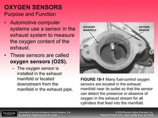
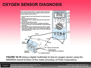
Automotive Fuel and Emissions Control Systems, 2/e
By James D. Halderman and Jim Linder
© 2009 Pearson Higher Education, Inc.
Pearson Prentice Hall - Upper Saddle River, NJ 07458
OBJECTIVES
After studying Chapter 18, the reader will be able to:
1. Prepare for ASE Engine Performance (A8)
certification test content area “E” (Computerized
Engine Controls Diagnosis and Repair).
2. Discuss how O2S sensors work.
3. List the methods that can be used to test O2S
sensors.
4. Describe the symptoms of a failed O2S sensor.
5. List how the operation of the O2S sensor affects
vehicle operation.
Automotive Fuel and Emissions Control Systems, 2/e
By James D. Halderman and Jim Linder
© 2009 Pearson Higher Education, Inc.
Pearson Prentice Hall - Upper Saddle River, NJ 07458
OXYGEN SENSORS
Purpose and Function
• Automotive computer
systems use a sensor in the
exhaust system to measure
the oxygen content of the
exhaust.
• These sensors are called
oxygen sensors (O2S).
– The oxygen sensor is
installed in the exhaust
manifold or located
downstream from the
manifold in the exhaust pipe.
FIGURE 18-1 Many fuel-control oxygen
sensors are located in the exhaust
manifold near its outlet so that the sensor
can detect the presence or absence of
oxygen in the exhaust stream for all
cylinders that feed into the manifold.
Automotive Fuel and Emissions Control Systems, 2/e
By James D. Halderman and Jim Linder
© 2009 Pearson Higher Education, Inc.
Pearson Prentice Hall - Upper Saddle River, NJ 07458
OXYGEN SENSORS
Construction and Operation
• The inner and outer
surfaces of the thimble are
plated with platinum.
• The inner surface becomes
a negative electrode; the
outer surface is a positive
electrode.
• Negatively charged oxygen
ions are drawn to the
thimble where they collect
on both the inner and outer
surfaces. FIGURE 18-2 A cross-sectional view
of a typical zirconia oxygen sensor.
Automotive Fuel and Emissions Control Systems, 2/e
By James D. Halderman and Jim Linder
© 2009 Pearson Higher Education, Inc.
Pearson Prentice Hall - Upper Saddle River, NJ 07458
OXYGEN SENSORS
Construction and Operation
FIGURE 18-3 A difference in
oxygen content between the
atmosphere and the exhaust
gases enables an O2S sensor to
generate voltage.
Automotive Fuel and Emissions Control Systems, 2/e
By James D. Halderman and Jim Linder
© 2009 Pearson Higher Education, Inc.
Pearson Prentice Hall - Upper Saddle River, NJ 07458
OXYGEN SENSORS
Construction and Operation
• There are several different designs of oxygen
sensors, including:
– One-wire oxygen sensor.
– Two-wire oxygen sensor.
– Three-wire oxygen sensor.
– Four-wire oxygen sensor.
Automotive Fuel and Emissions Control Systems, 2/e
By James D. Halderman and Jim Linder
© 2009 Pearson Higher Education, Inc.
Pearson Prentice Hall - Upper Saddle River, NJ 07458
OXYGEN SENSORS
Construction and Operation
FIGURE 18-4 The oxygen
sensor provides a quick
response at the stoichiometric
air-fuel ratio of 14.7:1.
Automotive Fuel and Emissions Control Systems, 2/e
By James D. Halderman and Jim Linder
© 2009 Pearson Higher Education, Inc.
Pearson Prentice Hall - Upper Saddle River, NJ 07458
ZIRCONIA OXYGEN SENSORS
• The most common type of oxygen sensor is made from
zirconia (zirconium dioxide).
• It is usually constructed using powder that is pressed into a
thimble shape and coated with porous platinum material that
acts as electrodes.
FIGURE 18-5 A typical zirconia oxygen sensor.
Automotive Fuel and Emissions Control Systems, 2/e
By James D. Halderman and Jim Linder
© 2009 Pearson Higher Education, Inc.
Pearson Prentice Hall - Upper Saddle River, NJ 07458
TITANIA OXYGEN SENSOR
• The titania (titanium dioxide) oxygen sensor does
not produce a voltage but rather changes in
resistance with the presence of oxygen in the
exhaust.
• All titania oxygen sensors use a four-terminal
variable resistance unit with a heating element.
• A titania sensor samples exhaust air only and uses
a reference voltage from the PCM.
Automotive Fuel and Emissions Control Systems, 2/e
By James D. Halderman and Jim Linder
© 2009 Pearson Higher Education, Inc.
Pearson Prentice Hall - Upper Saddle River, NJ 07458
WHERE IS HO2S1?
FIGURE 18-6 Number and
label designations for oxygen
sensors. Bank 1 is the bank
where cylinder number 1 is
located.
Automotive Fuel and Emissions Control Systems, 2/e
By James D. Halderman and Jim Linder
© 2009 Pearson Higher Education, Inc.
Pearson Prentice Hall - Upper Saddle River, NJ 07458
WIDE-BAND OXYGEN SENSORS
• A wide-band oxygen sensor, also called a lean
air-fuel (LAF) ratio sensor or a linear air-fuel
ratio sensor, allows engines to operate as lean as
23:1 and still maintain closed-loop operation.
• This type of sensor usually uses five wires.
– One power wire
– One ground wire for the electric heater
– Three sensor wires
Automotive Fuel and Emissions Control Systems, 2/e
By James D. Halderman and Jim Linder
© 2009 Pearson Higher Education, Inc.
Pearson Prentice Hall - Upper Saddle River, NJ 07458
WIDE-BAND OXYGEN SENSORS
FIGURE 18-7 The output of a typical air-fuel mixture sensor showing that the
voltage increases as the exhaust becomes leaner, which is opposite from normal
oxygen sensors.
Automotive Fuel and Emissions Control Systems, 2/e
By James D. Halderman and Jim Linder
© 2009 Pearson Higher Education, Inc.
Pearson Prentice Hall - Upper Saddle River, NJ 07458
CLOSED LOOP AND OPEN LOOP
• When the PCM alone (without feedback) is
determining the amount of fuel needed, it is called
open-loop operation.
• As soon as the oxygen sensor (O2S) is capable of
supplying rich and lean signals, adjustments by the
computer can be made to fine-tune the correct air-
fuel mixture.
• This checking and adjusting by the computer is
called closed-loop operation.
Automotive Fuel and Emissions Control Systems, 2/e
By James D. Halderman and Jim Linder
© 2009 Pearson Higher Education, Inc.
Pearson Prentice Hall - Upper Saddle River, NJ 07458
PCM USES OF THE OXYGEN SENSOR
• Fuel Control
• Fuel Trim
Automotive Fuel and Emissions Control Systems, 2/e
By James D. Halderman and Jim Linder
© 2009 Pearson Higher Education, Inc.
Pearson Prentice Hall - Upper Saddle River, NJ 07458
OXYGEN SENSOR DIAGNOSIS
FIGURE 18-8 The OBD-II catalytic converter monitor compares the signals of the
upstream and downstream oxygen sensor to determine converter efficiency.
Automotive Fuel and Emissions Control Systems, 2/e
By James D. Halderman and Jim Linder
© 2009 Pearson Higher Education, Inc.
Pearson Prentice Hall - Upper Saddle River, NJ 07458
OXYGEN SENSOR DIAGNOSIS
• Testing an Oxygen Sensor Using a Digital
Voltmeter
• Testing the Oxygen Sensor Using the MIN/MAX
Method
• Testing an Oxygen Sensor Using a Scan Tool
• Testing an Oxygen Sensor Using a Scope
Automotive Fuel and Emissions Control Systems, 2/e
By James D. Halderman and Jim Linder
© 2009 Pearson Higher Education, Inc.
Pearson Prentice Hall - Upper Saddle River, NJ 07458
OXYGEN SENSOR DIAGNOSIS
FIGURE 18-9 Testing an oxygen sensor using a DMM set on DC volts. With the
engine operating in closed loop, the oxygen voltage should read over 800 mV and
lower than 200 mV and be constantly fluctuating. (Courtesy of Fluke Corporation)
Automotive Fuel and Emissions Control Systems, 2/e
By James D. Halderman and Jim Linder
© 2009 Pearson Higher Education, Inc.
Pearson Prentice Hall - Upper Saddle River, NJ 07458
OXYGEN SENSOR DIAGNOSIS
FIGURE 18-10 Using a digital multimeter to test an oxygen sensor using the
MIN/MAX record function of the meter.(Courtesy of Fluke Corporation)
Automotive Fuel and Emissions Control Systems, 2/e
By James D. Halderman and Jim Linder
© 2009 Pearson Higher Education, Inc.
Pearson Prentice Hall - Upper Saddle River, NJ 07458
OXYGEN SENSOR DIAGNOSIS
FIGURE 18-11 A Chrysler DRB III scan tool is an excellent tool to use to test an
oxygen sensor(s).
Automotive Fuel and Emissions Control Systems, 2/e
By James D. Halderman and Jim Linder
© 2009 Pearson Higher Education, Inc.
Pearson Prentice Hall - Upper Saddle River, NJ 07458
OXYGEN SENSOR DIAGNOSIS
FIGURE 18-12 Connecting a
handheld digital storage
oscilloscope to an oxygen
sensor signal wire. The use of
the low-pass filter helps
eliminate any low-frequency
interference from affecting the
scope display. (Courtesy of
Fluke Corporation)
Automotive Fuel and Emissions Control Systems, 2/e
By James D. Halderman and Jim Linder
© 2009 Pearson Higher Education, Inc.
Pearson Prentice Hall - Upper Saddle River, NJ 07458
OXYGEN SENSOR DIAGNOSIS
FIGURE 18-13 The waveform of a
good oxygen sensor as displayed
on a digital storage oscilloscope
(DSO). Note that the maximum
reading is above 800 mV and the
minimum reading is less than 200
mV. (Courtesy of Fluke
Corporation)
Automotive Fuel and Emissions Control Systems, 2/e
By James D. Halderman and Jim Linder
© 2009 Pearson Higher Education, Inc.
Pearson Prentice Hall - Upper Saddle River, NJ 07458
OXYGEN SENSOR DIAGNOSIS
FIGURE 18-14 A typical good oxygen sensor waveform as displayed on a digital
storage oscilloscope. Look for transitions that occur rapidly between 0.5 and 5.0
Hz. (Courtesy of Fluke Corporation)
Automotive Fuel and Emissions Control Systems, 2/e
By James D. Halderman and Jim Linder
© 2009 Pearson Higher Education, Inc.
Pearson Prentice Hall - Upper Saddle River, NJ 07458
OXYGEN SENSOR DIAGNOSIS
FIGURE 18-15 Using the cursors on the oscilloscope, the high- and low-oxygen
sensor values can be displayed on the screen. (Courtesy of Fluke Corporation)
Automotive Fuel and Emissions Control Systems, 2/e
By James D. Halderman and Jim Linder
© 2009 Pearson Higher Education, Inc.
Pearson Prentice Hall - Upper Saddle River, NJ 07458
OXYGEN SENSOR DIAGNOSIS
FIGURE 18-16 When the air-fuel mixture rapidly changes such as during a rapid
acceleration, look for a rapid response. The transition from low to high should be
less than 100 ms. (Courtesy of Fluke Corporation)
Automotive Fuel and Emissions Control Systems, 2/e
By James D. Halderman and Jim Linder
© 2009 Pearson Higher Education, Inc.
Pearson Prentice Hall - Upper Saddle River, NJ 07458
THE PROPANE OXYGEN SENSOR TEST
FIGURE 18-17 Adding propane
to the air inlet of an engine
operating in closed loop with a
working oxygen sensor causes
the oxygen sensor voltage to
read high.
Automotive Fuel and Emissions Control Systems, 2/e
By James D. Halderman and Jim Linder
© 2009 Pearson Higher Education, Inc.
Pearson Prentice Hall - Upper Saddle River, NJ 07458
THE PROPANE OXYGEN SENSOR TEST
FIGURE 18-18 When the
propane is shut off, the
oxygen sensor should
read below 200 mV.
Automotive Fuel and Emissions Control Systems, 2/e
By James D. Halderman and Jim Linder
© 2009 Pearson Higher Education, Inc.
Pearson Prentice Hall - Upper Saddle River, NJ 07458
OXYGEN SENSOR WAVEFORM ANALYSIS
• Frequency
– The frequency of the O2
sensor is important in
determining the condition of
the fuel control system.
– The higher the frequency the
better, but the frequency must
not exceed 6 Hz.
• Throttle-Body Fuel-Injection
Systems.
• Port Fuel-Injection Systems.
FIGURE 18-19 When the O2S voltage
rises above 450 mV, the PCM starts to
control the fuel mixture based on oxygen
sensor activity.
Automotive Fuel and Emissions Control Systems, 2/e
By James D. Halderman and Jim Linder
© 2009 Pearson Higher Education, Inc.
Pearson Prentice Hall - Upper Saddle River, NJ 07458
OXYGEN SENSOR WAVEFORM ANALYSIS
FIGURE 18-20 Normal
oxygen sensor frequency is
from about one to five times
per second.
Automotive Fuel and Emissions Control Systems, 2/e
By James D. Halderman and Jim Linder
© 2009 Pearson Higher Education, Inc.
Pearson Prentice Hall - Upper Saddle River, NJ 07458
HASH
Background Information
• Hash on the O2S waveform is defined as a series of
high-frequency spikes, or the fuzz (or noise) viewed
on some O2S waveforms, or more specifically,
oscillation frequencies higher than those created by
the PCM normal feedback operation (normal
rich/lean oscillations).
Automotive Fuel and Emissions Control Systems, 2/e
By James D. Halderman and Jim Linder
© 2009 Pearson Higher Education, Inc.
Pearson Prentice Hall - Upper Saddle River, NJ 07458
HASH
Causes of Hash
• Hash on the O2S signal can be caused by the
following:
– Misfiring cylinders
• Ignition misfire
• Lean misfire
• Rich misfire
• Compression-related misfire
• Vacuum leaks
• Injector imbalance
– System design, such as different intake runner length
– System design amplified by engine and component
degradation caused by aging and wear
– System manufacturing variances, such as intake tract
blockage and valve stem mismachining
Automotive Fuel and Emissions Control Systems, 2/e
By James D. Halderman and Jim Linder
© 2009 Pearson Higher Education, Inc.
Pearson Prentice Hall - Upper Saddle River, NJ 07458
CLASSIFICATIONS OF HASH
• Class 1: Amplified and
Significant Hash
• Class 2: Moderate Hash
• Class 3: Severe Hash
FIGURE 18-21 Significant hash can
be caused by faults in one or more
cylinders, whereas amplified hash is
not as important for diagnosis.
Automotive Fuel and Emissions Control Systems, 2/e
By James D. Halderman and Jim Linder
© 2009 Pearson Higher Education, Inc.
Pearson Prentice Hall - Upper Saddle River, NJ 07458
CLASSIFICATIONS OF HASH
FIGURE 18-22 Moderate hash may or may not be significant for diagnosis.
Automotive Fuel and Emissions Control Systems, 2/e
By James D. Halderman and Jim Linder
© 2009 Pearson Higher Education, Inc.
Pearson Prentice Hall - Upper Saddle River, NJ 07458
CLASSIFICATIONS OF HASH
FIGURE 18-23 Severe hash is almost always caused by cylinder
misfire conditions.
Automotive Fuel and Emissions Control Systems, 2/e
By James D. Halderman and Jim Linder
© 2009 Pearson Higher Education, Inc.
Pearson Prentice Hall - Upper Saddle River, NJ 07458
HASH INTERPRETATION
• Types of Misfires That
Can Cause Hash
• Other Rules Concerning
Hash on the O2S
Waveform
FIGURE 18-24 An ignition- or mixture-
related misfire can cause hash on the
oxygen sensor waveform.
Automotive Fuel and Emissions Control Systems, 2/e
By James D. Halderman and Jim Linder
© 2009 Pearson Higher Education, Inc.
Pearson Prentice Hall - Upper Saddle River, NJ 07458
HASH INTERPRETATION
FIGURE 18-25 An injector imbalance can cause a lean or a rich misfire.
Automotive Fuel and Emissions Control Systems, 2/e
By James D. Halderman and Jim Linder
© 2009 Pearson Higher Education, Inc.
Pearson Prentice Hall - Upper Saddle River, NJ 07458
NEGATIVE O2S VOLTAGE
• When testing O2S
waveforms, some O2
sensors will exhibit some
negative voltage.
• The acceptable amount of
negative O2S voltage is
0.75 mV, providing that the
maximum voltage peak
exceeds 850 mV.
FIGURE 18-26 Negative reading
oxygen sensor voltage can be caused
by several problems.
Automotive Fuel and Emissions Control Systems, 2/e
By James D. Halderman and Jim Linder
© 2009 Pearson Higher Education, Inc.
Pearson Prentice Hall - Upper Saddle River, NJ 07458
LOW O2S READINGS
• An oxygen sensor reading that is low could be due
to other things besides a lean air-fuel mixture.
• False Lean
– Ignition misfire.
– Exhaust leak in front of the O2S.
– A spark plug misfire represents a false lean signal to
the oxygen sensor.
Automotive Fuel and Emissions Control Systems, 2/e
By James D. Halderman and Jim Linder
© 2009 Pearson Higher Education, Inc.
Pearson Prentice Hall - Upper Saddle River, NJ 07458
HIGH O2S READINGS
• An oxygen sensor reading that is high could be due
to other things beside a rich air-fuel mixture.
– When the O2S reads high as a result of other factors
besides a rich mixture, it is often called a false rich
indication.
Automotive Fuel and Emissions Control Systems, 2/e
By James D. Halderman and Jim Linder
© 2009 Pearson Higher Education, Inc.
Pearson Prentice Hall - Upper Saddle River, NJ 07458
POST-CATALYTIC CONVERTER OXYGEN SENSOR
TESTING
• The oxygen sensor located behind the catalytic converter is
used on OBD II vehicles to monitor converter efficiency.
– A changing air-fuel mixture is required for the most efficient operation
of the converter
FIGURE 18-27 The
post-catalytic
converter oxygen
sensor should display
very little activity if the
catalytic converter is
efficient.
Automotive Fuel and Emissions Control Systems, 2/e
By James D. Halderman and Jim Linder
© 2009 Pearson Higher Education, Inc.
Pearson Prentice Hall - Upper Saddle River, NJ 07458
OXYGEN SENSOR VISUAL INSPECTION
• Whenever an oxygen sensor is replaced, the old
sensor should be carefully inspected to help
determine the cause of the failure.
• Inspection may reveal the following:
– Black sooty deposits
– White chalky deposits
– White sandy or gritty deposits
– Dark brown deposits,
Automotive Fuel and Emissions Control Systems, 2/e
By James D. Halderman and Jim Linder
© 2009 Pearson Higher Education, Inc.
Pearson Prentice Hall - Upper Saddle River, NJ 07458
WHAT IS LAMBDA?
FIGURE 18-28 The target lambda on this vehicle is slightly lower than 1.0 indicating
that the PCM is attempting to supply the engine with an air-fuel mixture that is
slightly richer than stoichiometric. Multiply the lambda number by 14.7 to find the
actual air-fuel ratio.
Automotive Fuel and Emissions Control Systems, 2/e
By James D. Halderman and Jim Linder
© 2009 Pearson Higher Education, Inc.
Pearson Prentice Hall - Upper Saddle River, NJ 07458
OXYGEN SENSOR-RELATED DIAGNOSTIC
TROUBLE CODES
• Diagnostic trouble codes (DTCs) associated with the oxygen
sensor include:
Automotive Fuel and Emissions Control Systems, 2/e
By James D. Halderman and Jim Linder
© 2009 Pearson Higher Education, Inc.
Pearson Prentice Hall - Upper Saddle River, NJ 07458
OXYGEN SENSOR TESTING
Automotive Fuel and Emissions Control Systems, 2/e
By James D. Halderman and Jim Linder
© 2009 Pearson Higher Education, Inc.
Pearson Prentice Hall - Upper Saddle River, NJ 07458
OXYGEN SENSOR TESTING
Automotive Fuel and Emissions Control Systems, 2/e
By James D. Halderman and Jim Linder
© 2009 Pearson Higher Education, Inc.
Pearson Prentice Hall - Upper Saddle River, NJ 07458
OXYGEN SENSOR TESTING
Automotive Fuel and Emissions Control Systems, 2/e
By James D. Halderman and Jim Linder
© 2009 Pearson Higher Education, Inc.
Pearson Prentice Hall - Upper Saddle River, NJ 07458
OXYGEN SENSOR TESTING
Automotive Fuel and Emissions Control Systems, 2/e
By James D. Halderman and Jim Linder
© 2009 Pearson Higher Education, Inc.
Pearson Prentice Hall - Upper Saddle River, NJ 07458
OXYGEN SENSOR TESTING
Automotive Fuel and Emissions Control Systems, 2/e
By James D. Halderman and Jim Linder
© 2009 Pearson Higher Education, Inc.
Pearson Prentice Hall - Upper Saddle River, NJ 07458
OXYGEN SENSOR TESTING
Automotive Fuel and Emissions Control Systems, 2/e
By James D. Halderman and Jim Linder
© 2009 Pearson Higher Education, Inc.
Pearson Prentice Hall - Upper Saddle River, NJ 07458
OXYGEN SENSOR TESTING
Automotive Fuel and Emissions Control Systems, 2/e
By James D. Halderman and Jim Linder
© 2009 Pearson Higher Education, Inc.
Pearson Prentice Hall - Upper Saddle River, NJ 07458
OXYGEN SENSOR TESTING
Automotive Fuel and Emissions Control Systems, 2/e
By James D. Halderman and Jim Linder
© 2009 Pearson Higher Education, Inc.
Pearson Prentice Hall - Upper Saddle River, NJ 07458
OXYGEN SENSOR TESTING
Automotive Fuel and Emissions Control Systems, 2/e
By James D. Halderman and Jim Linder
© 2009 Pearson Higher Education, Inc.
Pearson Prentice Hall - Upper Saddle River, NJ 07458
SUMMARY
1. An oxygen sensor produces a voltage output signal based
on the oxygen content of the exhaust stream.
2. If the exhaust has little oxygen, the voltage of the oxygen
sensor will be close to 1 volt (1,000 mV) and close to zero if
there is high oxygen content in the exhaust.
3. Oxygen sensors can have one, two, three, four, or more
wires, depending on the style and design.
4. A wide-band oxygen sensor, also called a lean air-fuel
(LAF) or linear air-fuel ratio sensor, can detect air-fuel
ratios from as rich as 12:1 to as lean as 18:1.
Automotive Fuel and Emissions Control Systems, 2/e
By James D. Halderman and Jim Linder
© 2009 Pearson Higher Education, Inc.
Pearson Prentice Hall - Upper Saddle River, NJ 07458
SUMMARY
5. The oxygen sensor signal determines fuel trim,
which is used to tailor the air-fuel mixture for the
catalytic converter.
6. Conditions can occur that cause the oxygen
sensor to be fooled and give a false lean or false
rich signal to the PCM.
7. Oxygen sensors can be tested using a digital
meter, a scope, or a scan tool.
Automotive Fuel and Emissions Control Systems, 2/e
By James D. Halderman and Jim Linder
© 2009 Pearson Higher Education, Inc.
Pearson Prentice Hall - Upper Saddle River, NJ 07458
REVIEW QUESTIONS
1. How does an oxygen sensor detect oxygen levels
in the exhaust?
2. What are three basic designs of oxygen sensors
and how many wires may be used for each?
3. What is the difference between open-loop and
closed-loop engine operation?
4. What are three ways oxygen sensors can be
tested?
5. How can the oxygen sensor be fooled and provide
the wrong information to the PCM?
Automotive Fuel and Emissions Control Systems, 2/e
By James D. Halderman and Jim Linder
© 2009 Pearson Higher Education, Inc.
Pearson Prentice Hall - Upper Saddle River, NJ 07458
CHAPTER QUIZ
1. The sensor that must be warmed and functioning
before the engine management computer will go to
closed loop is the _____.
a) O2S
b) ECT sensor
c) Engine MAP sensor
d) BARO sensor
Automotive Fuel and Emissions Control Systems, 2/e
By James D. Halderman and Jim Linder
© 2009 Pearson Higher Education, Inc.
Pearson Prentice Hall - Upper Saddle River, NJ 07458
CHAPTER QUIZ
2. The voltage output of a zirconia oxygen sensor
when the exhaust stream is lean (excess oxygen)
is _____.
a) Relatively high (close to 1 volt)
b) About in the middle of the voltage range
c) Relatively low (close to 0 volt)
d) Either a or b, depending on atmospheric pressure
Automotive Fuel and Emissions Control Systems, 2/e
By James D. Halderman and Jim Linder
© 2009 Pearson Higher Education, Inc.
Pearson Prentice Hall - Upper Saddle River, NJ 07458
CHAPTER QUIZ
3. Wide band oxygen sensors usually have how
many wires?
a) 2
b) 3
c) 4
d) 5
Automotive Fuel and Emissions Control Systems, 2/e
By James D. Halderman and Jim Linder
© 2009 Pearson Higher Education, Inc.
Pearson Prentice Hall - Upper Saddle River, NJ 07458
CHAPTER QUIZ
3. Wide band oxygen sensors usually have how
many wires?
a) 2
b) 3
c) 4
d) 5
Automotive Fuel and Emissions Control Systems, 2/e
By James D. Halderman and Jim Linder
© 2009 Pearson Higher Education, Inc.
Pearson Prentice Hall - Upper Saddle River, NJ 07458
CHAPTER QUIZ
4. A heated zirconia oxygen sensor will have how
many wires?
a) 2
b) 3
c) 4
d) Either b or c
Automotive Fuel and Emissions Control Systems, 2/e
By James D. Halderman and Jim Linder
© 2009 Pearson Higher Education, Inc.
Pearson Prentice Hall - Upper Saddle River, NJ 07458
CHAPTER QUIZ
4. A heated zirconia oxygen sensor will have how
many wires?
a) 2
b) 3
c) 4
d) Either b or c
Automotive Fuel and Emissions Control Systems, 2/e
By James D. Halderman and Jim Linder
© 2009 Pearson Higher Education, Inc.
Pearson Prentice Hall - Upper Saddle River, NJ 07458
CHAPTER QUIZ
5. A high O2S voltage could be due to _____.
a) A rich exhaust
b) A lean exhaust
c) A defective spark plug wire
d) Both a and c
Automotive Fuel and Emissions Control Systems, 2/e
By James D. Halderman and Jim Linder
© 2009 Pearson Higher Education, Inc.
Pearson Prentice Hall - Upper Saddle River, NJ 07458
CHAPTER QUIZ
6. A low O2S voltage could be due to _____.
a) A rich exhaust
b) A lean exhaust
c) A defective spark plug wire
d) Both b and c
Automotive Fuel and Emissions Control Systems, 2/e
By James D. Halderman and Jim Linder
© 2009 Pearson Higher Education, Inc.
Pearson Prentice Hall - Upper Saddle River, NJ 07458
CHAPTER QUIZ
7. An oxygen sensor is being tested with digital
multimeter (DMM), using the MIN/MAX function.
The readings are: minimum 78 mV; maximum932
mV; average442 mV. Technician A says that the
engine is operating correctly. Technician B says
that the oxygen sensor is skewed too rich. Which
technician is correct?
a) Technician A only
b) Technician B only
c) Both Technicians A and B
d) Neither Technician A nor B
Automotive Fuel and Emissions Control Systems, 2/e
By James D. Halderman and Jim Linder
© 2009 Pearson Higher Education, Inc.
Pearson Prentice Hall - Upper Saddle River, NJ 07458
CHAPTER QUIZ
8. An oxygen sensor is being tested using a digital
storage oscilloscope (DSO). A good oxygen sensor
should display how many switches per second?
a) 1 to 5
b) 5 to 10
c) 10 to 15
d) 15 to 20
Automotive Fuel and Emissions Control Systems, 2/e
By James D. Halderman and Jim Linder
© 2009 Pearson Higher Education, Inc.
Pearson Prentice Hall - Upper Saddle River, NJ 07458
CHAPTER QUIZ
9. When testing an oxygen sensor using a digital
storage oscilloscope (DSO), how quickly should
the voltage change when either propane is added
to the intake stream or when a vacuum leak is
created?
a) Less than 50 ms
b) 1 to 3 seconds
c) 100 to 200 ms
d) 450 to 550 ms
Automotive Fuel and Emissions Control Systems, 2/e
By James D. Halderman and Jim Linder
© 2009 Pearson Higher Education, Inc.
Pearson Prentice Hall - Upper Saddle River, NJ 07458
CHAPTER QUIZ
10.A P0133 DTC is being discussed. Technician A
says that a defective heater circuit could be the
cause. Technician B says that a contaminated
sensor could be the cause. Which technician is
correct?
a) Technician A only
b) Technician B only
c) Both Technicians A and B
d) Neither Technician A nor B
Automotive Fuel and Emissions Control Systems, 2/e
By James D. Halderman and Jim Linder
© 2009 Pearson Higher Education, Inc.
Pearson Prentice Hall - Upper Saddle River, NJ 07458
CHAPTER QUIZ
10.A P0133 DTC is being discussed. Technician A
says that a defective heater circuit could be the
cause. Technician B says that a contaminated
sensor could be the cause. Which technician is
correct?
a) Technician A only
b) Technician B only
c) Both Technicians A and B
d) Neither Technician A nor B

Auto Sensor-74.ppt

  • 2.
    Automotive Fuel andEmissions Control Systems, 2/e By James D. Halderman and Jim Linder © 2009 Pearson Higher Education, Inc. Pearson Prentice Hall - Upper Saddle River, NJ 07458 OBJECTIVES After studying Chapter 18, the reader will be able to: 1. Prepare for ASE Engine Performance (A8) certification test content area “E” (Computerized Engine Controls Diagnosis and Repair). 2. Discuss how O2S sensors work. 3. List the methods that can be used to test O2S sensors. 4. Describe the symptoms of a failed O2S sensor. 5. List how the operation of the O2S sensor affects vehicle operation.
  • 3.
    Automotive Fuel andEmissions Control Systems, 2/e By James D. Halderman and Jim Linder © 2009 Pearson Higher Education, Inc. Pearson Prentice Hall - Upper Saddle River, NJ 07458 OXYGEN SENSORS Purpose and Function • Automotive computer systems use a sensor in the exhaust system to measure the oxygen content of the exhaust. • These sensors are called oxygen sensors (O2S). – The oxygen sensor is installed in the exhaust manifold or located downstream from the manifold in the exhaust pipe. FIGURE 18-1 Many fuel-control oxygen sensors are located in the exhaust manifold near its outlet so that the sensor can detect the presence or absence of oxygen in the exhaust stream for all cylinders that feed into the manifold.
  • 4.
    Automotive Fuel andEmissions Control Systems, 2/e By James D. Halderman and Jim Linder © 2009 Pearson Higher Education, Inc. Pearson Prentice Hall - Upper Saddle River, NJ 07458 OXYGEN SENSORS Construction and Operation • The inner and outer surfaces of the thimble are plated with platinum. • The inner surface becomes a negative electrode; the outer surface is a positive electrode. • Negatively charged oxygen ions are drawn to the thimble where they collect on both the inner and outer surfaces. FIGURE 18-2 A cross-sectional view of a typical zirconia oxygen sensor.
  • 5.
    Automotive Fuel andEmissions Control Systems, 2/e By James D. Halderman and Jim Linder © 2009 Pearson Higher Education, Inc. Pearson Prentice Hall - Upper Saddle River, NJ 07458 OXYGEN SENSORS Construction and Operation FIGURE 18-3 A difference in oxygen content between the atmosphere and the exhaust gases enables an O2S sensor to generate voltage.
  • 6.
    Automotive Fuel andEmissions Control Systems, 2/e By James D. Halderman and Jim Linder © 2009 Pearson Higher Education, Inc. Pearson Prentice Hall - Upper Saddle River, NJ 07458 OXYGEN SENSORS Construction and Operation • There are several different designs of oxygen sensors, including: – One-wire oxygen sensor. – Two-wire oxygen sensor. – Three-wire oxygen sensor. – Four-wire oxygen sensor.
  • 7.
    Automotive Fuel andEmissions Control Systems, 2/e By James D. Halderman and Jim Linder © 2009 Pearson Higher Education, Inc. Pearson Prentice Hall - Upper Saddle River, NJ 07458 OXYGEN SENSORS Construction and Operation FIGURE 18-4 The oxygen sensor provides a quick response at the stoichiometric air-fuel ratio of 14.7:1.
  • 8.
    Automotive Fuel andEmissions Control Systems, 2/e By James D. Halderman and Jim Linder © 2009 Pearson Higher Education, Inc. Pearson Prentice Hall - Upper Saddle River, NJ 07458 ZIRCONIA OXYGEN SENSORS • The most common type of oxygen sensor is made from zirconia (zirconium dioxide). • It is usually constructed using powder that is pressed into a thimble shape and coated with porous platinum material that acts as electrodes. FIGURE 18-5 A typical zirconia oxygen sensor.
  • 9.
    Automotive Fuel andEmissions Control Systems, 2/e By James D. Halderman and Jim Linder © 2009 Pearson Higher Education, Inc. Pearson Prentice Hall - Upper Saddle River, NJ 07458 TITANIA OXYGEN SENSOR • The titania (titanium dioxide) oxygen sensor does not produce a voltage but rather changes in resistance with the presence of oxygen in the exhaust. • All titania oxygen sensors use a four-terminal variable resistance unit with a heating element. • A titania sensor samples exhaust air only and uses a reference voltage from the PCM.
  • 10.
    Automotive Fuel andEmissions Control Systems, 2/e By James D. Halderman and Jim Linder © 2009 Pearson Higher Education, Inc. Pearson Prentice Hall - Upper Saddle River, NJ 07458 WHERE IS HO2S1? FIGURE 18-6 Number and label designations for oxygen sensors. Bank 1 is the bank where cylinder number 1 is located.
  • 11.
    Automotive Fuel andEmissions Control Systems, 2/e By James D. Halderman and Jim Linder © 2009 Pearson Higher Education, Inc. Pearson Prentice Hall - Upper Saddle River, NJ 07458 WIDE-BAND OXYGEN SENSORS • A wide-band oxygen sensor, also called a lean air-fuel (LAF) ratio sensor or a linear air-fuel ratio sensor, allows engines to operate as lean as 23:1 and still maintain closed-loop operation. • This type of sensor usually uses five wires. – One power wire – One ground wire for the electric heater – Three sensor wires
  • 12.
    Automotive Fuel andEmissions Control Systems, 2/e By James D. Halderman and Jim Linder © 2009 Pearson Higher Education, Inc. Pearson Prentice Hall - Upper Saddle River, NJ 07458 WIDE-BAND OXYGEN SENSORS FIGURE 18-7 The output of a typical air-fuel mixture sensor showing that the voltage increases as the exhaust becomes leaner, which is opposite from normal oxygen sensors.
  • 13.
    Automotive Fuel andEmissions Control Systems, 2/e By James D. Halderman and Jim Linder © 2009 Pearson Higher Education, Inc. Pearson Prentice Hall - Upper Saddle River, NJ 07458 CLOSED LOOP AND OPEN LOOP • When the PCM alone (without feedback) is determining the amount of fuel needed, it is called open-loop operation. • As soon as the oxygen sensor (O2S) is capable of supplying rich and lean signals, adjustments by the computer can be made to fine-tune the correct air- fuel mixture. • This checking and adjusting by the computer is called closed-loop operation.
  • 14.
    Automotive Fuel andEmissions Control Systems, 2/e By James D. Halderman and Jim Linder © 2009 Pearson Higher Education, Inc. Pearson Prentice Hall - Upper Saddle River, NJ 07458 PCM USES OF THE OXYGEN SENSOR • Fuel Control • Fuel Trim
  • 15.
    Automotive Fuel andEmissions Control Systems, 2/e By James D. Halderman and Jim Linder © 2009 Pearson Higher Education, Inc. Pearson Prentice Hall - Upper Saddle River, NJ 07458 OXYGEN SENSOR DIAGNOSIS FIGURE 18-8 The OBD-II catalytic converter monitor compares the signals of the upstream and downstream oxygen sensor to determine converter efficiency.
  • 16.
    Automotive Fuel andEmissions Control Systems, 2/e By James D. Halderman and Jim Linder © 2009 Pearson Higher Education, Inc. Pearson Prentice Hall - Upper Saddle River, NJ 07458 OXYGEN SENSOR DIAGNOSIS • Testing an Oxygen Sensor Using a Digital Voltmeter • Testing the Oxygen Sensor Using the MIN/MAX Method • Testing an Oxygen Sensor Using a Scan Tool • Testing an Oxygen Sensor Using a Scope
  • 17.
    Automotive Fuel andEmissions Control Systems, 2/e By James D. Halderman and Jim Linder © 2009 Pearson Higher Education, Inc. Pearson Prentice Hall - Upper Saddle River, NJ 07458 OXYGEN SENSOR DIAGNOSIS FIGURE 18-9 Testing an oxygen sensor using a DMM set on DC volts. With the engine operating in closed loop, the oxygen voltage should read over 800 mV and lower than 200 mV and be constantly fluctuating. (Courtesy of Fluke Corporation)
  • 18.
    Automotive Fuel andEmissions Control Systems, 2/e By James D. Halderman and Jim Linder © 2009 Pearson Higher Education, Inc. Pearson Prentice Hall - Upper Saddle River, NJ 07458 OXYGEN SENSOR DIAGNOSIS FIGURE 18-10 Using a digital multimeter to test an oxygen sensor using the MIN/MAX record function of the meter.(Courtesy of Fluke Corporation)
  • 19.
    Automotive Fuel andEmissions Control Systems, 2/e By James D. Halderman and Jim Linder © 2009 Pearson Higher Education, Inc. Pearson Prentice Hall - Upper Saddle River, NJ 07458 OXYGEN SENSOR DIAGNOSIS FIGURE 18-11 A Chrysler DRB III scan tool is an excellent tool to use to test an oxygen sensor(s).
  • 20.
    Automotive Fuel andEmissions Control Systems, 2/e By James D. Halderman and Jim Linder © 2009 Pearson Higher Education, Inc. Pearson Prentice Hall - Upper Saddle River, NJ 07458 OXYGEN SENSOR DIAGNOSIS FIGURE 18-12 Connecting a handheld digital storage oscilloscope to an oxygen sensor signal wire. The use of the low-pass filter helps eliminate any low-frequency interference from affecting the scope display. (Courtesy of Fluke Corporation)
  • 21.
    Automotive Fuel andEmissions Control Systems, 2/e By James D. Halderman and Jim Linder © 2009 Pearson Higher Education, Inc. Pearson Prentice Hall - Upper Saddle River, NJ 07458 OXYGEN SENSOR DIAGNOSIS FIGURE 18-13 The waveform of a good oxygen sensor as displayed on a digital storage oscilloscope (DSO). Note that the maximum reading is above 800 mV and the minimum reading is less than 200 mV. (Courtesy of Fluke Corporation)
  • 22.
    Automotive Fuel andEmissions Control Systems, 2/e By James D. Halderman and Jim Linder © 2009 Pearson Higher Education, Inc. Pearson Prentice Hall - Upper Saddle River, NJ 07458 OXYGEN SENSOR DIAGNOSIS FIGURE 18-14 A typical good oxygen sensor waveform as displayed on a digital storage oscilloscope. Look for transitions that occur rapidly between 0.5 and 5.0 Hz. (Courtesy of Fluke Corporation)
  • 23.
    Automotive Fuel andEmissions Control Systems, 2/e By James D. Halderman and Jim Linder © 2009 Pearson Higher Education, Inc. Pearson Prentice Hall - Upper Saddle River, NJ 07458 OXYGEN SENSOR DIAGNOSIS FIGURE 18-15 Using the cursors on the oscilloscope, the high- and low-oxygen sensor values can be displayed on the screen. (Courtesy of Fluke Corporation)
  • 24.
    Automotive Fuel andEmissions Control Systems, 2/e By James D. Halderman and Jim Linder © 2009 Pearson Higher Education, Inc. Pearson Prentice Hall - Upper Saddle River, NJ 07458 OXYGEN SENSOR DIAGNOSIS FIGURE 18-16 When the air-fuel mixture rapidly changes such as during a rapid acceleration, look for a rapid response. The transition from low to high should be less than 100 ms. (Courtesy of Fluke Corporation)
  • 25.
    Automotive Fuel andEmissions Control Systems, 2/e By James D. Halderman and Jim Linder © 2009 Pearson Higher Education, Inc. Pearson Prentice Hall - Upper Saddle River, NJ 07458 THE PROPANE OXYGEN SENSOR TEST FIGURE 18-17 Adding propane to the air inlet of an engine operating in closed loop with a working oxygen sensor causes the oxygen sensor voltage to read high.
  • 26.
    Automotive Fuel andEmissions Control Systems, 2/e By James D. Halderman and Jim Linder © 2009 Pearson Higher Education, Inc. Pearson Prentice Hall - Upper Saddle River, NJ 07458 THE PROPANE OXYGEN SENSOR TEST FIGURE 18-18 When the propane is shut off, the oxygen sensor should read below 200 mV.
  • 27.
    Automotive Fuel andEmissions Control Systems, 2/e By James D. Halderman and Jim Linder © 2009 Pearson Higher Education, Inc. Pearson Prentice Hall - Upper Saddle River, NJ 07458 OXYGEN SENSOR WAVEFORM ANALYSIS • Frequency – The frequency of the O2 sensor is important in determining the condition of the fuel control system. – The higher the frequency the better, but the frequency must not exceed 6 Hz. • Throttle-Body Fuel-Injection Systems. • Port Fuel-Injection Systems. FIGURE 18-19 When the O2S voltage rises above 450 mV, the PCM starts to control the fuel mixture based on oxygen sensor activity.
  • 28.
    Automotive Fuel andEmissions Control Systems, 2/e By James D. Halderman and Jim Linder © 2009 Pearson Higher Education, Inc. Pearson Prentice Hall - Upper Saddle River, NJ 07458 OXYGEN SENSOR WAVEFORM ANALYSIS FIGURE 18-20 Normal oxygen sensor frequency is from about one to five times per second.
  • 29.
    Automotive Fuel andEmissions Control Systems, 2/e By James D. Halderman and Jim Linder © 2009 Pearson Higher Education, Inc. Pearson Prentice Hall - Upper Saddle River, NJ 07458 HASH Background Information • Hash on the O2S waveform is defined as a series of high-frequency spikes, or the fuzz (or noise) viewed on some O2S waveforms, or more specifically, oscillation frequencies higher than those created by the PCM normal feedback operation (normal rich/lean oscillations).
  • 30.
    Automotive Fuel andEmissions Control Systems, 2/e By James D. Halderman and Jim Linder © 2009 Pearson Higher Education, Inc. Pearson Prentice Hall - Upper Saddle River, NJ 07458 HASH Causes of Hash • Hash on the O2S signal can be caused by the following: – Misfiring cylinders • Ignition misfire • Lean misfire • Rich misfire • Compression-related misfire • Vacuum leaks • Injector imbalance – System design, such as different intake runner length – System design amplified by engine and component degradation caused by aging and wear – System manufacturing variances, such as intake tract blockage and valve stem mismachining
  • 31.
    Automotive Fuel andEmissions Control Systems, 2/e By James D. Halderman and Jim Linder © 2009 Pearson Higher Education, Inc. Pearson Prentice Hall - Upper Saddle River, NJ 07458 CLASSIFICATIONS OF HASH • Class 1: Amplified and Significant Hash • Class 2: Moderate Hash • Class 3: Severe Hash FIGURE 18-21 Significant hash can be caused by faults in one or more cylinders, whereas amplified hash is not as important for diagnosis.
  • 32.
    Automotive Fuel andEmissions Control Systems, 2/e By James D. Halderman and Jim Linder © 2009 Pearson Higher Education, Inc. Pearson Prentice Hall - Upper Saddle River, NJ 07458 CLASSIFICATIONS OF HASH FIGURE 18-22 Moderate hash may or may not be significant for diagnosis.
  • 33.
    Automotive Fuel andEmissions Control Systems, 2/e By James D. Halderman and Jim Linder © 2009 Pearson Higher Education, Inc. Pearson Prentice Hall - Upper Saddle River, NJ 07458 CLASSIFICATIONS OF HASH FIGURE 18-23 Severe hash is almost always caused by cylinder misfire conditions.
  • 34.
    Automotive Fuel andEmissions Control Systems, 2/e By James D. Halderman and Jim Linder © 2009 Pearson Higher Education, Inc. Pearson Prentice Hall - Upper Saddle River, NJ 07458 HASH INTERPRETATION • Types of Misfires That Can Cause Hash • Other Rules Concerning Hash on the O2S Waveform FIGURE 18-24 An ignition- or mixture- related misfire can cause hash on the oxygen sensor waveform.
  • 35.
    Automotive Fuel andEmissions Control Systems, 2/e By James D. Halderman and Jim Linder © 2009 Pearson Higher Education, Inc. Pearson Prentice Hall - Upper Saddle River, NJ 07458 HASH INTERPRETATION FIGURE 18-25 An injector imbalance can cause a lean or a rich misfire.
  • 36.
    Automotive Fuel andEmissions Control Systems, 2/e By James D. Halderman and Jim Linder © 2009 Pearson Higher Education, Inc. Pearson Prentice Hall - Upper Saddle River, NJ 07458 NEGATIVE O2S VOLTAGE • When testing O2S waveforms, some O2 sensors will exhibit some negative voltage. • The acceptable amount of negative O2S voltage is 0.75 mV, providing that the maximum voltage peak exceeds 850 mV. FIGURE 18-26 Negative reading oxygen sensor voltage can be caused by several problems.
  • 37.
    Automotive Fuel andEmissions Control Systems, 2/e By James D. Halderman and Jim Linder © 2009 Pearson Higher Education, Inc. Pearson Prentice Hall - Upper Saddle River, NJ 07458 LOW O2S READINGS • An oxygen sensor reading that is low could be due to other things besides a lean air-fuel mixture. • False Lean – Ignition misfire. – Exhaust leak in front of the O2S. – A spark plug misfire represents a false lean signal to the oxygen sensor.
  • 38.
    Automotive Fuel andEmissions Control Systems, 2/e By James D. Halderman and Jim Linder © 2009 Pearson Higher Education, Inc. Pearson Prentice Hall - Upper Saddle River, NJ 07458 HIGH O2S READINGS • An oxygen sensor reading that is high could be due to other things beside a rich air-fuel mixture. – When the O2S reads high as a result of other factors besides a rich mixture, it is often called a false rich indication.
  • 39.
    Automotive Fuel andEmissions Control Systems, 2/e By James D. Halderman and Jim Linder © 2009 Pearson Higher Education, Inc. Pearson Prentice Hall - Upper Saddle River, NJ 07458 POST-CATALYTIC CONVERTER OXYGEN SENSOR TESTING • The oxygen sensor located behind the catalytic converter is used on OBD II vehicles to monitor converter efficiency. – A changing air-fuel mixture is required for the most efficient operation of the converter FIGURE 18-27 The post-catalytic converter oxygen sensor should display very little activity if the catalytic converter is efficient.
  • 40.
    Automotive Fuel andEmissions Control Systems, 2/e By James D. Halderman and Jim Linder © 2009 Pearson Higher Education, Inc. Pearson Prentice Hall - Upper Saddle River, NJ 07458 OXYGEN SENSOR VISUAL INSPECTION • Whenever an oxygen sensor is replaced, the old sensor should be carefully inspected to help determine the cause of the failure. • Inspection may reveal the following: – Black sooty deposits – White chalky deposits – White sandy or gritty deposits – Dark brown deposits,
  • 41.
    Automotive Fuel andEmissions Control Systems, 2/e By James D. Halderman and Jim Linder © 2009 Pearson Higher Education, Inc. Pearson Prentice Hall - Upper Saddle River, NJ 07458 WHAT IS LAMBDA? FIGURE 18-28 The target lambda on this vehicle is slightly lower than 1.0 indicating that the PCM is attempting to supply the engine with an air-fuel mixture that is slightly richer than stoichiometric. Multiply the lambda number by 14.7 to find the actual air-fuel ratio.
  • 42.
    Automotive Fuel andEmissions Control Systems, 2/e By James D. Halderman and Jim Linder © 2009 Pearson Higher Education, Inc. Pearson Prentice Hall - Upper Saddle River, NJ 07458 OXYGEN SENSOR-RELATED DIAGNOSTIC TROUBLE CODES • Diagnostic trouble codes (DTCs) associated with the oxygen sensor include:
  • 43.
    Automotive Fuel andEmissions Control Systems, 2/e By James D. Halderman and Jim Linder © 2009 Pearson Higher Education, Inc. Pearson Prentice Hall - Upper Saddle River, NJ 07458 OXYGEN SENSOR TESTING
  • 44.
    Automotive Fuel andEmissions Control Systems, 2/e By James D. Halderman and Jim Linder © 2009 Pearson Higher Education, Inc. Pearson Prentice Hall - Upper Saddle River, NJ 07458 OXYGEN SENSOR TESTING
  • 45.
    Automotive Fuel andEmissions Control Systems, 2/e By James D. Halderman and Jim Linder © 2009 Pearson Higher Education, Inc. Pearson Prentice Hall - Upper Saddle River, NJ 07458 OXYGEN SENSOR TESTING
  • 46.
    Automotive Fuel andEmissions Control Systems, 2/e By James D. Halderman and Jim Linder © 2009 Pearson Higher Education, Inc. Pearson Prentice Hall - Upper Saddle River, NJ 07458 OXYGEN SENSOR TESTING
  • 47.
    Automotive Fuel andEmissions Control Systems, 2/e By James D. Halderman and Jim Linder © 2009 Pearson Higher Education, Inc. Pearson Prentice Hall - Upper Saddle River, NJ 07458 OXYGEN SENSOR TESTING
  • 48.
    Automotive Fuel andEmissions Control Systems, 2/e By James D. Halderman and Jim Linder © 2009 Pearson Higher Education, Inc. Pearson Prentice Hall - Upper Saddle River, NJ 07458 OXYGEN SENSOR TESTING
  • 49.
    Automotive Fuel andEmissions Control Systems, 2/e By James D. Halderman and Jim Linder © 2009 Pearson Higher Education, Inc. Pearson Prentice Hall - Upper Saddle River, NJ 07458 OXYGEN SENSOR TESTING
  • 50.
    Automotive Fuel andEmissions Control Systems, 2/e By James D. Halderman and Jim Linder © 2009 Pearson Higher Education, Inc. Pearson Prentice Hall - Upper Saddle River, NJ 07458 OXYGEN SENSOR TESTING
  • 51.
    Automotive Fuel andEmissions Control Systems, 2/e By James D. Halderman and Jim Linder © 2009 Pearson Higher Education, Inc. Pearson Prentice Hall - Upper Saddle River, NJ 07458 OXYGEN SENSOR TESTING
  • 52.
    Automotive Fuel andEmissions Control Systems, 2/e By James D. Halderman and Jim Linder © 2009 Pearson Higher Education, Inc. Pearson Prentice Hall - Upper Saddle River, NJ 07458 SUMMARY 1. An oxygen sensor produces a voltage output signal based on the oxygen content of the exhaust stream. 2. If the exhaust has little oxygen, the voltage of the oxygen sensor will be close to 1 volt (1,000 mV) and close to zero if there is high oxygen content in the exhaust. 3. Oxygen sensors can have one, two, three, four, or more wires, depending on the style and design. 4. A wide-band oxygen sensor, also called a lean air-fuel (LAF) or linear air-fuel ratio sensor, can detect air-fuel ratios from as rich as 12:1 to as lean as 18:1.
  • 53.
    Automotive Fuel andEmissions Control Systems, 2/e By James D. Halderman and Jim Linder © 2009 Pearson Higher Education, Inc. Pearson Prentice Hall - Upper Saddle River, NJ 07458 SUMMARY 5. The oxygen sensor signal determines fuel trim, which is used to tailor the air-fuel mixture for the catalytic converter. 6. Conditions can occur that cause the oxygen sensor to be fooled and give a false lean or false rich signal to the PCM. 7. Oxygen sensors can be tested using a digital meter, a scope, or a scan tool.
  • 54.
    Automotive Fuel andEmissions Control Systems, 2/e By James D. Halderman and Jim Linder © 2009 Pearson Higher Education, Inc. Pearson Prentice Hall - Upper Saddle River, NJ 07458 REVIEW QUESTIONS 1. How does an oxygen sensor detect oxygen levels in the exhaust? 2. What are three basic designs of oxygen sensors and how many wires may be used for each? 3. What is the difference between open-loop and closed-loop engine operation? 4. What are three ways oxygen sensors can be tested? 5. How can the oxygen sensor be fooled and provide the wrong information to the PCM?
  • 55.
    Automotive Fuel andEmissions Control Systems, 2/e By James D. Halderman and Jim Linder © 2009 Pearson Higher Education, Inc. Pearson Prentice Hall - Upper Saddle River, NJ 07458 CHAPTER QUIZ 1. The sensor that must be warmed and functioning before the engine management computer will go to closed loop is the _____. a) O2S b) ECT sensor c) Engine MAP sensor d) BARO sensor
  • 56.
    Automotive Fuel andEmissions Control Systems, 2/e By James D. Halderman and Jim Linder © 2009 Pearson Higher Education, Inc. Pearson Prentice Hall - Upper Saddle River, NJ 07458 CHAPTER QUIZ 1. The sensor that must be warmed and functioning before the engine management computer will go to closed loop is the _____. a) O2S b) ECT sensor c) Engine MAP sensor d) BARO sensor
  • 57.
    Automotive Fuel andEmissions Control Systems, 2/e By James D. Halderman and Jim Linder © 2009 Pearson Higher Education, Inc. Pearson Prentice Hall - Upper Saddle River, NJ 07458 CHAPTER QUIZ 2. The voltage output of a zirconia oxygen sensor when the exhaust stream is lean (excess oxygen) is _____. a) Relatively high (close to 1 volt) b) About in the middle of the voltage range c) Relatively low (close to 0 volt) d) Either a or b, depending on atmospheric pressure
  • 58.
    Automotive Fuel andEmissions Control Systems, 2/e By James D. Halderman and Jim Linder © 2009 Pearson Higher Education, Inc. Pearson Prentice Hall - Upper Saddle River, NJ 07458 CHAPTER QUIZ 2. The voltage output of a zirconia oxygen sensor when the exhaust stream is lean (excess oxygen) is _____. a) Relatively high (close to 1 volt) b) About in the middle of the voltage range c) Relatively low (close to 0 volt) d) Either a or b, depending on atmospheric pressure
  • 59.
    Automotive Fuel andEmissions Control Systems, 2/e By James D. Halderman and Jim Linder © 2009 Pearson Higher Education, Inc. Pearson Prentice Hall - Upper Saddle River, NJ 07458 CHAPTER QUIZ 3. Wide band oxygen sensors usually have how many wires? a) 2 b) 3 c) 4 d) 5
  • 60.
    Automotive Fuel andEmissions Control Systems, 2/e By James D. Halderman and Jim Linder © 2009 Pearson Higher Education, Inc. Pearson Prentice Hall - Upper Saddle River, NJ 07458 CHAPTER QUIZ 3. Wide band oxygen sensors usually have how many wires? a) 2 b) 3 c) 4 d) 5
  • 61.
    Automotive Fuel andEmissions Control Systems, 2/e By James D. Halderman and Jim Linder © 2009 Pearson Higher Education, Inc. Pearson Prentice Hall - Upper Saddle River, NJ 07458 CHAPTER QUIZ 4. A heated zirconia oxygen sensor will have how many wires? a) 2 b) 3 c) 4 d) Either b or c
  • 62.
    Automotive Fuel andEmissions Control Systems, 2/e By James D. Halderman and Jim Linder © 2009 Pearson Higher Education, Inc. Pearson Prentice Hall - Upper Saddle River, NJ 07458 CHAPTER QUIZ 4. A heated zirconia oxygen sensor will have how many wires? a) 2 b) 3 c) 4 d) Either b or c
  • 63.
    Automotive Fuel andEmissions Control Systems, 2/e By James D. Halderman and Jim Linder © 2009 Pearson Higher Education, Inc. Pearson Prentice Hall - Upper Saddle River, NJ 07458 CHAPTER QUIZ 5. A high O2S voltage could be due to _____. a) A rich exhaust b) A lean exhaust c) A defective spark plug wire d) Both a and c
  • 64.
    Automotive Fuel andEmissions Control Systems, 2/e By James D. Halderman and Jim Linder © 2009 Pearson Higher Education, Inc. Pearson Prentice Hall - Upper Saddle River, NJ 07458 CHAPTER QUIZ 5. A high O2S voltage could be due to _____. a) A rich exhaust b) A lean exhaust c) A defective spark plug wire d) Both a and c
  • 65.
    Automotive Fuel andEmissions Control Systems, 2/e By James D. Halderman and Jim Linder © 2009 Pearson Higher Education, Inc. Pearson Prentice Hall - Upper Saddle River, NJ 07458 CHAPTER QUIZ 6. A low O2S voltage could be due to _____. a) A rich exhaust b) A lean exhaust c) A defective spark plug wire d) Both b and c
  • 66.
    Automotive Fuel andEmissions Control Systems, 2/e By James D. Halderman and Jim Linder © 2009 Pearson Higher Education, Inc. Pearson Prentice Hall - Upper Saddle River, NJ 07458 CHAPTER QUIZ 6. A low O2S voltage could be due to _____. a) A rich exhaust b) A lean exhaust c) A defective spark plug wire d) Both b and c
  • 67.
    Automotive Fuel andEmissions Control Systems, 2/e By James D. Halderman and Jim Linder © 2009 Pearson Higher Education, Inc. Pearson Prentice Hall - Upper Saddle River, NJ 07458 CHAPTER QUIZ 7. An oxygen sensor is being tested with digital multimeter (DMM), using the MIN/MAX function. The readings are: minimum 78 mV; maximum932 mV; average442 mV. Technician A says that the engine is operating correctly. Technician B says that the oxygen sensor is skewed too rich. Which technician is correct? a) Technician A only b) Technician B only c) Both Technicians A and B d) Neither Technician A nor B
  • 68.
    Automotive Fuel andEmissions Control Systems, 2/e By James D. Halderman and Jim Linder © 2009 Pearson Higher Education, Inc. Pearson Prentice Hall - Upper Saddle River, NJ 07458 CHAPTER QUIZ 7. An oxygen sensor is being tested with digital multimeter (DMM), using the MIN/MAX function. The readings are: minimum 78 mV; maximum932 mV; average442 mV. Technician A says that the engine is operating correctly. Technician B says that the oxygen sensor is skewed too rich. Which technician is correct? a) Technician A only b) Technician B only c) Both Technicians A and B d) Neither Technician A nor B
  • 69.
    Automotive Fuel andEmissions Control Systems, 2/e By James D. Halderman and Jim Linder © 2009 Pearson Higher Education, Inc. Pearson Prentice Hall - Upper Saddle River, NJ 07458 CHAPTER QUIZ 8. An oxygen sensor is being tested using a digital storage oscilloscope (DSO). A good oxygen sensor should display how many switches per second? a) 1 to 5 b) 5 to 10 c) 10 to 15 d) 15 to 20
  • 70.
    Automotive Fuel andEmissions Control Systems, 2/e By James D. Halderman and Jim Linder © 2009 Pearson Higher Education, Inc. Pearson Prentice Hall - Upper Saddle River, NJ 07458 CHAPTER QUIZ 8. An oxygen sensor is being tested using a digital storage oscilloscope (DSO). A good oxygen sensor should display how many switches per second? a) 1 to 5 b) 5 to 10 c) 10 to 15 d) 15 to 20
  • 71.
    Automotive Fuel andEmissions Control Systems, 2/e By James D. Halderman and Jim Linder © 2009 Pearson Higher Education, Inc. Pearson Prentice Hall - Upper Saddle River, NJ 07458 CHAPTER QUIZ 9. When testing an oxygen sensor using a digital storage oscilloscope (DSO), how quickly should the voltage change when either propane is added to the intake stream or when a vacuum leak is created? a) Less than 50 ms b) 1 to 3 seconds c) 100 to 200 ms d) 450 to 550 ms
  • 72.
    Automotive Fuel andEmissions Control Systems, 2/e By James D. Halderman and Jim Linder © 2009 Pearson Higher Education, Inc. Pearson Prentice Hall - Upper Saddle River, NJ 07458 CHAPTER QUIZ 9. When testing an oxygen sensor using a digital storage oscilloscope (DSO), how quickly should the voltage change when either propane is added to the intake stream or when a vacuum leak is created? a) Less than 50 ms b) 1 to 3 seconds c) 100 to 200 ms d) 450 to 550 ms
  • 73.
    Automotive Fuel andEmissions Control Systems, 2/e By James D. Halderman and Jim Linder © 2009 Pearson Higher Education, Inc. Pearson Prentice Hall - Upper Saddle River, NJ 07458 CHAPTER QUIZ 10.A P0133 DTC is being discussed. Technician A says that a defective heater circuit could be the cause. Technician B says that a contaminated sensor could be the cause. Which technician is correct? a) Technician A only b) Technician B only c) Both Technicians A and B d) Neither Technician A nor B
  • 74.
    Automotive Fuel andEmissions Control Systems, 2/e By James D. Halderman and Jim Linder © 2009 Pearson Higher Education, Inc. Pearson Prentice Hall - Upper Saddle River, NJ 07458 CHAPTER QUIZ 10.A P0133 DTC is being discussed. Technician A says that a defective heater circuit could be the cause. Technician B says that a contaminated sensor could be the cause. Which technician is correct? a) Technician A only b) Technician B only c) Both Technicians A and B d) Neither Technician A nor B