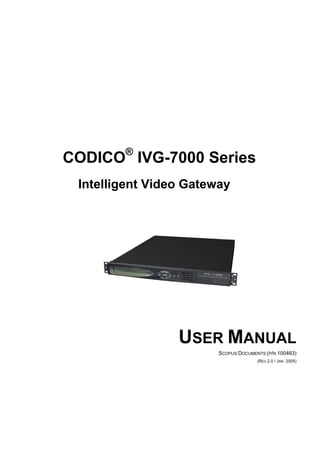
SlideShare a Scribd company logo
1 of 277
Download to read offline
CODICO®
IVG-7000 Series
Intelligent Video Gateway
USER MANUAL
SCOPUS DOCUMENTS (P/N 100463)
(REV 2.0 / JAN. 2005)
CODICO®
IVG-7000 Series
Intelligent Video Gateway
USER MANUAL
SCOPUS DOCUMENTS (P/N 100463)
(REV 2.0 / JAN. 2005)
Scopus Documents (p/n 100463) Page i
Scopus Network Technologies Inc.
U.S. Offices
Scopus Network Technologies Ltd.
International Headquarters
100 Overlook Center Drive, 3rd Floor
Princeton, NJ 08540.
USA
10 Ha’amal St., Park Afek
Rosh Ha’ayin, 48092
Israel
Tel: (609)-987-8090
Fax: (609)-987-8095
Tel: (972) –3-9007777
Fax: (972) –3-9007888
Email: info@scopususa.com
Web: www.scopususa.com
Email: info@scopus.net
Web: www.scopus.net
© 2001 Scopus Network Technologies Ltd. All rights reserved.
Scopus Network Technologies Ltd. Reserves the rights to alter the equipment specifications and descriptions in this publication without prior notice. No
part of this publication shall be deemed to be part of any contract or warranty unless specifically incorporated by reference into such contract or
warranty.
The information contained herein is merely descriptive in nature, and does not constitute a binding offer for sale of the product described herein.
Specifications and features sets are for technical information and are not legally biding.
CODICO®
is a Registered trademark of Scopus Network Technologies Ltd. In Israel, Germany, France, U.K. U.S.A. and Japan. All references to
registered trademarks of other vendors are the property of their respective owners.
File IVG-7000 User Rev 2.0. Saved 03/02/2005 12:40
CODICO®
IVG-7000 Series
Intelligent Video Gateway
Scopus Documents (p/n 100463) Page i
INTRODUCTION
Scopus Network Technologies Ltd. takes great pride in delivery of its products and
makes every endeavor to ensure its clients full satisfaction.
On behalf of the whole Scopus team, we would like to extend our congratulations
on your investment in the Scopus’ IVG-7000 Intelligent Video Gateway.
IVG-7000 INTELLIGENT VIDEO GATEWAY
User Manual
Front Matter
Page ii (Rev 2.0 / Jan. 2005)
MANUAL SCOPE AND STRUCTURE
The User Manual for the Scopus’ IVG-7000 Series of Integrated Video Gateways
provides instructions for qualified installation, service and operation technicians to
facilitate optimum performance of the IVN-7000 Series. The manual is comprised of
six main sections:
1. OVERVIEW:
This section provides an introduction and product description, including:
Highlights,
Benefits and typical applications,
Gives a functional and physical description of the unit
Lists its main capabilities and specifications.
2. INSTALLATION:
This section provides data and procedures required to install and activate the
unit.
3. THEORY OF OPERATION:
This section provides instructions for IVG-7000 key elements and procedures.
4. IVG-7000 FRONT PANEL INTERFACE:
The IVG-7000 Front Panel provides a Man-Machine Interface between the
IVG-7000 local operator and the IVG-7000. This section details the tools
provided from the Front Panel to the local operator of the IVG-7000 Series.
5. IVG-7000 COMMAND LINE INTERFACE (CLI):
The IVG-7000 Series CLI is a textual command line interface, operated
through a terminal connected to the IVG-7000. This section provides an
introduction to the CLI and a detailed description of the IVG-7000 CLI
commands.
6. IVG-7000 ELEMENT MANAGEMENT SYSTEM (EMS) INTERFACE:
The IVG-7000 EMS is a Graphical User Interface (GUI) for the remote
operation of the IVG-7000. This section provides operating directives to the
IVG-7000 EMS operators and a detailed description of the IVG-7000 EMS
functions and tools.
It is assumed throughout this manual that personnel have a general knowledge
about the Scopus Intelligent Video Network™ Concept and architecture and the
Scopus IVG-7000 Series, its application, and capabilities.
CODICO®
IVG-7000 Series
Intelligent Video Gateway
Scopus Documents (p/n 100463) Page iii
CONVENTIONS AND TERMINOLOGY
The following general conventions are used in this manual:
CONVENTION EXPLANATION
Function and
other Keys
Square brackets indicate a keyboard key, e.g. [F1].
Mouse Buttons A standard mouse has two or three mouse buttons. These
buttons are used to select options in the program main
interface. ‘Click [OK]’ means to position the mouse cursor
over the OK button and then press and release the left
mouse button.
Key
Combinations
A plus sign (+) indicates two keys that should be pressed
at the same time. For example [Alt]+[Tab] means hold
down the Alt key while pressing the Tab key.
Key Sequences The minus symbol (-) indicates keys that should be
pressed in sequence. For example, [Caps Lock]-[A]
means you should press and release the [Caps Lock] key
and then press and release the [A] key.
Tools Options may be accessed by pressing <Alt> together with
the Option Shortcut Key. Each shortcut key is underlined.
For example, to open the Tools menu, press [Alt]+[T].
File New Text written in this format indicates the command you
select from a menu on the menu bar. For example,
File New means that from the File menu you select the
New command.
CTRL + Mouse Hold down the [CTRL] key on your keyboard and select
multiple non-concurrent objects.
SHIFT + Mouse Hold down the [SHIFT] key on your keyboard and select
multiple concurrent objects.
User Manual
Front Matter
Page iv (Rev 2.0 / Jan. 2005)
TECHNICAL SUPPORT
In case of technical problems with the CODICO
system or one of its components,
refer to the System Documentation. Usually, this may save time in resolving
technical difficulties.
If you not be able to resolve the problem, call your local distributor for technical
support.
HOW TO RETURN FAULTY PARTS
Before Returning An Item:
• Request a RMA (Return Merchandise Authorisation) Tracking Number from
your local Distributor.
• Scopus Network Technologies Support will assign a RMA Tracking Number;
this must accompany the item being returned and will be referred to in all
correspondence.
• Send the item to Scopus Network Technologies with the RMA Number
included in the accompanying documentation (shipping and customs forms).
Customer Support Point Of Contact (POC)
Scopus Network Technologies Inc.
U.S. Offices
Scopus Network Technologies Ltd.
International Headquarters
100 Overlook Center Drive, 3rd Floor
Princeton, NJ 08540.
USA
10 Ha’amal St., Park Afek
Rosh Ha’ayin, 48092
Israel
Tel: (609)-987-8090
Fax: (609)-987-8095
Tel: (972) –3-9007777
Fax: (972) –3-9007888
Email: support@scopus.net
Web: www.scopus.net
CODICO®
IVG-7000 Series
Intelligent Video Gateway
Scopus Documents (p/n 100463) Page v
WARRANTY
SCOPUS Network Technologies Ltd. warrants that the Product and any part thereof, including, but
not limited to spare parts, will, when properly installed, conform to SCOPUS Network
Technologies Ltd. published specifications and that the Product and any parts thereof, including,
but not limited to, spare parts, will be free from defects deriving from wrong workmanship and
faulty materials under normal use and service, for a period of twelve (12) months following the
date of manufacture thereof.
The supply of spare parts at reasonable cost shall be available for a period of three (3) years from
the date of delivery.
This warranty does not cover ordinary wear and tear of the Product or other defects due to
circumstances beyond SCOPUS Network Technologies Ltd. control such as unsuitable operating
means, chemical, Electro-mechanical or electrical influences and damages which may be caused
by interference by the CUSTOMER or any unauthorized third party.
Defective cards/assemblies will be sent to SCOPUS Network Technologies Ltd. for repair. The
repaired cards/assemblies will be returned to the CUSTOMER within 30 days from their receipt by
SCOPUS Network Technologies Ltd.
Cards/assemblies repaired during the 12 months warranty period will carry a warranty of 6
months from date of repair or until end of original warranty period, whichever is the later date.
SCOPUS Network Technologies Ltd. sole liability under this warranty shall be limited to the repair
or replacement with equivalent units at SCOPUS Network Technologies Ltd. facilities, of any
Product or parts thereof that do not conform to SCOPUS Network Technologies Ltd. published
specifications or that are defective in material or workmanship, as specified above. The expense
of installing repaired or replaced parts shall be borne by the CUSTOMER.
SCOPUS Network Technologies Ltd. sole obligation under this Warranty is be the supplier of the
Product to the CUSTOMER and to provide such services as set out in this Warranty on the
SCOPUS Network Technologies Ltd. terms and conditions provided for herein. In no event will
SCOPUS Network Technologies Ltd. be liable to the CUSTOMER for any business expenses, loss of
profits, incidental, indirect or consequential damages, however caused, unless such expenses,
loss or damages shall have derived from an infringement of patents of copyrights.
THE WARRANTIES STATED HEREIN ARE EXCLUSIVE AND ARE EXPRESSLY IN LIEU OF ALL OTHER
WARRANTIES, EXPRESSED OR IMPLIED, INCLUDING, BUT NOT LIMITED TO, THE IMPLIED
WARRANTY OF MERCHANTABILITY OR FITNESS FOR A PARTICULAR PURPOSE.
Beyond the warranty period, SCOPUS Network Technologies Ltd. shall repair or replace defective
cards/assemblies according to its standard price list relevant at such time. Cards/assemblies thus
repaired shall carry a warranty of 6 months.
User Manual
Front Matter
Page vi (Rev 2.0 / Jan. 2005)
CE Certification
IVG-7000 meet all the CE Class B requirements with the exception of Emission
Requirements.
In order to meet CE requirements, the following cables must be connected on all
ASI outputs (ASI out 1, ASI out 2, ASI out 3). When cables are connected to these
outputs then the device is compliant with FAIR-RITE 0443164151.
FCC Compliance Notice
Trade Name Scopus
Product Name Intelligent Video Gateway
Product Model Number CODICO®
IVG-7000
These devices comply with Part 15 of the FCC Rules.
OPERATION IS SUBJECT TO THE FOLLOWING TWO CONDITIONS:
1. This device may not cause harmful interference.
2. This device must accept any interference received, including interference that
may cause undesired operation.
RESPONSIBLE PARTY:
RESPONSIBLE PARTY'S NAME
Address 100 Overlook Center Drive, 3rd Floor
Princeton, NJ 08540.
USA
Contact Tel: (609)-987-8090
Fax: (609)-987-8095
Email: info@scopususa.com
CODICO®
IVG-7000 Series
Intelligent Video Gateway
Scopus Documents (p/n 100463) Page vii
The FCC Wants You to Know
This equipment has been tested and found to comply with the limits for a Class B
digital device, pursuant to Part 15 of the FCC rules. These limits are designed to
Provide reasonable protection against harmful interference in a residential installation.
This equipment generates, uses and can radiate radio frequency energy and, If not
installed and used in accordance with the instructions, may cause harmful interference
to radio communications.
However, there is no guarantee that interference will not occur in a particular
installation. If this equipment does cause harmful interference to radio or television
reception, which can be determined by turning the equipment off end on, the user is
encouraged to try to correct the interference by one or more of the following
measures:
Reorient or relocate the receiving antenna.
Increase the separation between the equipment and receiver.
Connect the equipment to an outlet on a circuit different from that to which the
receiver is connected.
Consult the dealer or an experienced radio/TV technician.
FCC Warning
Modifications not expressly approved by the manufacturer could void the user
authority to operate the equipment under FCC Rules.
User Manual
Front Matter
Page viii (Rev 2.0 / Jan. 2005)
TABLE OF CONTENTS
TABLE OF CONTENTS............................................................................................. viii
LIST OF FIGURES ....................................................................................................xii
LIST OF TABLES...................................................................................................... xiv
Section 1 Overview..................................................................................... 1-1
1.1. General Information......................................................................................... 1-1
1.2. Scopus Intelligent Video Network (IVNTM
) Concept....................................... 1-3
1.2.1. The Scopus IVNTM
Architecture ......................................................... 1-3
1.2.2. IVG-7000 Technology Edge .............................................................. 1-5
1.2.3. Scopus IVG-7000 Series of Intelligent Video Gateways ........................ 1-7
1.2.4. IVG-7000 Highlights and Benefits...................................................... 1-7
1.3. Applications..................................................................................................... 1-10
1.3.1. IVNTM
Head-End and Distributed Backbone Solution........................... 1-10
1.3.2. C & D Solutions using the IVG-7000 Platform ................................... 1-11
1.3.3. IVG-7000 Head-End Clustering Solutions ......................................... 1-13
1.3.4. Intelligent Regional/Edge Head-End Solution .................................... 1-14
1.3.5. Intelligent Digital Turnaround (DTA) Application ............................... 1-15
1.3.6. IP Streaming Application................................................................ 1-15
1.3.7. Conditional Access ........................................................................ 1-16
1.3.8. Digital Ad-Insertion Application....................................................... 1-17
1.3.9. Network and Element Management System...................................... 1-18
1.4. Functional Description.................................................................................... 1-21
1.4.1. Basic and Custom Configurations .................................................... 1-21
1.4.2. Functional Architecture .................................................................. 1-23
1.4.3. Mechanical Structure ..................................................................... 1-24
1.5. Capabilities and Specifications ...................................................................... 1-27
1.5.1. Product Capabilities....................................................................... 1-27
1.5.2. Product Technical Specifications...................................................... 1-28
1.5.3. Product Physical Specifications........................................................ 1-28
Section 2 Installation................................................................................. 2-1
2.1. Introduction ...................................................................................................... 2-1
2.1.1. Safety Precautions .......................................................................... 2-1
2.1.2. Inventory Check ............................................................................. 2-1
2.2. Site Preparation................................................................................................ 2-2
2.3. Installation........................................................................................................ 2-2
2.3.1. Installation in 19" Rack.................................................................... 2-2
2.4. Cable Connections............................................................................................ 2-3
2.4.1. IVG-7000 Series Connection Setup and Options.................................. 2-3
2.4.2. Power Connection ........................................................................... 2-4
2.5. IVG Software Update Procedure ..................................................................... 2-5
2.6. Initialization And Configuration....................................................................... 2-7
2.6.1. Powering Up................................................................................... 2-7
2.6.2. Initialization Sequence..................................................................... 2-7
2.6.3. Initial Parameters Set-up ................................................................. 2-7
CODICO®
IVG-7000 Series
Intelligent Video Gateway
Scopus Documents (p/n 100463) Page ix
Section 3 Operational Processes.............................................................. 3-1
3.1. General ..............................................................................................................3-1
3.2. Cross-Connect...................................................................................................3-1
3.2.1. Transrating.....................................................................................3-2
3.2.2. Preprovision ...................................................................................3-2
Section 4 IVG-7000 Front Panel Interface............................................. 4-1
4.1. IVG-7000 Front Panel.......................................................................................4-1
4.2. Front Panel Menu Operational Concept...........................................................4-2
4.2.1. Screen Types..................................................................................4-2
4.2.2. Keypad Control ...............................................................................4-3
4.2.3. Default Screen................................................................................4-4
4.2.4. Front Panel Tree..............................................................................4-4
4.3. Main Menu .........................................................................................................4-6
4.4. Configuration Menu...........................................................................................4-7
4.4.1. IP Addressing .................................................................................4-7
4.4.2. ASI Input Ports ...............................................................................4-8
4.4.3. ASI Output Port ..............................................................................4-9
4.5. Input Streams Menu.......................................................................................4-11
4.5.1. Input Ports Table .......................................................................... 4-11
4.5.2. Input Transport Streams Table ....................................................... 4-12
4.5.3. Input Services Table...................................................................... 4-12
4.5.4. Input Service Management............................................................. 4-13
4.6. Output Streams Menu ....................................................................................4-14
4.6.1. Output Ports Table ........................................................................ 4-14
4.6.2. Output Transport Streams Table ..................................................... 4-15
4.6.3. Output Services Table.................................................................... 4-15
4.6.4. Output Service Management........................................................... 4-16
4.7. Monitoring Menu .............................................................................................4-16
4.7.1. Event Log..................................................................................... 4-17
4.7.2. Chassis Health .............................................................................. 4-17
4.8. Actions & Procedures Menu............................................................................4-18
4.8.1. Reset Unit .................................................................................... 4-18
4.8.2. Remove All Cross Connections ........................................................ 4-18
4.9. Unit Information Menu ...................................................................................4-19
4.9.1. Unit Identity ................................................................................. 4-19
4.9.2. Software Versions ......................................................................... 4-19
4.9.3. License ........................................................................................ 4-20
4.9.4. Unit Time ..................................................................................... 4-20
Section 5 IVG-7000 Command Line Interface....................................... 5-1
5.1. General ..............................................................................................................5-1
5.1.1. Preparing the CLI ............................................................................5-1
5.1.2. CLI Navigation and Operation Guidelines............................................5-3
5.1.3. CLI Command Structure...................................................................5-5
5.1.4. IVG-7000 Initialization Sequence ......................................................5-5
5.2. Monitoring Commands......................................................................................5-6
5.2.1. Input Monitoring Commands.............................................................5-6
5.2.2. Output Monitoring Commands......................................................... 5-13
User Manual
Front Matter
Page x (Rev 2.0 / Jan. 2005)
5.2.3. Cross Connections Monitoring Commands ........................................ 5-17
5.2.4. Statistics Monitoring Commands ..................................................... 5-22
5.2.5. filesystm Commands ..................................................................... 5-24
5.2.6. Ethernet Monitoring Commands ...................................................... 5-29
5.2.7. Logger Monitoring Commands ........................................................ 5-30
5.2.8. System Monitoring Commands ....................................................... 5-31
5.2.9. CAS Monitoring Commands ............................................................ 5-32
5.2.10. Descriptors Commands ................................................................ 5-33
5.2.11. PSI_SI Commands ...................................................................... 5-36
5.2.12. Scrambling Commands ................................................................ 5-36
5.2.13. Clock Commands ........................................................................ 5-37
5.3. Configuration Commands .............................................................................. 5-38
5.3.1. Input Configuration Commands ...................................................... 5-38
5.3.2. Output Configurations Commands................................................... 5-40
5.3.3. Scrambling Configuration............................................................... 5-48
5.3.4. Cross connect Commands .............................................................. 5-51
5.3.5. Statistics Configuration Commands ................................................. 5-59
5.3.6. Filesystem Commands................................................................... 5-61
5.3.7. Ethernet Configurations Commands................................................. 5-66
5.3.8. Logger Configuration Commands .................................................... 5-68
5.3.9. CAS Monitoring Command.............................................................. 5-69
5.3.10. Clock Commands ........................................................................ 5-73
5.3.11. Descriptors Commands ................................................................ 5-76
5.3.12. PSI_SI Commands ...................................................................... 5-81
5.4. Administration Commands ............................................................................ 5-82
5.4.1. users Command............................................................................ 5-82
5.4.2. timeout command......................................................................... 5-82
5.4.3. change_password command........................................................... 5-82
5.4.4. new_user command ...................................................................... 5-83
5.4.5. delete_user command ................................................................... 5-83
5.4.6. ping command.............................................................................. 5-83
5.4.7. connections command ................................................................... 5-84
5.4.8. drop_connection command ............................................................ 5-84
5.4.9. get_product_id command .............................................................. 5-84
5.4.10. show_license_key command......................................................... 5-84
5.4.11. set_license_key command............................................................ 5-85
5.5. Reset Commands ........................................................................................... 5-86
5.5.1. factory_default Command .............................................................. 5-86
5.5.2. restart Command.......................................................................... 5-86
Section 6 IVG-7000 Element Management System.............................. 6-1
6.1. Introduction ...................................................................................................... 6-1
6.1.1. Starting the EMS............................................................................. 6-2
6.1.2. EMS Main screen............................................................................. 6-5
6.1.3. Platform Environment...................................................................... 6-8
6.1.4. Saving Configuration Changes (IVG Management) ............................ 6-10
6.2. Device Panel (IVG Management) .................................................................. 6-11
6.3. Configuration (IVG Management)................................................................. 6-15
6.3.1. Entity (IVG Management) .............................................................. 6-17
CODICO®
IVG-7000 Series
Intelligent Video Gateway
Scopus Documents (p/n 100463) Page xi
6.3.2. Host Information (IVG Management) ............................................... 6-19
6.3.3. License Permissions (IVG Management) ........................................... 6-21
6.3.4. Snmp Statistics (IVG Management) ................................................. 6-23
6.3.5. System Information (IVG Management)........................................... 6-25
6.4. Bit Rate Chart (IVG Management) ................................................................6-26
6.5. Stream Information (IVG Management).......................................................6-28
6.5.1. General........................................................................................ 6-28
6.5.2. ASI IN Configuration (Stream Information) ...................................... 6-33
6.5.3. ASI OUT Configuration (Stream Information).................................... 6-45
6.5.4. GbE Configuration (Stream Information) .......................................... 6-56
6.6. Cross Connection Wizard (IVG Management) ..............................................6-69
6.6.1. Step one: Selecting a Source (Cross Connection Wizard).................... 6-70
6.6.2. Step Two: Selecting a Target (Cross Connection Wizard).................... 6-72
6.6.3. Step Three: Validity Checking (Cross Connection Wizard)................... 6-73
6.6.4. Step Four: Program Editing (Cross Connection Wizard) ...................... 6-74
6.6.5. Step Five: PID Editing (Cross Connection Wizard) ............................. 6-76
6.6.6. Step Six: Cross Connection Activation (Cross Connection Wizard) ....... 6-77
6.7. ASI IN Port Management ...............................................................................6-78
6.7.1. Bandwidth Chart (ASI IN)............................................................... 6-78
6.7.2. Configuration (ASI IN) ................................................................... 6-80
6.8. ASI OUT Port Management ............................................................................6-83
6.8.1. Bandwidth Chart (ASI OUT)............................................................ 6-83
6.8.2. Configuration (ASI OUT) ................................................................ 6-84
6.9. Giga-Bit Ethernet (GbE) .................................................................................6-89
6.9.1. Configuration (GbE)....................................................................... 6-89
6.10. Management Ports and Environment Configuration ....................................6-93
6.10.1. Fast Ethernet Port Configuration.................................................... 6-93
6.10.2. Fan Management......................................................................... 6-94
6.10.3. Power Supply Management........................................................... 6-94
6.11. Conditional Access ..........................................................................................6-94
6.11.1. Adding an ECM Generator............................................................. 6-95
6.11.2. Remove an ECM Generator ........................................................... 6-98
6.11.3. Adding an EMM Generator ............................................................ 6-98
6.11.4. Remove an EMM Generator......................................................... 6-102
6.11.5. Scrambling settings ................................................................... 6-102
6.11.6. Cross Connecting Pre-Encrypted Programs ................................... 6-106
6.11.7. CA Parameters Display............................................................... 6-107
User Manual
Front Matter
Page xii (Rev 2.0 / Jan. 2005)
LIST OF FIGURES
Figure 1-1: The Scopus IVG-7000 Platform – General View......................................... 1-2
Figure 1-2: The Scopus IVNTM
Solution ...................................................................... 1-4
Figure 1-3: The IVG-7000 Series in an IVNTM
Backbone Solution.................................1-10
Figure 1-4: Content Contribution and Distribution over IP Networks ...........................1-11
Figure 1-5: IVG-7000 Head-End Clustering Solutions .................................................1-13
Figure 1-6: Intelligent Regional/Edge Head-End Solution ...........................................1-14
Figure 1-7: The IVG-7300 in an Intelligent Digital Turnaround Application ..................1-15
Figure 1-8: The IVG-7400 in a Broadband IP Streaming Application ...........................1-16
Figure 1-9: IVG-7000 Simulcrypt V.3 Interfaces ........................................................1-17
Figure 1-10: IVG-7000 in an Ad-Insertion Application..................................................1-18
Figure 1-11: IVG-7000 Series EMS .............................................................................1-19
Figure 1-12: Moving Up in the TMN Layers .................................................................1-20
Figure 1-13: IVG-7000 Basic Configuration Functional Block Diagram ...........................1-24
Figure 1-14: IVG-7000 Front Panel.............................................................................1-25
Figure 1-15: IVG-7000 Series of Intelligent Video Gateways - Rear View ......................1-25
Figure 2-1: IVG-7000 Series of Intelligent Video Gateways - Rear View ....................... 2-3
Figure 2-2: IVG-7000 Jack Screw Ground Connection ................................................. 2-4
Figure 4-1: IVG-7000 Front Panel.............................................................................. 4-1
Figure 4-2: Edit Menu Example ................................................................................. 4-2
Figure 4-3: Table Menu Example............................................................................... 4-3
Figure 4-4: Simple Edit Screen Example..................................................................... 4-3
Figure 4-5: Multiple Choices Edit Screen Example....................................................... 4-3
Figure 4-6: Main Screen............................................................................................ 4-4
Figure 4-7: Front Panel Tree ..................................................................................... 4-5
Figure 4-8: Main Menu Display.................................................................................. 4-6
Figure 4-9: Configuration Menu Display ..................................................................... 4-7
Figure 4-10: IP Addressing Menu Display..................................................................... 4-7
Figure 4-11: IP Address Edit Menu Display................................................................... 4-8
Figure 4-12: ASI Input Ports - Table Menu Display....................................................... 4-9
Figure 4-13: ASI Output Port Table Menu Display ........................................................ 4-9
Figure 4-14: ASI Output Port Edit Menu Display..........................................................4-10
Figure 4-15: Input Port Table Menu Display................................................................4-11
Figure 4-16: Input Transport Stream - Table Menu Display..........................................4-12
Figure 4-17: Input Services - Table Menu Display........................................................4-12
Figure 4-18: Input Service – Edit Menu Display...........................................................4-13
Figure 4-19: Output Ports - Table Menu Display..........................................................4-14
Figure 4-20: Output Transport Stream – Table Menu Display.......................................4-15
Figure 4-21: Output Services - Table Menu Display .....................................................4-15
Figure 4-22: Output Service Management - Edit Menu Display .....................................4-16
Figure 4-23: Monitoring - Menu Display ......................................................................4-16
Figure 4-24: Event Log Display ..................................................................................4-17
Figure 4-25: Chassis Temperature Menu.....................................................................4-17
Figure 4-26: Actions & Procedures Menu Display.........................................................4-18
Figure 4-27: Unit Information Menu Display................................................................4-19
Figure 4-28: License Menu Display .............................................................................4-20
CODICO®
IVG-7000 Series
Intelligent Video Gateway
Scopus Documents (p/n 100463) Page xiii
Figure 4-29: License Menu Display............................................................................. 4-20
Figure 5-1: COM x Properties Dialog Box....................................................................5-2
Figure 5-2: IVG-7000 Menu Tree Structure.................................................................5-5
Figure 6-1: EMS Graphical User Interface ...................................................................6-1
Figure 6-2: Mount Wizard –Step 1 .............................................................................6-3
Figure 6-3: Mount Wizard –Step 2 .............................................................................6-3
Figure 6-4: Mount Wizard –Step 3 .............................................................................6-4
Figure 6-5: EMS Main Screen.....................................................................................6-5
Figure 6-6: EMS Tool Bar ..........................................................................................6-7
Figure 6-7: Explorer Window .....................................................................................6-8
Figure 6-8: A Window Example..................................................................................6-9
Figure 6-9: Save Command ..................................................................................... 6-10
Figure 6-10: IVG-7000 Management .......................................................................... 6-11
Figure 6-11: Device Panel Window: IVG-7000 with two outputs................................... 6-12
Figure 6-12: Device Panel Window: IVG-7000 with four outputs.................................. 6-12
Figure 6-13: IVG Configuration.................................................................................. 6-15
Figure 6-14: Configuration Window............................................................................ 6-16
Figure 6-15: Entity Window....................................................................................... 6-18
Figure 6-16: Host Information window....................................................................... 6-20
Figure 6-17: License Permissions window................................................................... 6-22
Figure 6-18: SNMP Statistics Window......................................................................... 6-24
Figure 6-19: System Information window................................................................... 6-26
Figure 6-20: Bit Rate Chart........................................................................................ 6-27
Figure 6-21: IVG Context Menu ................................................................................ 6-28
Figure 6-22: Stream Information Window .................................................................. 6-29
Figure 6-23: Gigabit Ethernet Context Menu............................................................... 6-30
Figure 6-24: Logical Interface parameters dialog ........................................................ 6-30
Figure 6-25: I/O Tree Context Menu .......................................................................... 6-32
Figure 6-26: ASI IN Parameters................................................................................. 6-33
Figure 6-27: ASI IN-Port Parameters.......................................................................... 6-35
Figure 6-28: ASI IN-Network Parameters ................................................................... 6-37
Figure 6-29: ASI IN-Stream Parameters ..................................................................... 6-39
Figure 6-30: ASI IN-Service Parameters ..................................................................... 6-41
Figure 6-31: ASI IN- Elementary Stream Parameters .................................................. 6-43
Figure 6-32: ASI OUT Parameters.............................................................................. 6-45
Figure 6-33: ASI OUT-Port parameters....................................................................... 6-46
Figure 6-34: ASI OUT-Network Parameters ................................................................ 6-48
Figure 6-35: ASI OUT-Stream Parameters .................................................................. 6-50
Figure 6-36: ASI OUT-Service Parameters.................................................................. 6-52
Figure 6-37: ASI OUT-PID Parameters ....................................................................... 6-54
Figure 6-38: GbE Parameters .................................................................................... 6-56
Figure 6-39: GbE-Broadcast Parameters..................................................................... 6-58
Figure 6-40: GbE Network Parameters ....................................................................... 6-60
Figure 6-41: GbE-Stream Menu Parameters................................................................ 6-62
Figure 6-42: GbE-Service Parameters......................................................................... 6-64
Figure 6-43: GbE-PID Parameters.............................................................................. 6-66
Figure 6-44: Cross Connection Wizard........................................................................ 6-69
Figure 6-45: Cross Connection Wizard Step one: Selecting a source............................. 6-71
Figure 6-46: Cross Connection Wizard Step two: Selecting a Target............................. 6-72
User Manual
Front Matter
Page xiv (Rev 2.0 / Jan. 2005)
Figure 6-47: Cross Connection Wizard Step three: Validation Check .............................6-73
Figure 6-48: Cross Connection Wizard Step four: Program Editing with Joint Transrating6-75
Figure 6-49: PID Editing ............................................................................................6-75
Figure 6-50: Cross Connection Wizard Step five: PID Editing .......................................6-76
Figure 6-51: Cross Connection Wizard Step Six: Cross Connection Activation ................6-77
Figure 6-52: Bandwidth Chart Window (ASI IN) ..........................................................6-79
Figure 6-53: Port Configuration Window (ASI IN)........................................................6-81
Figure 6-54: DVB IN Window (ASI IN)........................................................................6-82
Figure 6-55: Bandwidth Chart Window (ASI OUT) .......................................................6-84
Figure 6-56: Port DVB Configuration Window (ASI OUT)..............................................6-86
Figure 6-57: EMM Output PID Wizard dialog ...............................................................6-87
Figure 6-58: EMM Output PID (ASI OUT)....................................................................6-88
Figure 6-59: IP Address Window (GbE) ......................................................................6-90
Figure 6-60: Port Configuration (GbE) ........................................................................6-92
Figure 6-61: CA Configuration Window.......................................................................6-96
Figure 6-62: ECM Generator Wizard ...........................................................................6-97
Figure 6-63: ECM Generator display ...........................................................................6-98
Figure 6-64: EMM Generator context menu.................................................................6-99
Figure 6-65: EMM Generator wizard .........................................................................6-100
Figure 6-66: EMM Generator display.........................................................................6-102
Figure 6-67: Scrambling context menu .....................................................................6-103
Figure 6-68: Scrambling settings dialog box..............................................................6-104
Figure 6-69: Add Scrambling dialog box ...................................................................6-105
Figure 6-70: Cross connecting an EMM.....................................................................6-107
Figure 6-71: ECM parameters Display.......................................................................6-108
Figure 6-72: EMM parameters Display ......................................................................6-109
LIST OF TABLES
Table 1-1: IVG-7000 Series Configuration Options....................................................1-22
Table 1-2: IVG-7000 Series - Typical Connector Interfaces .......................................1-26
Table 1-3: IVG-7000 Series of Intelligent Video Gateways ........................................1-28
Table 2-1: IVG-7000 Series - Typical Connector Interfaces ........................................ 2-3
Table 5-1: Default Accounts in the CLI ..................................................................... 5-3
Table 6-1: EMS Menu Bar ........................................................................................ 6-6
Table 6-2: Device Panel Management......................................................................6-13
Table 6-3: Entity Parameters ..................................................................................6-17
Table 6-4: Host Information Parameters..................................................................6-19
Table 6-5: License Permissions Parameters..............................................................6-21
Table 6-6: SNMP Statistics Parameters ....................................................................6-23
Table 6-7: System Information Parameters..............................................................6-25
Table 6-8: Stream Information Context Menu Items.................................................6-31
Table 6-9: ASI IN Parameters Description................................................................6-34
Table 6-10: ASI IN-Port Parameters Description.........................................................6-36
Table 6-11: ASI IN-Network Parameters Description ..................................................6-38
Table 6-12: ASI IN-Stream Parameters Description ....................................................6-40
Table 6-13: ASI IN-Service Parameters Description ....................................................6-42
Table 6-14: ASI IN- Elementary Stream Parameters Description..................................6-44
CODICO®
IVG-7000 Series
Intelligent Video Gateway
Scopus Documents (p/n 100463) Page xv
Table 6-15: ASI OUT Parameters Description ............................................................ 6-46
Table 6-16: ASI OUT-Port Parameters Description ..................................................... 6-47
Table 6-17: ASI OUT-Network Parameters Description............................................... 6-49
Table 6-18: ASI OUT-Stream Parameters Description................................................. 6-51
Table 6-19: ASI OUT-Service Parameters Description................................................. 6-53
Table 6-20: ASI OUT-PID Parameters Description...................................................... 6-55
Table 6-21: GbE Parameters Description................................................................... 6-57
Table 6-22: GbE-Broadcast Parameters Descriptions.................................................. 6-59
Table 6-23: GbE-Network Parameters Descriptions .................................................... 6-61
Table 6-24: GbE-Stream Parameters Descriptions...................................................... 6-63
Table 6-25: GbE-Service Parameters Descriptions...................................................... 6-65
Table 6-26: GbE-PID Parameters Descriptions........................................................... 6-67
Table 6-27: Port DVB Configuration Parameters ........................................................ 6-68
Table 6-28: Port DVB Configuration Parameters (ASI OUT) ........................................ 6-85
Table 6-29: EMM Output PID Wizard dialog parameters............................................. 6-88
Table 6-30: EMM Output PID (ASI OUT) ................................................................... 6-88
Table 6-31: IP Address Parameters (GbE) ................................................................. 6-91
Table 6-32: ECM General wizard parameters ............................................................. 6-97
Table 6-33: EMM General wizard parameters .......................................................... 6-101
Table 6-34: Add Scrambling dialog parameters........................................................ 6-106
CODICO®
IVG-7000 Series
Intelligent Video Gateway
Scopus Documents (p/n 100463) Page 1-1
Section 1
OVERVIEW
1.1. GENERAL INFORMATION
The Scopus IVG-7000 Series of Intelligent Video Gateways is part of Scopus’ 4th
generation product line. It is the cornerstone of the Scopus Intelligent Video
Network (IVNTM
) architecture, which provides a powerful, yet cost effective solution
for the delivery of digital TV content and on-demand services over broadband
network infrastructures.
The IVG-7000 Series offers a new and sophisticated video routing and processing
platform that provides the core building blocks for the next generation of network
architectures. As such, the 1 RU slim-size IVG-7000 platform enables service
providers to deploy broadband, broadcast, and on-demand services over their
current and future infrastructure.
The IVG-7000 Series consists of the following application oriented members:
a. The Scopus IVG-7100 Intelligent Head-End Video Gateway
A scalable “Head-End in a Box” solution for the most advanced head-end
services.
b. The Scopus IVG-7200 Intelligent Edge Video Gateway
The edge device for video distribution over a backbone network (typically IP).
c. The Scopus IVG-7300 Intelligent Video Re-Multiplexer
Provides powerful transport stream processing with comprehensive digital
turnaround solutions.
d. The Scopus IVG-7400 Intelligent Broadband IP Streamer
Features grooming and delivery of Digital TV content over IP networks for
TV-over-DSL and FTTH networks.
User Manual
Overview
Page 1-2 (Rev 2.0 / Jan. 2005)
Figure 1-1: The Scopus IVG-7000 Platform – General View
The following is a list of some of the main features provided by the IVG-7000
Series:
• Multiple inputs and outputs (ASI, GbE) providing full video routing and
grooming to the PID level.
• Networking support for routing Video and Data over IP/ATM infrastructure.
• Distributed architecture using BoB (Broadcast over Broadband) technology
for networking and packet de-jittering.
• Built in DVB-Scrambling, Simulcrypt V.3 and Open CAS support..
• Full head-end integration including CA integration, PSI/SI and PSIP
processing and insertion.
• Digital to Digital processing including:
- Bit Rate Transcoding (SD and HD)
- Joint Transrating (JT); statistical re-multiplexing for bandwidth optimization
of multiple video services
- VBR CBR rate shaping
• End-to-End SNMP management for the entire network down to Service and
PID level.
• Advanced redundancy solutions eliminating the need of external matrix.
• Aggregate inputs rate up to 2.5 Gbps and outputs rate up to 2 Gbps (version
dependent).
• DVB over IP streaming for Telco DTH applications (using GbE output).
• Seamless clustering of several IVG-7100 Head-End units using a standard
GbE switch, with single entity management.
• Slim-line 1RU design with remarkable port density:
- Up to 16 ASI inputs
- Up to 6 ASI outputs
- Gigabit Ethernet port (input or output)
CODICO®
IVG-7000 Series
Intelligent Video Gateway
Scopus Documents (p/n 100463) Page 1-3
1.2. SCOPUS INTELLIGENT VIDEO NETWORK
(IVNTM
) CONCEPT
The Scopus Intelligent Video Network (IVNTM
) concept represents the next
generation for cable video networking. IVNTM
provides a new perspective for the
video world: It handles video in the same way that data and the voice are handled,
via video routing.
The IVNTM
concept answers the needs of both DTH broadcasters and video C&D
service providers. Distributed and scalable, the IVNTM
uses patented technology to
route video over the network. Due to its network homogeneity, the IVNTM
also
provides low cost solutions per service and lowers OPEX. Its distributed architecture
management system, based on state of the art technologies, assists cable
operators to advance into a new world of management. Scopus IVNTM
solution is
capable of controlling the whole spectrum as well as managing flexible, scalable
solutions for gradual deployment.
1.2.1. The Scopus IVNTM
Architecture
The Scopus IVNTM
comprehensive architecture utilizes the entire network
infrastructure and enables two-dimensional control over bandwidth to support end-
to-end solutions - from the Master Head-End, through the network backbone, up to
the Regional Head-Ends and down to the nodes.
Scopus IVNTM
solution replaces the limited capabilities of the traditional multiplexers
with intelligent networks based on Intelligent Video Gateways (IVGs). The
IVG-7000 provides digital-to-digital processing and supports different types of
backbones (ATM or IP oriented) as well as QAM outputs for Hybrid Fiber-Coaxial
(HFC) networks. A single management system, working at the service level, yields
additional advantages, especially when the network supports many services along
the transmission chain, such as service restoration by routing content from one
node to the other.
User Manual
Overview
Page 1-4 (Rev 2.0 / Jan. 2005)
Figure 1-2: The Scopus IVNTM
Solution
Video
Server
Billing
SMS
Video
Server
NODE
NODE
NODE
HUB
Video
Server
Remote HE
Master HE
IRD
Enc
Enc
CID
IVG 7100
Video
Server
NODE
NODE
NODE
HUB
Video
Server
NODE
NODE
NODE
HUB
HUB
HUB
IP Network
IVG 7200
IVG 7200
IVG 7200
IVG 7200
1.2.1.1. Head-Ends
Scopus IVNTM
represents the next generation of head ends. The core of the head
end will be the IVG-7100 for supporting broadcasting content as well as
personalized services. For a scalable solution, several IVGs can be aggregated to
create a head end in a box, offering complete processing, re-mapping, transrating,
and a statistical multiplexing solution that handles locally encoded and off-air pre-
compressed content. This solution relies on GbE switch as an internal matrix,
eliminating the requirement for external digital matrixes. And once this is
integrated with Conditional Access platforms, IVNTM
becomes a head end, directly
addressing digital pay TV delivery and video on-demand applications.
1.2.1.2. Backbone
IVNTM
uses a Giga Bit Ethernet (GbE) IP based protocol to provide a cost effective
solution comparable to current ATM and SONET/SDH networks.
The GbE IP protocol enables utilization of the strengths of the data world to route
services, as opposed to the traditional broadcasting world. In addition, the network
supports future developments, such as multicast transmission to subscriber homes.
The IVNTM
is designed for IP networks and employs internal mechanisms to handle
jittering over the backbone and incorporate multicast / unicast capabilities for
contribution and distribution.
1.2.1.3. Edge Processing
Edge Processing is the future direction for networks with a ‘steadily growing hunger’
for bandwidth. Edge processing is a natural migration path from today trans-
CODICO®
IVG-7000 Series
Intelligent Video Gateway
Scopus Documents (p/n 100463) Page 1-5
modulators at the edges to smart edge devices based on generic platforms ready
for tomorrow’s needs.
The IVNTM
devices act as ”smart” edges for providing content processing, rate
reduction, grooming and re-multiplexing for new bouquet creation. Their output
signals are transmitted over the HFC using QAM.
The Edge device improves access network utilization with transrating and
transcoding capabilities, supports sliced advertisements or segmented localized
content and enables connectivity with On-demand Applications (ODA). They also
enable dynamic bandwidth allocation, broadcast channel switching and create
dynamic spectrum allocation according to subscriber request. Simply put, the IVNTM
permits cable operators to cost effectively deploy personal services at their own
pace.
In addition to processing capabilities, Edge units can function as distributed
monitoring systems replacing the less preferable solution based on subscribers
reports. Video quality and transport regularity will also be monitored by the Edge
units and reported to the head-end for better allocation (transrating, transcoding)
of resources at the head-end.
1.2.1.4. Management
The NMS-7000 management system manages content flow and enables the IVNTM
to perform video routing. Working in the services level rather than on the
traditional devices level, the IVNTM
is positioned to control and distribute content in
the most efficient way.
Traditional service delivery upholding is based on box-level redundancy at the
head-end level. The IVNTM
concept replaces this with a more logical ”philosophy of
service level restoration” process based on Content Redundancy between head-
ends. The NMS-7000 manages the content flow over the backbone and at the HFC
Network, enabling head-ends to provide redundancy for each other and to facilitate
quick routing of services in case of any particular head-end failure.
1.2.2. IVG-7000 Technology Edge
The Scopus IVG-7000 Intelligent Video Gateway is a new and sophisticated
platform for video routing and processing. It provides the following technology
features:
1. Video Routing And Processing
Featuring a breakthrough patent pending network processing technology, the
IVG-7000 platform is capable of processing up to 4Gbps of video and data, all
in a 1RU enclosure. Its capability of aggregating multiple units over a GbE
switch, while maintaining management as a single entity, allows it to
significantly scale up processing power for hundreds of streams and services.
2. Bit-Rate Reduction And Joint Rate Allocation (JRA)
The IVG-7000 platform provides best of breed digital video processing
capabilities, such as bit rate reduction and statistical re-multiplexing, on any
of its outputs. The JRA capability of the IVG-7000 enables combining rate
User Manual
Overview
Page 1-6 (Rev 2.0 / Jan. 2005)
controlled local encoders with rate reduced DTA services in the same
statistical multiplexing group, for most efficient and flexible bandwidth
allocation and management.
3. Conditional Access and Head-End Interfacing
The IVG-7000 features built in DVB scramblers per each output and seamless
integration with Conditional Access Systems using Simulcrypt open system
architecture. The IVG-7000 provides the full Simulcrypt V.3 functionality for
interfaces with ECM and EMM generators, as well as EIS schedulers and
PSI/SI generators. Adding its flexible PSI/SI generation and insertion
capabilities, the IVG-7000 forms the ultimate head-end unit for current and
future digital video applications.
45.On-demand Solutions
The On-Demand world, with its Video On-demand (VOD) flagship, is
challenging the bandwidth utilization and management to new levels. The
IVG-7000 Series is designed to integrate with video servers and on-demand
applications, utilizing DSA™ dynamic session allocation technology for
optimized use of bandwidth resources to balance broadcast and on-demand
services.
5. Digital Program Insertion
Seamless splicing as well as support of DPI standards SCTE 30 (DVS-380)
and SCTE 35 (DVS-253) will enable the compatibility of the IVG-7000 Series
with major ad server providers for an integrated Ad-Insertion solution.
6. IVG-7000 Management
The IVG-7000 platform provides top-of-the line management using friendly
and intuitive local and remote management tools.
The IVG-7000 Front Panel Control provides extended monitoring and control
features for local management, including alpha-graphic display and full
numerical keyboard as well as a navigation keypad for menu driven
operation.
The Command Line Interface (CLI) provides the local, or a remote operator,
the tools to monitor, configure and control the IVG-7000 using a PC
based terminal. Interface to the IVG-7000 is provided over RS-232 or as
standard Telnet client.
The IVG-7000 Element Management System uses SNMP commands to
provide an extensive graphic user interfaces (GUI) for managing the
IVG-7000 from dedicated EMS terminal or from the CODICO®
NMS-4000
and the new TMN based NMS-7000 network management systems.
CODICO®
IVG-7000 Series
Intelligent Video Gateway
Scopus Documents (p/n 100463) Page 1-7
1.2.3. Scopus IVG-7000 Series of Intelligent Video
Gateways
The IVG-7000 Series of Intelligent Video Gateways features the following
application oriented members:
1. IVG-7100 Intelligent Head-End Video Gateway
The IVG-7100 provides a scalable “Head-End in a Box” solution for the most
advanced head-end services. It is the basic building block of the IVNTM
architecture and is designed to interface with the essential head-end and
network element, to support hundred of services, to provide advanced video
processing capabilities and to enable and control advanced personal and on-
demand services. Multiple IVG-7100 units may be clustered over a GbE
switch and managed as single entity to provide optimized bandwidth
utilization and to simplify network management.
2. IVG-7200 Intelligent Edge Video Gateway
The IVG-7200 is located at the secondary head-end or the local hub in the
IVNTM distributed solution. It is used as the edge device for video distribution
over a backbone network (typically IP). It provides cost effective solutions for
distributed and local video processing and on-demand features as well as
QAM modulation and up-conversion capabilities for video distribution over
HFC networks.
3. IVG-7300 Intelligent Video Re-Multiplexer
The IVG-7300 is providing powerful transport stream processing with
comprehensive digital turnaround solutions. It features advanced digital
processing, bit-rate reduction, flexible grooming, statistical re-multiplexing
and multi-input to multi-output routing capabilities for extensive transport
stream management. The extensive DTA solutions the IVG-7300 features
include PSI/SI and PSIP processing, EPG insertion, integration with CA
systems and full support for personalized services such as Ad-Insertion, Pay-
Per-View and Video On-Demand services.
4. IVG-7400 Intelligent Broadband IP Streamer
The IVG-7400 is a fully featured broadband IP streamer, providing grooming
and delivery of Digital TV content over IP networks for TV-over-DSL and
FTTH networks. It supports hundreds of TV services, transported at wire-
speed over the IVG-7400 GbE output.
1.2.4. IVG-7000 Highlights and Benefits
The IVG-7000 Series features the following highlights and benefits:
Inputs • Up to 16 DVB ASI inputs (MPTS and SPTS)
• Up to 170 Mbps data rate per ASI input.
• GbE port for clustering and distributed applications
• Aggregate inputs rate 2 Gbps
User Manual
Overview
Page 1-8 (Rev 2.0 / Jan. 2005)
Outputs • Up to 6 independent DVB ASI outputs
• Up to 170 Mbps data rate per ASI output
• GbE port for clustering, distributed applications, IP
streaming
• Aggregate outputs rate 2 Gbps
Control interfaces • 3 independent 100BaseT interfaces for management
and external systems.
• 10BaseT management interface
• RS-232 for Command Line Interface control
• Dry contact alarm inputs/outputs
Clocking • Internal clock reference output
• External clock input
Video Routing/Re-
multiplexing
The IVG-7000 platform provides a video routing engine
capable of performing re-multiplexing/grooming in any
level – stream, service or component, from any input to
any output.
A hierarchical representation of inputs and outputs
allows very easy yet powerful and flexible management
and resource allocation.
Input/output
density
Although enclosed in a 1RU sized box, the IVG-7000
Series provides up to 16 ASI inputs, and up to 6
independent ASI outputs, in addition to network and
management interfaces.
Scalability
Multiple Devices,
Single Entity
Stackable solution allowing clustering of several
IVG-7100 units connected over a standard GbE switch.
This allows reaching tens of inputs and outputs, handling
hundreds of services, all managed as a single entity.
Conditional Access
(optional)
IVG-7000 platform provides a built in DVB scrambler for
any of the outputs (up to 100 Mbps scrambled bit rate).
It can integrate with all leading CA systems using
Simulcrypt protocol to provide end-to-end secure
transmission.
Digital to digital
processing
• Transrating capabilities CBR <----> VBR (up to 48
programs, rate dependant)
• Ready for future audio/video transcoding applications
PSI/SI
management
Self-generation of PSI/SI information or insertion from
an external generator.
CODICO®
IVG-7000 Series
Intelligent Video Gateway
Scopus Documents (p/n 100463) Page 1-9
Device
management
The IVG-7000 Series can be managed by any of the
following means:
• SNMP based Element Manager System (EMS)
• Graphical front panel control
• Powerful textual command line interface (CLI) –
remotely over Telnet or locally over RS232
End-to-end
management
The IVG-7000 uses the Scopus new NMS-7000 system
(TMN based) to provide overall network management,
with PID level end-to-end routing and control
Transport stream
monitoring
Extensive monitoring of all input streams based on DVB
measurement specification ETR-290
User Manual
Overview
Page 1-10 (Rev 2.0 / Jan. 2005)
1.3. APPLICATIONS
1.3.1. IVNTM
Head-End and Distributed Backbone
Solution
The Scopus Intelligent Video Network (IVNTM
) concept is an overall solution for
video distribution over a distributed network (typically an IP based network). The
IVNTM
concept offers different levels of edge processing. It is based on distributed
processing between Main/Regional Head-Ends and Remote Head-Ends/Hubs. The
IVG-7000 Series features the following building blocks for the implementation of
the IVNTM
distributed network (see Figure 1-3):
a. IVG-7100 Scalable “Head-End-in-a-Box”
The Scopus IVG-7100 Intelligent Head-End Video Gateway provides a
scalable “Head-End-in-a-Box” solution for the most advanced head-end
services. Several units can be clustered over a GbE switch and be managed
as a single entity. It supports hundreds of services, video processing such as
joint transrating and digital program insertion, interfacing with essential
head-end components and enabling advanced personalized services, all while
optimizing bandwidth utilization across the head-end and simplifying network
management.
b. IVG-7200 Intelligent Edge Device
The IVG-7200 Intelligent Edge Video Gateway is used at the edge of the
IVNTM distributed network as remote hubs and secondary head-ends. It can
provide the entire range of edge processing capabilities such as grooming,
transrating and VOD support, as well as QAM modulation and up-conversion.
The IVG-7200 also uses the BoB™ (Broadcast over Broadband) de-jittering
technology to overcome typical network jittering.
Figure 1-3: The IVG-7000 Series in an IVNTM
Backbone Solution
CODICO®
IVG-7000 Series
Intelligent Video Gateway
Scopus Documents (p/n 100463) Page 1-11
1.3.2. C & D Solutions using the IVG-7000 Platform
High quality video content for Contribution & Distribution (C&D) applications is
often transported over expensive switched circuit PDH/SDH or packet switched over
ATM networks. Technological evolution now enables operators to deploy cost-
effective solutions for delivering high quality video content over Gigabit Ethernet
(GbE) based IP networks.
Yet, the GbE based solution provided by Scopus’ Intelligent Video Network (IVN™)
represents a new concept for cost-effective delivery of content over IP networks.
The IVN™ provides a new topology for the video world: it handles video in the
same manner that data and voice are handled today by IP networks, i.e. video
routing.
The IVN™ concept provides a comprehensive end-to-end system solution for C&D
applications (see illustration in Figure 1-4).
Figure 1-4: Content Contribution and Distribution over IP Networks
IPIP
The IVG-7000 Intelligent Video Gateway platforms are the technological evolution
building blocks provided by the Scopus IVN™ architecture to offer the FIRST real
broadcast video routing system. Using broadcast switching and monitoring
capabilities; IVN™ provides an end-to-end solution for IP/GbE and hybrid networks.
User Manual
Overview
Page 1-12 (Rev 2.0 / Jan. 2005)
This unique technology enables the smooth transmission of high-quality video on
data-like infrastructure, resulting in the ability to process a large quantity of video
streams. Furthermore, it addresses and answers the most common concerns of the
operators and broadcasters:
a. Cost Effectiveness
The total (CAPEX & OPEX) costs for implementing IP/GbE solutions are
significantly lower than those of ATM-based solutions. For example:
The cost of GbE solutions can be as little as 10% of the total of a standard
ATM solution
The cost of IP routers is approximately one-tenth of ATM routers (CAPEX)
Outlays for IP network maintenance (OPEX) represent significant savings
due to the availability of professionals able to perform this service.
b. Technology
The technological evolution of IP interfaces and protocols enable easy
migration to broadcast video with the highest broadcast quality and QoS.
Evolving technologies enable Telco service providers to deliver reliable,
flexible and cost-effective video services using their existing infrastructure.
Yet, the challenge of delivering video streams on a packet switched network
is complicated by the method used to transport the stream. As streams travel
over the network, they are broken down into independent data packets. As a
result, some packets may be lost in the network, while other packets may
reach the receiver in an incorrect order, resulting in the creation of jitter.
The network must be capable of recovering and re-sequencing the data in its
proper order - in real-time – while simultaneously coping with lost packets
and minimizing data-transfer delay.
c. Management
Content management refers to the flexibility of routing a large quantity of
streams over IP in meshed topology. It requires a highly sophisticated
management system to monitor and control the distributed video equipment
within the network.
The Scopus NMS-7000 Telco- grade network management system
implements basic TMN FCAPS (Fault, Configuration, Accounting, Performance,
and Security) functionality at both the element and network levels. It is an
SNMP-based network management system, providing centralized service
management for controlling distributed video equipment from one or more
locations. The management system supports service level monitoring and
control of redundancy including site redundancy.
Scopus’ NMS 7000 provides a strong and effective service management level,
ensuring the highest service available, while minimizing service downtime. It
provides a drill-down GUI tool, from the service management level to the
device management level (EMS), providing local and remote redundancy and
monitoring.
In order to provide reliable transmission, the NMS 7000 utilizes advanced
fault prediction technology based on H/W monitoring capabilities that ensure
minimum down time.
CODICO®
IVG-7000 Series
Intelligent Video Gateway
Scopus Documents (p/n 100463) Page 1-13
1.3.3. IVG-7000 Head-End Clustering Solutions
The Scopus Intelligent Video Network (IVNTM
) concept is based on the Head-end
clustering solution. The IVNTM
cluster is an innovative and flexible concept in
comparison to current awkward solutions of cascading. The IVNTM
scalability was
designed for steadily growing systems, saving the needs of architecture redesign.
The IVNTM
Head-End Cluster is a group of IVG-7100 gateways, acting as a single
system and enables high availability and resource sharing, with parallel processing
capabilities. In order to create a cluster, the IVG-7000 devices are aggregated
using the IVG-7000 GbE ports and a GbE switch, creating one entity of multi inputs
and outputs.
Creating the IVNTM
Head-End Cluster as a single entity enables the operator to
expand and grow the system by adding additional IVGs to an existing IVNTM
cluster
architecture - thus increasing the number of inputs, outputs, as well as resources
and processing power without the need to redesign the system architecture.
The aggregation is transparent to the user based on standard GbE switch with
internal redundancy mechanisms. Scopus IVNTM
cluster ensures investment
protection by providing flexibility to embrace evolving architectures and services;
scales from small networks to large networks with a "pay as you grow" capital
profile.
The IVNTM
clusters represent the next generation of content routing. The traditional
ASI digital matrixes are replaced by the cluster, which supports routing in all DVB
layers (up to the elementary level).
Figure 1-5: IVG-7000 Head-End Clustering Solutions
User Manual
Overview
Page 1-14 (Rev 2.0 / Jan. 2005)
1.3.4. Intelligent Regional/Edge Head-End Solution
Whether the cable network deployment is distributed, centralized or hybrid, Edge
Processing is the future direction for those networks with a ‘steadily growing
hunger’ for bandwidth. Edge processing is a natural migration path from today
trans-modulators at the edges to smart edge devices based on generic platform
that will support future needs. However, the key will be to make this transition in a
cost effective manner, enabling these devices to be economically profitable, even
located at the street corner.
• In most cases, current edges function as trans-modulation units. The IVN
devices act as ‘smart’ edges for providing content processing, rate reduction,
grooming and re-multiplexing for new bouquets creation. Their output signals
are transmitted over the HFC using QAM.
• The edge devices advanced abilities improve access network utilization with
transrating and transcoding capabilities, support sliced advertisements or
segmented content and enable connectivity with On-demand Applications
(ODA). They also enable dynamic bandwidth allocation, broadcast channel
switching and create dynamic spectrum allocation as per subscriber request.
Simply put, the IVN permits cable operators to cost effectively deploy
personal services at their own pace.
• In addition to processing capabilities, edge units can function as distributed
monitoring systems, replacing the less preferable solutions based on
subscriber’s reports. Video quality and transport regularity are monitored by
the edge units and reported to the head-end. For instance, feedback on the
distributed Hubs/Nodes and video quality enable better allocation
(transrating, transcoding) of resources at the head end.
Figure 1-6: Intelligent Regional/Edge Head-End Solution
CODICO®
IVG-7000 Series
Intelligent Video Gateway
Scopus Documents (p/n 100463) Page 1-15
1.3.5. Intelligent Digital Turnaround (DTA) Application
The increasing amount of digital content available from all over the world, paved
the way for digital turn around applications. These applications enable the operators
to receive content, process it and then retransmit it while staying in the digital
domain.
The Scopus IVG-7300 Intelligent Video Re-Multiplexer provides powerful digital
processing such as bit rate reduction, fully flexible grooming, statistical re-
multiplexing and extensive TS monitoring. The comprehensive DTA solution offered
by the IVG-7300 includes PSI/SI processing, EPG insertion, CA systems integration
and personalized services like Ad Insertion, Pay Per View and more. Figure 1-7
illustrates the application of the IVG-7300 in an intelligent DTA solution.
Figure 1-7: The IVG-7300 in an Intelligent Digital Turnaround Application
1.3.6. IP Streaming Application
The Scopus IVG-7400 Intelligent Broadband IP Streamer is a fully featured
broadband IP streamer. It provides grooming and delivery of digital TV content over
IP based networks, for the distribution of TV over DSL of FTTH networks. The
IVG-7400 supports hundreds of TV services transported at wire-speed over its
Gigabit Ethernet (GbE) output.
Figure 1-8 illustrates the application of the IVG-7400 in an intelligent DTA solution.
User Manual
Overview
Page 1-16 (Rev 2.0 / Jan. 2005)
Figure 1-8: The IVG-7400 in a Broadband IP Streaming Application
1.3.7. Conditional Access
The IVG-7000 Series provides Conditional Access (CA) control for a wide range of
CA Systems over DVB Scrambling. This support includes:
• Fully compatible interfaces for CA Systems based on the Simulcrypt V.3
protocol
• Full support of standard Simulcrypt protocol
• Embedded scrambling
The IVG-7000 supports different Simulcrypt V.3 Interfaces, including (see Figure
1-9):
• EMMG-MUX interface:
This interface is used for providing the EMM data from the CA system to the
IVG-7000, to be inserted to the output streams.
• ECMG-SCS interface:
This interface is used for providing the ECM data from the CA system to the
Simulcrypt Synchronizer (SCS) embedded in the IVG-7000.
• EIS-SCS interface:
This interface is used for the EIS to control and schedule the scrambling
process. It dynamically provides the access criteria to support iPPV
applications. The OpenCAS version of this interface (as well as the Simulcrypt
version) is implemented in the IVG-7000.
• PSIG-MUX interface:
This interface is used to provide PSI/SI tables from an ASI output of a PSI/SI
generator to the IVG-7000, to be combined in the output transport stream.
CODICO®
IVG-7000 Series
Intelligent Video Gateway
Scopus Documents (p/n 100463) Page 1-17
Figure 1-9: IVG-7000 Simulcrypt V.3 Interfaces
1.3.8. Digital Ad-Insertion Application
Ad insertion allows for the addition of advertisements, or the insertion of
advertisements into the channel stream marked for advertisement. The most
common application of ad insertion is for local stations to insert local advertising
into international or national programs.
The digital head-ends use three basic techniques to perform ad-insertion:
• Analog ad insertion, decoding the incoming MPEG-2 encoded program to
base band level and inserting local content after it is decoded in the Video
Server.
• Hybrid ad insertion, inserting digital ads using analog DTMF insertion marks,
delivered in the audio information or as VBI.
• Digital ad insertion, including digital insertion of marks in the transport
stream, as SI tables. These encoders facilitate the insertion of the marks
according to the SCTE 35 standard (previously DVS 253). The ad-insertion
marks are detected by the Splicer (multiplexer) and provided to the Video
Server to mark where and when to insert the local information.
Today, ad insertion is primarily analog or hybrid, which means that it is expensive.
As technologies in the field develop, digital ad insertion will become increasingly
more common. Solutions being offered today at the head-end need to take into
consideration these developing needs.
Scopus architecture is designed to support digital ad insertion based on
technological cooperation with the leading video server companies in the field,
SeaChange®
and nCUBE®
, in combination with either IVG-7000 or Terayon®
Cherry
Picker slicing devices.
The splicers feature rate shaping and statistical multiplexing capabilities, and they
support SCTE 30 and 35 protocols according the CableLabs recommendations
(previously DVS 253,380).
User Manual
Overview
Page 1-18 (Rev 2.0 / Jan. 2005)
The IVG-7000 will support DPI capabilities for both SCTE 30 and 35 protocols. The
next generation encoder will support SCTE 35 injections.
Scopus DTA solution decreases ad insertion costs by allowing direct placement of
ads into incoming streams. This eliminates the process of decoding to baseband,
inserting the ad, and then re-encoding the modified program.
Figure 1-10: IVG-7000 in an Ad-Insertion Application
1.3.9. Network and Element Management System
1.3.9.1. NMS-4000
The CODICO®
NMS-4000 is a powerful, easy-to-use, Broadcast Head-end Network
Management System. It provides a comprehensive management system for various
Scopus Network Technologies Ltd. devices, as well as 3rd party products for
seamlessly integrated monitoring and control of compression systems.
The NMS-4000 is based on a distributed architecture, where one or multiple
systems can be managed. A user-friendly graphical interface lets the operator drill
down from a high-level network view all the way down to the individual devices.
The operator can choose to manage the system(s) either locally or from a remote
location. Each system can be configured in a single channel per carrier (SCPC) or
multiple channels per carrier (MCPC) configuration.
The NMS-4000 makes network operation fast and efficient, eliminating the need for
separate, physical configuration of each network device. For example, the NMS-
4000 LINE allows a network operator to route different video, audio, and data input
sources to the IVG-7100 clusters in a Head-End to provide service provisioning and
fault identification, with a few mouse clicks. The NMS-4000 can also send remote
software updates and reconfigure distant IVG-7200 in Edge Head-Ends instantly
without interrupting the service.
The NMS-4000 provides full Element Management System (EMS) support for
monitoring and controlling remote and local IVG-7000 Series devices. Each device
is characterized by set of dialog boxes enable full configuration of the element
parameters.
CODICO®
IVG-7000 Series
Intelligent Video Gateway
Scopus Documents (p/n 100463) Page 1-19
Figure 1-11: IVG-7000 Series EMS
User Manual
Overview
Page 1-20 (Rev 2.0 / Jan. 2005)
1.3.9.2. NMS-7000
The Scopus NMS-7000 Network Management System is a Telco- grade network
management system implementing basic TMN FCAPS (Fault, Configuration,
Accounting, Performance, and Security) functionality at both the element and
network levels.
Figure 1-12: Moving Up in the TMN Layers
The NMS-7000 is SNMP-based, providing centralized service management for
controlling distributed video equipment from one or more locations. The
management system supports service level monitoring and control of redundancy
including site redundancy.
Scopus’ NMS 7000 provides a strong and effective service management level,
ensuring the highest service available, while minimizing service downtime. It
provides a drill-down GUI tool, from the service management level to the device
management level (EMS), enabling local and remote redundancy and monitoring.
In order to provide reliable transmission, the NMS 7000 utilizes advanced fault
prediction technology based on H/W monitoring capabilities that ensure minimum
down time.
CODICO®
IVG-7000 Series
Intelligent Video Gateway
Scopus Documents (p/n 100463) Page 1-21
1.4. FUNCTIONAL DESCRIPTION
This section provides functional description of the Scopus IVG-7000 Series of
Intelligent Video Gateways. This description includes definition of the basic,
standard and custom options available, a block-diagram level description of the
gateway architecture and description of its mechanical structure.
1.4.1. Basic and Custom Configurations
The IVG-7000 Series is provided in the following target designated basic
configurations:
• The IVG-7100 Intelligent Head-End Video Gateway
• The IVG-7200 Intelligent Edge Video Gateway
• The IVG-7300 Intelligent Video Re-Multiplexer
• The IVG-7400 Intelligent Video Broadband IP Streamer
The following sub-paragraphs describe the specific features of each configuration in
the Line and list the options available to customize the configurations to the specific
application needs.
NOTE
The number of active input/output transport streams is enabled by software license.
1.4.1.1. IVG-7100 Intelligent Head-End Video Gateway
Configuration
The IVG-7100 Head-End Unit is a content gathering unit. It features the following
basic configurations:
• 12 to 16 ASI Inputs / 2 to 6 ASI Outputs:
- IVG-7102: 16 ASI Inputs / 2 ASI Outputs (hardware configuration)
- IVG-7106: 12 ASI Inputs / 6 ASI Outputs (hardware configuration)
• GbE port, for clustering over GbE switch.
• Mirroring of any output stream to any free output port
1.4.1.2. IVG-7200 Intelligent Edge Video Gateway Configuration
The Scopus®
IVG-7200 Edge Unit is a content distribution unit. It is located at the
local hub or the node and provides transrating and broadcast level QAM outputs.
1.4.1.3. IVG-7300 Intelligent Video Re-Multiplexer
The IVG-7300 Intelligent Video Re-Multiplexer is an advanced re-multiplexing unit,
providing multi-input to multi-output routing capabilities to re-multiplexing
User Manual
Overview
Page 1-22 (Rev 2.0 / Jan. 2005)
/grooming and digital-to-digital processing features. The IVG-7300 features the
following basic configurations:
• IVG-7304 (hardware configuration): 16 ASI Inputs / 4 independent ASI
outputs
• Mirroring of any output stream to any free output port
1.4.1.4. IVG-7400 Intelligent Video Broadband IP Streamer
The IVG-7400 Intelligent Broadband IP Streamer is an advanced re-multiplexing
unit, providing multi-input to multi-output routing capabilities to re-multiplexing
/grooming and digital-to-digital processing features. The IVG-7400 features the
following basic configurations:
• IVG-7402: 16 ASI Inputs / 2 ASI Outputs (hardware configuration)
• GbE output for IP streaming.
1.4.1.5. IVG-7000 Series Custom Configuration Options
Table 1-1 lists the options available for customized configurations of the IVG-7000
Series.
Table 1-1: IVG-7000 Series Configuration Options
OPTION OPTION DESCRIPTION
OPT 001
see note I
Transrating Module (provides up-to 24 services transrated, rate dependent)
OPT 002 DVB Scrambler & Simulcrypt Support / per output stream
OPT-003 SW license for each additional one (1) output transport stream
OPT-004 SW license for each additional four (4) input transport streams
OPT 005
see note II
Scopus®
SM-3010 Statistical Multiplexing System Controller
OPT-007 Gigabit Ethernet IP streaming output per additional group of 30 services
OPT-008 -48 Volt DC Power Supply (instead of 110/220 Volt AC)
CODICO®
IVG-7000 Series
Intelligent Video Gateway
Scopus Documents (p/n 100463) Page 1-23
NOTES
• (I) OPT-001, Up to two (2) Transrating Modules can be installed in the respective
unit.
• (II) OPT-005, The SM-3010 Statistical Multiplexing System Controller requires
management from the NMS-4000 and having each of the E-1000 Encoders .
1.4.2. Functional Architecture
The IVG-7000 Series of Intelligent Video Gateways is based on a common platform
with specific add-ons and functions for each one of the basic configurations. Figure
1-13 illustrates the functional structure of the IVG-7000 Platform and the signal
flow path.
The IVG-7000 block diagram is mainly composed out of the five following
components:
a. Interface Processing Module (IPM Card)
The IPM card manages the input and output streams. It has up to 16 ASI
inputs, up to 6 ASI outputs and a GigaBit Ethernet (GbE) I/O.
b. Processing Module (PM Card)
The PM card includes the following modules:
1. The Field Programmable Gate Array (FPGA) Module, which performs the
foolowing tasks:
- Reception of the transport streams from the IPM Card and routing them
between the various modules.
- Scrambling the streams.
- PCR Restamping
2. The Network Processor, which manages the stream processing functions
3. The Rate Reduction Bank, which performs rate reduction to the stream.
c. Host Module
The host module processes the user commands, and manages the front panel
and the LCD.
d. SIM Card
The SIM card is an I/O interface for the Host Module. It provides the
following interfaces:
1. 2 IN / 2 Out GPI (General Purpose I/O) connectors, for alarm monitoring
2. One RS-232 connector, for serial connection to an external computer
3. 4 Ethernet ports: 3 fast Ethernet ports and 1 regular Ethernet port
4. Clock In/Out
e. Power Supply Module
The Power Supply module receives 110/220 VAC and generates all DC
voltages for the unit operation. An optional –48 VDC power supply module is
available for powering the IVG-7000 platform from an –48 VDC source.
User Manual
Overview
Page 1-24 (Rev 2.0 / Jan. 2005)
Figure 1-13: IVG-7000 Basic Configuration Functional Block Diagram
IPM Card
PM Card
SIM Card
Host
Front Panel - LCD
FPGA NP
Rate Reduction
Bank
Dejittering
ASI X up to 16
ASI X up to 6
Input/Output
GBE
ExternalClock
4 Port Ethernet
RS232
GPI
Clock Out
1.4.3. Mechanical Structure
1.4.3.1. Enclosure
The IVG-7000 Series is housed in a ruggedized industrial enclosure, 1 U by 19”
(Rack Mount). Featuring 7 fans for left to right air passage, providing side-to-side
heat dissipation, the IVG-7000 Series may be installed without the necessity for
spacing between units. This allows increased flexibility for installation of a large
number of gateways into limited-space environments and integration with other
DVB equipment.
CODICO®
IVG-7000 Series
Intelligent Video Gateway
Scopus Documents (p/n 100463) Page 1-25
1.4.3.2. Front Panel
The front panel of the IVG-7000 Series has a compact, slim-line design (See Figure
1-14). For manual control of the gateway, a four-way touch pad provides access to
parameter monitoring and control menus displayed in the LCD window. A 12 keys
alphanumerical keypad provides parameter input. An entry is completed with the
Enter and/or Escape touch pads. F1 and F2 keys are software enabled function
keys. An alpha-graphic LCD liquid crystal display is used to display the operational
status of the IVG-7000 and to interface with the user.
Figure 1-14: IVG-7000 Front Panel
1.4.3.3. Rear Panel
The rear panel of the IVG-7000 Series includes all of the required professional
input/output connectors. The AC connector and power switch are also located on
the rear panel. Figure 1-15 shows a standard IVG-7000 Series rear panel.
Figure 1-15: IVG-7000 Series of Intelligent Video Gateways - Rear View
The rear panel connectors and interfaces are grouped in the following functional
categories:
• Video Content Interfaces,
• Management Interfaces.
User Manual
Overview
Page 1-26 (Rev 2.0 / Jan. 2005)
Table 1-2 describes the function of each connector on the panel (including options).
Table 1-2: IVG-7000 Series - Typical Connector Interfaces
INTERFACE DESCRIPTION CONNECTOR TYPE
INTERFACE PROCESSING MODULE (IPM) CONNECTORS
ASI In 12 – 16 ASI Inputs BNC
ASI Out 2 – 6 ASI Outputs BNC
GbE Giga Bit Ethernet Port SPF-LC
MANAGEMENT CONNECTORS
CLK In External clock input BNC
CLK Out Synchronization output BNC
Control/Modem RS-232 Interface connector 9-Pin D-Type
Alarms Dry contacts to drive external alarm
indicators
9-Pin D-Type
Fast ETH 1,2,3 Fast Ethernet connector RJ45
ETH 4 10 BaseT Ethernet connector RJ45
POWER SUPPLY MODULE (PSM) CONNECTORS
AC Power Socket 90 – 260 VAC / 50-60 Hz power
socket. Provides protective electrical
grounding, incorporated in the power
cord.
Power Switch ON/OFF Power switch.
CODICO®
IVG-7000 Series
Intelligent Video Gateway
Scopus Documents (p/n 100463) Page 1-27
1.5. CAPABILITIES AND SPECIFICATIONS
This section describes the capabilities and specifications of the IVG-7000 Series of
Intelligent Video Gateways.
1.5.1. Product Capabilities
The following lists the technical capabilities of the IVG-7000 Series of Intelligent
Video Gateways:
VIDEO ROUTING/RE-MULTIPLEXING:
• Input to Output Routing: Service and Component level grooming from any
input to any output (VBR, CBR)
• Filtering and Re-Mapping:PID Level Filtering and Re-Mapping
• Routing Capacity: Up To 400 Services per Unit
• PSI/SI Generating: PSI/SI and PSIP Static/Dynamic Processing
• PCR Re-Stamping:High Accuracy PCR Re-Stamping
TRANSRATING
• Transrating Resource Bank:Allows flexible transrating from any input to any
output.
• Services Transrated:Up to 48 (rate dependent) services transrated.
• Inputs/Outputs:VBR, CBR
STATISTICAL RE-MULTIPLEXING
• Joint Transrating (JT):Based on advanced rate shaping and resource
allocation algorithms.
• Priority Assignment per service, - 10 priority levels
• Pass-Through Services:VBR, CBR Services pass-through support
CONDITIONAL ACCESS
• DVB Scrambler:Built-In DVB Scrambler per output (up to 100 Mbps)
• CA Interface - Simulcrypt Interface with all leading CA vendors
• IPPV Applications - Simulcrypt3 and OpenCAS support
DIGITAL AD-INSERTION
• Ad-Insertion Standard: DPI Standards SCTE 30/35 for queuing and API
Device Management.
DEVICE MANAGEMENT:
• Front Panel Management - Local Front Panel Control and Monitoring
• CLI Management:Local (over RS-232) and Remote (over Telnet) using
powerful Command Line Interface (CLI).
• EMS Management:SNMP based Element Management System (EMS)
User Manual
Overview
Page 1-28 (Rev 2.0 / Jan. 2005)
1.5.2. Product Technical Specifications
The following lists the technical specifications of the IVG-7000 Series of Intelligent
Video Gateways:
INPUT PORTS:
• ASI Input Ports (SPTS/MPTS):12 to 16 Input Ports / DVB or ATSC
• Data Input Rate:Up To 170 Mbps Per ASI Port
• Aggregated Inputs Rate:2.5 GBps
OUTPUT PORTS:
• ASI Output Ports (SPTS/MPTS):2 to 6 Independent Output Ports / DVB or
ATSC
• Data Output Rate:Up To 170 Mbps Per ASI Port
• Output Mirroring:Available on any Free Output Port
• Aggregated Outputs Rate:2 GBps
NETWORK INTERFACE:
• Gigabit Ethernet (GbE) Port:1000BaseSX (SFP-LC)
• Input/Output:Full Rate, Full Duplex
• IP Streaming:UDP / RTP unicast / multicast
MANAGEMENT INTERFACES:
• 100BaseT Interface3 independent interfaces for management and external
systems connection (CA, PSI/SI, NMS, Telnet)
• 10BaseT Interface:Management Interface
• RS-232 Interface/Modem For Command Line Interface (CLI)
• Dry Contact Alarms (GPI)2 Inputs, 2 Outputs
CLOCKING
• Clock Reference Output:27 MHz
• External Clock Input:27 MHz, 10 MHz (GPS reference)
1.5.3. Product Physical Specifications
Table 1-3 details the physical specifications of the IVG-7000 Series of Intelligent
Video Gateways.
Table 1-3: IVG-7000 Series of Intelligent Video Gateways
DIMENSIONS VALUE
IVG-7000 SERIES MECHANICAL DIMENSIONS
Height 44 mm (1.75”, 1 Rack Unit)
CODICO®
IVG-7000 Series
Intelligent Video Gateway
Scopus Documents (p/n 100463) Page 1-29
Table 1-3: IVG-7000 Series of Intelligent Video Gateways
Width 482 mm (19” Standard Rack)
Depth 597 mm (23.5”)
Weight 9 Kg (20 Lb.)
IVG-7000 SERIES ELECTRICAL REQUIREMENTS
AC Supply Voltage 90V - 260V AC, 50/60 Hz
DC Supply Voltage -48V DC (option)
Power consumption 100W (Max)
IVG-7000 SERIES ENVIRONMENTAL CONDITIONS
Operation Temperature Temperature range: 0°C ÷ 50°C
Storage Temperature Temperature range: -40°C ÷ 70°C
Humidity Operational: 5% - 85%
non-condensing
Non-operational: 0% - 95%
non-condensing
Air consumption and Ventilation: 7 fans ventilation for air cooling
Air input from the right side, output
to the left side.
100-mm side clearance is required
for air movement.
EMC Compliance CE, FCC part 15 (Class A)
Safety Compliance CE, CB (TVU), cTUVus, UL60950
CODICO®
IVG-7000 Series
Intelligent Video Gateway
Scopus Documents (p/n 100463) Page 2-1
Section 2
INSTALLATION
2.1. INTRODUCTION
This section describes the procedures required for installation of the Scopus
IVG-7000 Series of Intelligent Video Gateways.
The scope of the procedures found in this manual includes: site preparation and
requirements, installation in a 19" rack, cable connections, panel options and
pin-out descriptions and initial settings.
2.1.1. Safety Precautions
To avoid injury and prevent equipment damage, observe the following safety
precautions:
• Do not move or ship equipment unless it is properly packed in its original
wrapping and shipping containers.
• Only Scopus trained personnel should undertake equipment service and
maintenance.
• To prevent damage by lightning, ground the unit according to local
regulations.
• Do no permit unqualified personnel to operate the unit.
2.1.2. Inventory Check
Before installing the unit, ensure that all the equipment has arrived. Check the
parts received with the IVG-7000 unit for damage according to the following list:
ITEM QUANTITY
IVG-7000 Series of Intelligent Video Gateway 1
Power Cable 1
IVG-7000 Series of Intelligent Video Gateway User Manual 1
CAUTION
IF ANYTHING IS MISSING OR DAMAGED, DO NOT CONTINUE WITH THE INSTALLATION. REFER TO
THE “TECHNICAL SUPPORT” PROCEDURES IN THE FRONT OF THIS MANUAL FOR SCOPUS
SUPPORT.
User Manual
Installation
Page 2-2 (Rev 2.0 / Jan. 2005)
2.2. SITE PREPARATION
NOTE
If the IVG-7000 is to be installed in a standard 19" rack, make sure the rack fully
prepared for the installation.
The IVG-7000 should be installed within 1.5m (5 feet) from an easily accessible
grounded AC outlet, capable of furnishing the required supply voltage as detailed
below:
The use of an UPS (Uninterrupted Power Supply) and an AVR (Automated Voltage
Regulation) is highly recommended to ensure proper operation of the IVG-7000.
Ensure that a qualified electrician has installed the mains power supply in
accordance with power authority regulations
All powering should be wired with an earth leakage in accordance with local
regulation. In any rack installation, ensure that the rack has been properly
grounded.
2.3. INSTALLATION
2.3.1. Installation in 19" Rack
To prepare the IVG-7000 for rack installation:
a. The rack adapter kit includes two mounting brackets. The brackets are
fastened with screws to the sides of the IVG-7000 housing.
b. Attach each bracket by inserting two screws, with flat washers, in the two
front holes at the sides of the housing. Nuts are already in place on the inner
side of the holes.
c. After attaching the brackets, the unit is ready for installation in the rack.
d. Fasten the brackets to the side rails of the rack with four screws (not
included in the kit), two per side.
Several IVG-7000 devices may be installed in a standard 19" rack, one above the
other.
Please ensure that proper grounding is provided for the rack assembly to prevent
potential electrical problems in the devices mounted on the rack. See paragraph
2.4.2.1 for more details on grounding the IVG-7000 to a rack mount.
NOTE
To facilitate easy access during installation and maintenance, leave sufficient space
behind the rack.
CODICO®
IVG-7000 Series
Intelligent Video Gateway
Scopus Documents (p/n 100463) Page 2-3
2.4. CABLE CONNECTIONS
2.4.1. IVG-7000 Series Connection Setup and Options
This section describes the cable connections for ground, power, and interface cables
connected to the rear panel of the IVG-7000 Series of Intelligent Video Gateways.
Figure 2-1 shows examples of IVG-7000 rear panel configurations.
The rear panel of the IVG-7000 Series includes all of the required professional
input/output connectors. The AC connector and power switch are also located on
the rear panel. Figure 1-15 shows a standard IVG-7000 Series rear panel.
Figure 2-1: IVG-7000 Series of Intelligent Video Gateways - Rear View
The rear panel connectors and interfaces are grouped in the following functional
categories:
• Video Content Interfaces
• Management Interfaces.
Table 1-2 describes the function of each connector on the panel (including options).
Table 2-1: IVG-7000 Series - Typical Connector Interfaces
INTERFACE DESCRIPTION CONNECTOR TYPE
INTERFACE PROCESSING MODULE (IPM) CONNECTORS
ASI In 12 – 16 ASI Inputs BNC
ASI Out 2 – 6 ASI Outputs BNC
GbE Giga Bit Ethernet Port SPF-LC
MANAGEMENT CONNECTORS
CLK In External clock input BNC
CLK Out Synchronization output BNC
Control/Modem RS-232 Interface connector 9-Pin D-Type (pin to pin)
Alarms Dry contacts to drive external
alarm indicators
9-Pin D-Type (pin to pin)
Fast ETH 1,2,3 Fast Ethernet connector RJ45
User Manual
Installation
Page 2-4 (Rev 2.0 / Jan. 2005)
Table 2-1: IVG-7000 Series - Typical Connector Interfaces
INTERFACE DESCRIPTION CONNECTOR TYPE
ETH 4 10 BaseT Ethernet connector RJ45
POWER SUPPLY MODULE (PSM) CONNECTORS
AC Power
Socket
90 – 260 VAC / 50-60 Hz
power socket. Provides
protective electrical
grounding, incorporated in
the power cord.
Power Switch ON/OFF Power switch.
2.4.2. Power Connection
2.4.2.1. Ground Connection
Ground connection to the IVG-7000 is made by connecting an AC power cable to
the IVG-7000 AC connector. If the IVG-7000 is fitted with a –48V DC power supply
please follow the instruction provided under paragraph 2.4.2.3 below.
When the IVG-7000 is rack mounted, the jackscrew (shown in Figure 2-2) must be
connected to the rack housing, which in turn, should be properly grounded.
Figure 2-2: IVG-7000 Jack Screw Ground Connection
AC Power Supply Configuration DC Power Supply Configuration
Ground
Jackscrew
Ground
Jackscrew
2.4.2.2. AC Power Connector
Connect the AC power cable to the IVG-7000 power connector at the rear of the
unit.
(See Figure 2-2) Connect the other end to the AC power source.
Ivg 7000 - users manual

More Related Content

What's hot

Service manual spectrum_datascope_spectr (1)
Service manual spectrum_datascope_spectr (1)Service manual spectrum_datascope_spectr (1)
Service manual spectrum_datascope_spectr (1)mahmoudboghdady2
 
Microgateway
MicrogatewayMicrogateway
Microgatewaycromerce
 
Hd74 ls73a
Hd74 ls73aHd74 ls73a
Hd74 ls73aRuth mu
 
1756 pm010 -en-p
1756 pm010 -en-p1756 pm010 -en-p
1756 pm010 -en-pHsneves
 
Dokumen.tips manual cheetah-xi
Dokumen.tips manual cheetah-xiDokumen.tips manual cheetah-xi
Dokumen.tips manual cheetah-xiBeto Oliveira
 
Smart DC330 Document Camera- Guide
Smart DC330 Document Camera- GuideSmart DC330 Document Camera- Guide
Smart DC330 Document Camera- GuideJD Williamson
 
Aoc usas-l8i
Aoc usas-l8iAoc usas-l8i
Aoc usas-l8ilaonap166
 
Web logic installation document
Web logic installation documentWeb logic installation document
Web logic installation documentTaoqir Hassan
 
Sinamics v20 getting_started_072012_en-us
Sinamics v20 getting_started_072012_en-usSinamics v20 getting_started_072012_en-us
Sinamics v20 getting_started_072012_en-usphilip tony
 
Motorola ptp 800 series 04 10 user guide
Motorola ptp 800 series 04 10 user guideMotorola ptp 800 series 04 10 user guide
Motorola ptp 800 series 04 10 user guideAdvantec Distribution
 
Series 3000 B-RAX Ioniizatiion and Convection Vacuum Gauge Controller
Series 3000 B-RAX Ioniizatiion and Convection Vacuum Gauge ControllerSeries 3000 B-RAX Ioniizatiion and Convection Vacuum Gauge Controller
Series 3000 B-RAX Ioniizatiion and Convection Vacuum Gauge ControllerInstruTech, Inc.
 

What's hot (20)

E49462 01
E49462 01E49462 01
E49462 01
 
Service manual spectrum_datascope_spectr (1)
Service manual spectrum_datascope_spectr (1)Service manual spectrum_datascope_spectr (1)
Service manual spectrum_datascope_spectr (1)
 
Javaee tutorial
Javaee tutorialJavaee tutorial
Javaee tutorial
 
Microgateway
MicrogatewayMicrogateway
Microgateway
 
Multi sim8
Multi sim8Multi sim8
Multi sim8
 
e3222
e3222e3222
e3222
 
Hd74 ls73a
Hd74 ls73aHd74 ls73a
Hd74 ls73a
 
1756 pm010 -en-p
1756 pm010 -en-p1756 pm010 -en-p
1756 pm010 -en-p
 
E29632
E29632E29632
E29632
 
N68 Manual de la Boar
N68 Manual de la BoarN68 Manual de la Boar
N68 Manual de la Boar
 
FreeScale IMX53
FreeScale IMX53FreeScale IMX53
FreeScale IMX53
 
Jh0 manual(v1.0)
Jh0 manual(v1.0)Jh0 manual(v1.0)
Jh0 manual(v1.0)
 
Dokumen.tips manual cheetah-xi
Dokumen.tips manual cheetah-xiDokumen.tips manual cheetah-xi
Dokumen.tips manual cheetah-xi
 
Smart DC330 Document Camera- Guide
Smart DC330 Document Camera- GuideSmart DC330 Document Camera- Guide
Smart DC330 Document Camera- Guide
 
Aoc usas-l8i
Aoc usas-l8iAoc usas-l8i
Aoc usas-l8i
 
Web logic installation document
Web logic installation documentWeb logic installation document
Web logic installation document
 
Sinamics v20 getting_started_072012_en-us
Sinamics v20 getting_started_072012_en-usSinamics v20 getting_started_072012_en-us
Sinamics v20 getting_started_072012_en-us
 
Tdoct0713a eng
Tdoct0713a engTdoct0713a eng
Tdoct0713a eng
 
Motorola ptp 800 series 04 10 user guide
Motorola ptp 800 series 04 10 user guideMotorola ptp 800 series 04 10 user guide
Motorola ptp 800 series 04 10 user guide
 
Series 3000 B-RAX Ioniizatiion and Convection Vacuum Gauge Controller
Series 3000 B-RAX Ioniizatiion and Convection Vacuum Gauge ControllerSeries 3000 B-RAX Ioniizatiion and Convection Vacuum Gauge Controller
Series 3000 B-RAX Ioniizatiion and Convection Vacuum Gauge Controller
 

Similar to Ivg 7000 - users manual

Lab view tutorial
Lab view tutorialLab view tutorial
Lab view tutorialntdien923
 
Siemens s7 300-400-hb-cpu31x_c_und_cpu31x_e
Siemens s7 300-400-hb-cpu31x_c_und_cpu31x_eSiemens s7 300-400-hb-cpu31x_c_und_cpu31x_e
Siemens s7 300-400-hb-cpu31x_c_und_cpu31x_eDien Ha The
 
Reduce Unplanned Outages and Improve Profitability with Asset Condition Monit...
Reduce Unplanned Outages and Improve Profitability with Asset Condition Monit...Reduce Unplanned Outages and Improve Profitability with Asset Condition Monit...
Reduce Unplanned Outages and Improve Profitability with Asset Condition Monit...Flow-Tech, Inc.
 
2910-903-01 (A - Feb 2006)(QSG)
2910-903-01 (A - Feb 2006)(QSG)2910-903-01 (A - Feb 2006)(QSG)
2910-903-01 (A - Feb 2006)(QSG)Chris Muntzer
 
Lg X550 Pci Card With V Space User Manual 4 28 09 Final With Pt Br Images
Lg X550 Pci Card With V Space User Manual 4 28 09 Final  With Pt Br ImagesLg X550 Pci Card With V Space User Manual 4 28 09 Final  With Pt Br Images
Lg X550 Pci Card With V Space User Manual 4 28 09 Final With Pt Br Imagesguest25f47cc
 
T11 sure linx_application_controller_api
T11 sure linx_application_controller_apiT11 sure linx_application_controller_api
T11 sure linx_application_controller_apihenrydav1
 
Cisco aironet 3.5 d bi articulated dipole antenna
Cisco aironet 3.5 d bi articulated dipole antennaCisco aironet 3.5 d bi articulated dipole antenna
Cisco aironet 3.5 d bi articulated dipole antennafgonzalez2005
 
Aoc usas-s4ir
Aoc usas-s4irAoc usas-s4ir
Aoc usas-s4irlaonap166
 
Simatic programming-with-step-7
Simatic programming-with-step-7Simatic programming-with-step-7
Simatic programming-with-step-7MARIUS scutaru
 
Sound and Vibration Toolkit User Manual
Sound and Vibration Toolkit User ManualSound and Vibration Toolkit User Manual
Sound and Vibration Toolkit User ManualMinh Anh Nguyen
 
Sound and Vibration Toolkit User Manual
Sound and Vibration Toolkit User ManualSound and Vibration Toolkit User Manual
Sound and Vibration Toolkit User ManualMinh Anh Nguyen
 
Cisco identity services engine (ise) ordering steps &amp; guide
Cisco identity services engine (ise) ordering steps &amp; guideCisco identity services engine (ise) ordering steps &amp; guide
Cisco identity services engine (ise) ordering steps &amp; guideIT Tech
 
caderno de estudante painel EST3 - 270412 R4[1].0 EST3 SelfStudy.pdf
caderno de estudante painel EST3 - 270412 R4[1].0 EST3 SelfStudy.pdfcaderno de estudante painel EST3 - 270412 R4[1].0 EST3 SelfStudy.pdf
caderno de estudante painel EST3 - 270412 R4[1].0 EST3 SelfStudy.pdfAndre Cardoso
 

Similar to Ivg 7000 - users manual (20)

Lab view tutorial
Lab view tutorialLab view tutorial
Lab view tutorial
 
373427f
373427f373427f
373427f
 
SLIC-admin-guide
SLIC-admin-guideSLIC-admin-guide
SLIC-admin-guide
 
320999e
320999e320999e
320999e
 
Labview, manual de usuario
Labview, manual de usuarioLabview, manual de usuario
Labview, manual de usuario
 
Siemens s7 300-400-hb-cpu31x_c_und_cpu31x_e
Siemens s7 300-400-hb-cpu31x_c_und_cpu31x_eSiemens s7 300-400-hb-cpu31x_c_und_cpu31x_e
Siemens s7 300-400-hb-cpu31x_c_und_cpu31x_e
 
Reduce Unplanned Outages and Improve Profitability with Asset Condition Monit...
Reduce Unplanned Outages and Improve Profitability with Asset Condition Monit...Reduce Unplanned Outages and Improve Profitability with Asset Condition Monit...
Reduce Unplanned Outages and Improve Profitability with Asset Condition Monit...
 
2910-903-01 (A - Feb 2006)(QSG)
2910-903-01 (A - Feb 2006)(QSG)2910-903-01 (A - Feb 2006)(QSG)
2910-903-01 (A - Feb 2006)(QSG)
 
Lg X550 Pci Card With V Space User Manual 4 28 09 Final With Pt Br Images
Lg X550 Pci Card With V Space User Manual 4 28 09 Final  With Pt Br ImagesLg X550 Pci Card With V Space User Manual 4 28 09 Final  With Pt Br Images
Lg X550 Pci Card With V Space User Manual 4 28 09 Final With Pt Br Images
 
T11 sure linx_application_controller_api
T11 sure linx_application_controller_apiT11 sure linx_application_controller_api
T11 sure linx_application_controller_api
 
Cisco aironet 3.5 d bi articulated dipole antenna
Cisco aironet 3.5 d bi articulated dipole antennaCisco aironet 3.5 d bi articulated dipole antenna
Cisco aironet 3.5 d bi articulated dipole antenna
 
Aoc usas-s4ir
Aoc usas-s4irAoc usas-s4ir
Aoc usas-s4ir
 
Simatic programming-with-step-7
Simatic programming-with-step-7Simatic programming-with-step-7
Simatic programming-with-step-7
 
371013a
371013a371013a
371013a
 
Sound and Vibration Toolkit User Manual
Sound and Vibration Toolkit User ManualSound and Vibration Toolkit User Manual
Sound and Vibration Toolkit User Manual
 
Sound and Vibration Toolkit User Manual
Sound and Vibration Toolkit User ManualSound and Vibration Toolkit User Manual
Sound and Vibration Toolkit User Manual
 
Cisco identity services engine (ise) ordering steps &amp; guide
Cisco identity services engine (ise) ordering steps &amp; guideCisco identity services engine (ise) ordering steps &amp; guide
Cisco identity services engine (ise) ordering steps &amp; guide
 
85254 f0
85254 f085254 f0
85254 f0
 
caderno de estudante painel EST3 - 270412 R4[1].0 EST3 SelfStudy.pdf
caderno de estudante painel EST3 - 270412 R4[1].0 EST3 SelfStudy.pdfcaderno de estudante painel EST3 - 270412 R4[1].0 EST3 SelfStudy.pdf
caderno de estudante painel EST3 - 270412 R4[1].0 EST3 SelfStudy.pdf
 
PCI
PCIPCI
PCI
 

Recently uploaded

Proudly South Africa powerpoint Thorisha.pptx
Proudly South Africa powerpoint Thorisha.pptxProudly South Africa powerpoint Thorisha.pptx
Proudly South Africa powerpoint Thorisha.pptxthorishapillay1
 
Framing an Appropriate Research Question 6b9b26d93da94caf993c038d9efcdedb.pdf
Framing an Appropriate Research Question 6b9b26d93da94caf993c038d9efcdedb.pdfFraming an Appropriate Research Question 6b9b26d93da94caf993c038d9efcdedb.pdf
Framing an Appropriate Research Question 6b9b26d93da94caf993c038d9efcdedb.pdfUjwalaBharambe
 
Alper Gobel In Media Res Media Component
Alper Gobel In Media Res Media ComponentAlper Gobel In Media Res Media Component
Alper Gobel In Media Res Media ComponentInMediaRes1
 
call girls in Kamla Market (DELHI) 🔝 >༒9953330565🔝 genuine Escort Service 🔝✔️✔️
call girls in Kamla Market (DELHI) 🔝 >༒9953330565🔝 genuine Escort Service 🔝✔️✔️call girls in Kamla Market (DELHI) 🔝 >༒9953330565🔝 genuine Escort Service 🔝✔️✔️
call girls in Kamla Market (DELHI) 🔝 >༒9953330565🔝 genuine Escort Service 🔝✔️✔️9953056974 Low Rate Call Girls In Saket, Delhi NCR
 
Employee wellbeing at the workplace.pptx
Employee wellbeing at the workplace.pptxEmployee wellbeing at the workplace.pptx
Employee wellbeing at the workplace.pptxNirmalaLoungPoorunde1
 
Introduction to ArtificiaI Intelligence in Higher Education
Introduction to ArtificiaI Intelligence in Higher EducationIntroduction to ArtificiaI Intelligence in Higher Education
Introduction to ArtificiaI Intelligence in Higher Educationpboyjonauth
 
HỌC TỐT TIẾNG ANH 11 THEO CHƯƠNG TRÌNH GLOBAL SUCCESS ĐÁP ÁN CHI TIẾT - CẢ NĂ...
HỌC TỐT TIẾNG ANH 11 THEO CHƯƠNG TRÌNH GLOBAL SUCCESS ĐÁP ÁN CHI TIẾT - CẢ NĂ...HỌC TỐT TIẾNG ANH 11 THEO CHƯƠNG TRÌNH GLOBAL SUCCESS ĐÁP ÁN CHI TIẾT - CẢ NĂ...
HỌC TỐT TIẾNG ANH 11 THEO CHƯƠNG TRÌNH GLOBAL SUCCESS ĐÁP ÁN CHI TIẾT - CẢ NĂ...Nguyen Thanh Tu Collection
 
Influencing policy (training slides from Fast Track Impact)
Influencing policy (training slides from Fast Track Impact)Influencing policy (training slides from Fast Track Impact)
Influencing policy (training slides from Fast Track Impact)Mark Reed
 
Gas measurement O2,Co2,& ph) 04/2024.pptx
Gas measurement O2,Co2,& ph) 04/2024.pptxGas measurement O2,Co2,& ph) 04/2024.pptx
Gas measurement O2,Co2,& ph) 04/2024.pptxDr.Ibrahim Hassaan
 
ECONOMIC CONTEXT - PAPER 1 Q3: NEWSPAPERS.pptx
ECONOMIC CONTEXT - PAPER 1 Q3: NEWSPAPERS.pptxECONOMIC CONTEXT - PAPER 1 Q3: NEWSPAPERS.pptx
ECONOMIC CONTEXT - PAPER 1 Q3: NEWSPAPERS.pptxiammrhaywood
 
AmericanHighSchoolsprezentacijaoskolama.
AmericanHighSchoolsprezentacijaoskolama.AmericanHighSchoolsprezentacijaoskolama.
AmericanHighSchoolsprezentacijaoskolama.arsicmarija21
 
Field Attribute Index Feature in Odoo 17
Field Attribute Index Feature in Odoo 17Field Attribute Index Feature in Odoo 17
Field Attribute Index Feature in Odoo 17Celine George
 
AMERICAN LANGUAGE HUB_Level2_Student'sBook_Answerkey.pdf
AMERICAN LANGUAGE HUB_Level2_Student'sBook_Answerkey.pdfAMERICAN LANGUAGE HUB_Level2_Student'sBook_Answerkey.pdf
AMERICAN LANGUAGE HUB_Level2_Student'sBook_Answerkey.pdfphamnguyenenglishnb
 
Quarter 4 Peace-education.pptx Catch Up Friday
Quarter 4 Peace-education.pptx Catch Up FridayQuarter 4 Peace-education.pptx Catch Up Friday
Quarter 4 Peace-education.pptx Catch Up FridayMakMakNepo
 
ACC 2024 Chronicles. Cardiology. Exam.pdf
ACC 2024 Chronicles. Cardiology. Exam.pdfACC 2024 Chronicles. Cardiology. Exam.pdf
ACC 2024 Chronicles. Cardiology. Exam.pdfSpandanaRallapalli
 
Types of Journalistic Writing Grade 8.pptx
Types of Journalistic Writing Grade 8.pptxTypes of Journalistic Writing Grade 8.pptx
Types of Journalistic Writing Grade 8.pptxEyham Joco
 
How to do quick user assign in kanban in Odoo 17 ERP
How to do quick user assign in kanban in Odoo 17 ERPHow to do quick user assign in kanban in Odoo 17 ERP
How to do quick user assign in kanban in Odoo 17 ERPCeline George
 
Computed Fields and api Depends in the Odoo 17
Computed Fields and api Depends in the Odoo 17Computed Fields and api Depends in the Odoo 17
Computed Fields and api Depends in the Odoo 17Celine George
 
Romantic Opera MUSIC FOR GRADE NINE pptx
Romantic Opera MUSIC FOR GRADE NINE pptxRomantic Opera MUSIC FOR GRADE NINE pptx
Romantic Opera MUSIC FOR GRADE NINE pptxsqpmdrvczh
 
Crayon Activity Handout For the Crayon A
Crayon Activity Handout For the Crayon ACrayon Activity Handout For the Crayon A
Crayon Activity Handout For the Crayon AUnboundStockton
 

Recently uploaded (20)

Proudly South Africa powerpoint Thorisha.pptx
Proudly South Africa powerpoint Thorisha.pptxProudly South Africa powerpoint Thorisha.pptx
Proudly South Africa powerpoint Thorisha.pptx
 
Framing an Appropriate Research Question 6b9b26d93da94caf993c038d9efcdedb.pdf
Framing an Appropriate Research Question 6b9b26d93da94caf993c038d9efcdedb.pdfFraming an Appropriate Research Question 6b9b26d93da94caf993c038d9efcdedb.pdf
Framing an Appropriate Research Question 6b9b26d93da94caf993c038d9efcdedb.pdf
 
Alper Gobel In Media Res Media Component
Alper Gobel In Media Res Media ComponentAlper Gobel In Media Res Media Component
Alper Gobel In Media Res Media Component
 
call girls in Kamla Market (DELHI) 🔝 >༒9953330565🔝 genuine Escort Service 🔝✔️✔️
call girls in Kamla Market (DELHI) 🔝 >༒9953330565🔝 genuine Escort Service 🔝✔️✔️call girls in Kamla Market (DELHI) 🔝 >༒9953330565🔝 genuine Escort Service 🔝✔️✔️
call girls in Kamla Market (DELHI) 🔝 >༒9953330565🔝 genuine Escort Service 🔝✔️✔️
 
Employee wellbeing at the workplace.pptx
Employee wellbeing at the workplace.pptxEmployee wellbeing at the workplace.pptx
Employee wellbeing at the workplace.pptx
 
Introduction to ArtificiaI Intelligence in Higher Education
Introduction to ArtificiaI Intelligence in Higher EducationIntroduction to ArtificiaI Intelligence in Higher Education
Introduction to ArtificiaI Intelligence in Higher Education
 
HỌC TỐT TIẾNG ANH 11 THEO CHƯƠNG TRÌNH GLOBAL SUCCESS ĐÁP ÁN CHI TIẾT - CẢ NĂ...
HỌC TỐT TIẾNG ANH 11 THEO CHƯƠNG TRÌNH GLOBAL SUCCESS ĐÁP ÁN CHI TIẾT - CẢ NĂ...HỌC TỐT TIẾNG ANH 11 THEO CHƯƠNG TRÌNH GLOBAL SUCCESS ĐÁP ÁN CHI TIẾT - CẢ NĂ...
HỌC TỐT TIẾNG ANH 11 THEO CHƯƠNG TRÌNH GLOBAL SUCCESS ĐÁP ÁN CHI TIẾT - CẢ NĂ...
 
Influencing policy (training slides from Fast Track Impact)
Influencing policy (training slides from Fast Track Impact)Influencing policy (training slides from Fast Track Impact)
Influencing policy (training slides from Fast Track Impact)
 
Gas measurement O2,Co2,& ph) 04/2024.pptx
Gas measurement O2,Co2,& ph) 04/2024.pptxGas measurement O2,Co2,& ph) 04/2024.pptx
Gas measurement O2,Co2,& ph) 04/2024.pptx
 
ECONOMIC CONTEXT - PAPER 1 Q3: NEWSPAPERS.pptx
ECONOMIC CONTEXT - PAPER 1 Q3: NEWSPAPERS.pptxECONOMIC CONTEXT - PAPER 1 Q3: NEWSPAPERS.pptx
ECONOMIC CONTEXT - PAPER 1 Q3: NEWSPAPERS.pptx
 
AmericanHighSchoolsprezentacijaoskolama.
AmericanHighSchoolsprezentacijaoskolama.AmericanHighSchoolsprezentacijaoskolama.
AmericanHighSchoolsprezentacijaoskolama.
 
Field Attribute Index Feature in Odoo 17
Field Attribute Index Feature in Odoo 17Field Attribute Index Feature in Odoo 17
Field Attribute Index Feature in Odoo 17
 
AMERICAN LANGUAGE HUB_Level2_Student'sBook_Answerkey.pdf
AMERICAN LANGUAGE HUB_Level2_Student'sBook_Answerkey.pdfAMERICAN LANGUAGE HUB_Level2_Student'sBook_Answerkey.pdf
AMERICAN LANGUAGE HUB_Level2_Student'sBook_Answerkey.pdf
 
Quarter 4 Peace-education.pptx Catch Up Friday
Quarter 4 Peace-education.pptx Catch Up FridayQuarter 4 Peace-education.pptx Catch Up Friday
Quarter 4 Peace-education.pptx Catch Up Friday
 
ACC 2024 Chronicles. Cardiology. Exam.pdf
ACC 2024 Chronicles. Cardiology. Exam.pdfACC 2024 Chronicles. Cardiology. Exam.pdf
ACC 2024 Chronicles. Cardiology. Exam.pdf
 
Types of Journalistic Writing Grade 8.pptx
Types of Journalistic Writing Grade 8.pptxTypes of Journalistic Writing Grade 8.pptx
Types of Journalistic Writing Grade 8.pptx
 
How to do quick user assign in kanban in Odoo 17 ERP
How to do quick user assign in kanban in Odoo 17 ERPHow to do quick user assign in kanban in Odoo 17 ERP
How to do quick user assign in kanban in Odoo 17 ERP
 
Computed Fields and api Depends in the Odoo 17
Computed Fields and api Depends in the Odoo 17Computed Fields and api Depends in the Odoo 17
Computed Fields and api Depends in the Odoo 17
 
Romantic Opera MUSIC FOR GRADE NINE pptx
Romantic Opera MUSIC FOR GRADE NINE pptxRomantic Opera MUSIC FOR GRADE NINE pptx
Romantic Opera MUSIC FOR GRADE NINE pptx
 
Crayon Activity Handout For the Crayon A
Crayon Activity Handout For the Crayon ACrayon Activity Handout For the Crayon A
Crayon Activity Handout For the Crayon A
 

Ivg 7000 - users manual

  • 1. CODICO® IVG-7000 Series Intelligent Video Gateway USER MANUAL SCOPUS DOCUMENTS (P/N 100463) (REV 2.0 / JAN. 2005)
  • 2.
  • 3. CODICO® IVG-7000 Series Intelligent Video Gateway USER MANUAL SCOPUS DOCUMENTS (P/N 100463) (REV 2.0 / JAN. 2005)
  • 4.
  • 5. Scopus Documents (p/n 100463) Page i Scopus Network Technologies Inc. U.S. Offices Scopus Network Technologies Ltd. International Headquarters 100 Overlook Center Drive, 3rd Floor Princeton, NJ 08540. USA 10 Ha’amal St., Park Afek Rosh Ha’ayin, 48092 Israel Tel: (609)-987-8090 Fax: (609)-987-8095 Tel: (972) –3-9007777 Fax: (972) –3-9007888 Email: info@scopususa.com Web: www.scopususa.com Email: info@scopus.net Web: www.scopus.net © 2001 Scopus Network Technologies Ltd. All rights reserved. Scopus Network Technologies Ltd. Reserves the rights to alter the equipment specifications and descriptions in this publication without prior notice. No part of this publication shall be deemed to be part of any contract or warranty unless specifically incorporated by reference into such contract or warranty. The information contained herein is merely descriptive in nature, and does not constitute a binding offer for sale of the product described herein. Specifications and features sets are for technical information and are not legally biding. CODICO® is a Registered trademark of Scopus Network Technologies Ltd. In Israel, Germany, France, U.K. U.S.A. and Japan. All references to registered trademarks of other vendors are the property of their respective owners. File IVG-7000 User Rev 2.0. Saved 03/02/2005 12:40
  • 6.
  • 7. CODICO® IVG-7000 Series Intelligent Video Gateway Scopus Documents (p/n 100463) Page i INTRODUCTION Scopus Network Technologies Ltd. takes great pride in delivery of its products and makes every endeavor to ensure its clients full satisfaction. On behalf of the whole Scopus team, we would like to extend our congratulations on your investment in the Scopus’ IVG-7000 Intelligent Video Gateway. IVG-7000 INTELLIGENT VIDEO GATEWAY
  • 8. User Manual Front Matter Page ii (Rev 2.0 / Jan. 2005) MANUAL SCOPE AND STRUCTURE The User Manual for the Scopus’ IVG-7000 Series of Integrated Video Gateways provides instructions for qualified installation, service and operation technicians to facilitate optimum performance of the IVN-7000 Series. The manual is comprised of six main sections: 1. OVERVIEW: This section provides an introduction and product description, including: Highlights, Benefits and typical applications, Gives a functional and physical description of the unit Lists its main capabilities and specifications. 2. INSTALLATION: This section provides data and procedures required to install and activate the unit. 3. THEORY OF OPERATION: This section provides instructions for IVG-7000 key elements and procedures. 4. IVG-7000 FRONT PANEL INTERFACE: The IVG-7000 Front Panel provides a Man-Machine Interface between the IVG-7000 local operator and the IVG-7000. This section details the tools provided from the Front Panel to the local operator of the IVG-7000 Series. 5. IVG-7000 COMMAND LINE INTERFACE (CLI): The IVG-7000 Series CLI is a textual command line interface, operated through a terminal connected to the IVG-7000. This section provides an introduction to the CLI and a detailed description of the IVG-7000 CLI commands. 6. IVG-7000 ELEMENT MANAGEMENT SYSTEM (EMS) INTERFACE: The IVG-7000 EMS is a Graphical User Interface (GUI) for the remote operation of the IVG-7000. This section provides operating directives to the IVG-7000 EMS operators and a detailed description of the IVG-7000 EMS functions and tools. It is assumed throughout this manual that personnel have a general knowledge about the Scopus Intelligent Video Network™ Concept and architecture and the Scopus IVG-7000 Series, its application, and capabilities.
  • 9. CODICO® IVG-7000 Series Intelligent Video Gateway Scopus Documents (p/n 100463) Page iii CONVENTIONS AND TERMINOLOGY The following general conventions are used in this manual: CONVENTION EXPLANATION Function and other Keys Square brackets indicate a keyboard key, e.g. [F1]. Mouse Buttons A standard mouse has two or three mouse buttons. These buttons are used to select options in the program main interface. ‘Click [OK]’ means to position the mouse cursor over the OK button and then press and release the left mouse button. Key Combinations A plus sign (+) indicates two keys that should be pressed at the same time. For example [Alt]+[Tab] means hold down the Alt key while pressing the Tab key. Key Sequences The minus symbol (-) indicates keys that should be pressed in sequence. For example, [Caps Lock]-[A] means you should press and release the [Caps Lock] key and then press and release the [A] key. Tools Options may be accessed by pressing <Alt> together with the Option Shortcut Key. Each shortcut key is underlined. For example, to open the Tools menu, press [Alt]+[T]. File New Text written in this format indicates the command you select from a menu on the menu bar. For example, File New means that from the File menu you select the New command. CTRL + Mouse Hold down the [CTRL] key on your keyboard and select multiple non-concurrent objects. SHIFT + Mouse Hold down the [SHIFT] key on your keyboard and select multiple concurrent objects.
  • 10. User Manual Front Matter Page iv (Rev 2.0 / Jan. 2005) TECHNICAL SUPPORT In case of technical problems with the CODICO system or one of its components, refer to the System Documentation. Usually, this may save time in resolving technical difficulties. If you not be able to resolve the problem, call your local distributor for technical support. HOW TO RETURN FAULTY PARTS Before Returning An Item: • Request a RMA (Return Merchandise Authorisation) Tracking Number from your local Distributor. • Scopus Network Technologies Support will assign a RMA Tracking Number; this must accompany the item being returned and will be referred to in all correspondence. • Send the item to Scopus Network Technologies with the RMA Number included in the accompanying documentation (shipping and customs forms). Customer Support Point Of Contact (POC) Scopus Network Technologies Inc. U.S. Offices Scopus Network Technologies Ltd. International Headquarters 100 Overlook Center Drive, 3rd Floor Princeton, NJ 08540. USA 10 Ha’amal St., Park Afek Rosh Ha’ayin, 48092 Israel Tel: (609)-987-8090 Fax: (609)-987-8095 Tel: (972) –3-9007777 Fax: (972) –3-9007888 Email: support@scopus.net Web: www.scopus.net
  • 11. CODICO® IVG-7000 Series Intelligent Video Gateway Scopus Documents (p/n 100463) Page v WARRANTY SCOPUS Network Technologies Ltd. warrants that the Product and any part thereof, including, but not limited to spare parts, will, when properly installed, conform to SCOPUS Network Technologies Ltd. published specifications and that the Product and any parts thereof, including, but not limited to, spare parts, will be free from defects deriving from wrong workmanship and faulty materials under normal use and service, for a period of twelve (12) months following the date of manufacture thereof. The supply of spare parts at reasonable cost shall be available for a period of three (3) years from the date of delivery. This warranty does not cover ordinary wear and tear of the Product or other defects due to circumstances beyond SCOPUS Network Technologies Ltd. control such as unsuitable operating means, chemical, Electro-mechanical or electrical influences and damages which may be caused by interference by the CUSTOMER or any unauthorized third party. Defective cards/assemblies will be sent to SCOPUS Network Technologies Ltd. for repair. The repaired cards/assemblies will be returned to the CUSTOMER within 30 days from their receipt by SCOPUS Network Technologies Ltd. Cards/assemblies repaired during the 12 months warranty period will carry a warranty of 6 months from date of repair or until end of original warranty period, whichever is the later date. SCOPUS Network Technologies Ltd. sole liability under this warranty shall be limited to the repair or replacement with equivalent units at SCOPUS Network Technologies Ltd. facilities, of any Product or parts thereof that do not conform to SCOPUS Network Technologies Ltd. published specifications or that are defective in material or workmanship, as specified above. The expense of installing repaired or replaced parts shall be borne by the CUSTOMER. SCOPUS Network Technologies Ltd. sole obligation under this Warranty is be the supplier of the Product to the CUSTOMER and to provide such services as set out in this Warranty on the SCOPUS Network Technologies Ltd. terms and conditions provided for herein. In no event will SCOPUS Network Technologies Ltd. be liable to the CUSTOMER for any business expenses, loss of profits, incidental, indirect or consequential damages, however caused, unless such expenses, loss or damages shall have derived from an infringement of patents of copyrights. THE WARRANTIES STATED HEREIN ARE EXCLUSIVE AND ARE EXPRESSLY IN LIEU OF ALL OTHER WARRANTIES, EXPRESSED OR IMPLIED, INCLUDING, BUT NOT LIMITED TO, THE IMPLIED WARRANTY OF MERCHANTABILITY OR FITNESS FOR A PARTICULAR PURPOSE. Beyond the warranty period, SCOPUS Network Technologies Ltd. shall repair or replace defective cards/assemblies according to its standard price list relevant at such time. Cards/assemblies thus repaired shall carry a warranty of 6 months.
  • 12. User Manual Front Matter Page vi (Rev 2.0 / Jan. 2005) CE Certification IVG-7000 meet all the CE Class B requirements with the exception of Emission Requirements. In order to meet CE requirements, the following cables must be connected on all ASI outputs (ASI out 1, ASI out 2, ASI out 3). When cables are connected to these outputs then the device is compliant with FAIR-RITE 0443164151. FCC Compliance Notice Trade Name Scopus Product Name Intelligent Video Gateway Product Model Number CODICO® IVG-7000 These devices comply with Part 15 of the FCC Rules. OPERATION IS SUBJECT TO THE FOLLOWING TWO CONDITIONS: 1. This device may not cause harmful interference. 2. This device must accept any interference received, including interference that may cause undesired operation. RESPONSIBLE PARTY: RESPONSIBLE PARTY'S NAME Address 100 Overlook Center Drive, 3rd Floor Princeton, NJ 08540. USA Contact Tel: (609)-987-8090 Fax: (609)-987-8095 Email: info@scopususa.com
  • 13. CODICO® IVG-7000 Series Intelligent Video Gateway Scopus Documents (p/n 100463) Page vii The FCC Wants You to Know This equipment has been tested and found to comply with the limits for a Class B digital device, pursuant to Part 15 of the FCC rules. These limits are designed to Provide reasonable protection against harmful interference in a residential installation. This equipment generates, uses and can radiate radio frequency energy and, If not installed and used in accordance with the instructions, may cause harmful interference to radio communications. However, there is no guarantee that interference will not occur in a particular installation. If this equipment does cause harmful interference to radio or television reception, which can be determined by turning the equipment off end on, the user is encouraged to try to correct the interference by one or more of the following measures: Reorient or relocate the receiving antenna. Increase the separation between the equipment and receiver. Connect the equipment to an outlet on a circuit different from that to which the receiver is connected. Consult the dealer or an experienced radio/TV technician. FCC Warning Modifications not expressly approved by the manufacturer could void the user authority to operate the equipment under FCC Rules.
  • 14. User Manual Front Matter Page viii (Rev 2.0 / Jan. 2005) TABLE OF CONTENTS TABLE OF CONTENTS............................................................................................. viii LIST OF FIGURES ....................................................................................................xii LIST OF TABLES...................................................................................................... xiv Section 1 Overview..................................................................................... 1-1 1.1. General Information......................................................................................... 1-1 1.2. Scopus Intelligent Video Network (IVNTM ) Concept....................................... 1-3 1.2.1. The Scopus IVNTM Architecture ......................................................... 1-3 1.2.2. IVG-7000 Technology Edge .............................................................. 1-5 1.2.3. Scopus IVG-7000 Series of Intelligent Video Gateways ........................ 1-7 1.2.4. IVG-7000 Highlights and Benefits...................................................... 1-7 1.3. Applications..................................................................................................... 1-10 1.3.1. IVNTM Head-End and Distributed Backbone Solution........................... 1-10 1.3.2. C & D Solutions using the IVG-7000 Platform ................................... 1-11 1.3.3. IVG-7000 Head-End Clustering Solutions ......................................... 1-13 1.3.4. Intelligent Regional/Edge Head-End Solution .................................... 1-14 1.3.5. Intelligent Digital Turnaround (DTA) Application ............................... 1-15 1.3.6. IP Streaming Application................................................................ 1-15 1.3.7. Conditional Access ........................................................................ 1-16 1.3.8. Digital Ad-Insertion Application....................................................... 1-17 1.3.9. Network and Element Management System...................................... 1-18 1.4. Functional Description.................................................................................... 1-21 1.4.1. Basic and Custom Configurations .................................................... 1-21 1.4.2. Functional Architecture .................................................................. 1-23 1.4.3. Mechanical Structure ..................................................................... 1-24 1.5. Capabilities and Specifications ...................................................................... 1-27 1.5.1. Product Capabilities....................................................................... 1-27 1.5.2. Product Technical Specifications...................................................... 1-28 1.5.3. Product Physical Specifications........................................................ 1-28 Section 2 Installation................................................................................. 2-1 2.1. Introduction ...................................................................................................... 2-1 2.1.1. Safety Precautions .......................................................................... 2-1 2.1.2. Inventory Check ............................................................................. 2-1 2.2. Site Preparation................................................................................................ 2-2 2.3. Installation........................................................................................................ 2-2 2.3.1. Installation in 19" Rack.................................................................... 2-2 2.4. Cable Connections............................................................................................ 2-3 2.4.1. IVG-7000 Series Connection Setup and Options.................................. 2-3 2.4.2. Power Connection ........................................................................... 2-4 2.5. IVG Software Update Procedure ..................................................................... 2-5 2.6. Initialization And Configuration....................................................................... 2-7 2.6.1. Powering Up................................................................................... 2-7 2.6.2. Initialization Sequence..................................................................... 2-7 2.6.3. Initial Parameters Set-up ................................................................. 2-7
  • 15. CODICO® IVG-7000 Series Intelligent Video Gateway Scopus Documents (p/n 100463) Page ix Section 3 Operational Processes.............................................................. 3-1 3.1. General ..............................................................................................................3-1 3.2. Cross-Connect...................................................................................................3-1 3.2.1. Transrating.....................................................................................3-2 3.2.2. Preprovision ...................................................................................3-2 Section 4 IVG-7000 Front Panel Interface............................................. 4-1 4.1. IVG-7000 Front Panel.......................................................................................4-1 4.2. Front Panel Menu Operational Concept...........................................................4-2 4.2.1. Screen Types..................................................................................4-2 4.2.2. Keypad Control ...............................................................................4-3 4.2.3. Default Screen................................................................................4-4 4.2.4. Front Panel Tree..............................................................................4-4 4.3. Main Menu .........................................................................................................4-6 4.4. Configuration Menu...........................................................................................4-7 4.4.1. IP Addressing .................................................................................4-7 4.4.2. ASI Input Ports ...............................................................................4-8 4.4.3. ASI Output Port ..............................................................................4-9 4.5. Input Streams Menu.......................................................................................4-11 4.5.1. Input Ports Table .......................................................................... 4-11 4.5.2. Input Transport Streams Table ....................................................... 4-12 4.5.3. Input Services Table...................................................................... 4-12 4.5.4. Input Service Management............................................................. 4-13 4.6. Output Streams Menu ....................................................................................4-14 4.6.1. Output Ports Table ........................................................................ 4-14 4.6.2. Output Transport Streams Table ..................................................... 4-15 4.6.3. Output Services Table.................................................................... 4-15 4.6.4. Output Service Management........................................................... 4-16 4.7. Monitoring Menu .............................................................................................4-16 4.7.1. Event Log..................................................................................... 4-17 4.7.2. Chassis Health .............................................................................. 4-17 4.8. Actions & Procedures Menu............................................................................4-18 4.8.1. Reset Unit .................................................................................... 4-18 4.8.2. Remove All Cross Connections ........................................................ 4-18 4.9. Unit Information Menu ...................................................................................4-19 4.9.1. Unit Identity ................................................................................. 4-19 4.9.2. Software Versions ......................................................................... 4-19 4.9.3. License ........................................................................................ 4-20 4.9.4. Unit Time ..................................................................................... 4-20 Section 5 IVG-7000 Command Line Interface....................................... 5-1 5.1. General ..............................................................................................................5-1 5.1.1. Preparing the CLI ............................................................................5-1 5.1.2. CLI Navigation and Operation Guidelines............................................5-3 5.1.3. CLI Command Structure...................................................................5-5 5.1.4. IVG-7000 Initialization Sequence ......................................................5-5 5.2. Monitoring Commands......................................................................................5-6 5.2.1. Input Monitoring Commands.............................................................5-6 5.2.2. Output Monitoring Commands......................................................... 5-13
  • 16. User Manual Front Matter Page x (Rev 2.0 / Jan. 2005) 5.2.3. Cross Connections Monitoring Commands ........................................ 5-17 5.2.4. Statistics Monitoring Commands ..................................................... 5-22 5.2.5. filesystm Commands ..................................................................... 5-24 5.2.6. Ethernet Monitoring Commands ...................................................... 5-29 5.2.7. Logger Monitoring Commands ........................................................ 5-30 5.2.8. System Monitoring Commands ....................................................... 5-31 5.2.9. CAS Monitoring Commands ............................................................ 5-32 5.2.10. Descriptors Commands ................................................................ 5-33 5.2.11. PSI_SI Commands ...................................................................... 5-36 5.2.12. Scrambling Commands ................................................................ 5-36 5.2.13. Clock Commands ........................................................................ 5-37 5.3. Configuration Commands .............................................................................. 5-38 5.3.1. Input Configuration Commands ...................................................... 5-38 5.3.2. Output Configurations Commands................................................... 5-40 5.3.3. Scrambling Configuration............................................................... 5-48 5.3.4. Cross connect Commands .............................................................. 5-51 5.3.5. Statistics Configuration Commands ................................................. 5-59 5.3.6. Filesystem Commands................................................................... 5-61 5.3.7. Ethernet Configurations Commands................................................. 5-66 5.3.8. Logger Configuration Commands .................................................... 5-68 5.3.9. CAS Monitoring Command.............................................................. 5-69 5.3.10. Clock Commands ........................................................................ 5-73 5.3.11. Descriptors Commands ................................................................ 5-76 5.3.12. PSI_SI Commands ...................................................................... 5-81 5.4. Administration Commands ............................................................................ 5-82 5.4.1. users Command............................................................................ 5-82 5.4.2. timeout command......................................................................... 5-82 5.4.3. change_password command........................................................... 5-82 5.4.4. new_user command ...................................................................... 5-83 5.4.5. delete_user command ................................................................... 5-83 5.4.6. ping command.............................................................................. 5-83 5.4.7. connections command ................................................................... 5-84 5.4.8. drop_connection command ............................................................ 5-84 5.4.9. get_product_id command .............................................................. 5-84 5.4.10. show_license_key command......................................................... 5-84 5.4.11. set_license_key command............................................................ 5-85 5.5. Reset Commands ........................................................................................... 5-86 5.5.1. factory_default Command .............................................................. 5-86 5.5.2. restart Command.......................................................................... 5-86 Section 6 IVG-7000 Element Management System.............................. 6-1 6.1. Introduction ...................................................................................................... 6-1 6.1.1. Starting the EMS............................................................................. 6-2 6.1.2. EMS Main screen............................................................................. 6-5 6.1.3. Platform Environment...................................................................... 6-8 6.1.4. Saving Configuration Changes (IVG Management) ............................ 6-10 6.2. Device Panel (IVG Management) .................................................................. 6-11 6.3. Configuration (IVG Management)................................................................. 6-15 6.3.1. Entity (IVG Management) .............................................................. 6-17
  • 17. CODICO® IVG-7000 Series Intelligent Video Gateway Scopus Documents (p/n 100463) Page xi 6.3.2. Host Information (IVG Management) ............................................... 6-19 6.3.3. License Permissions (IVG Management) ........................................... 6-21 6.3.4. Snmp Statistics (IVG Management) ................................................. 6-23 6.3.5. System Information (IVG Management)........................................... 6-25 6.4. Bit Rate Chart (IVG Management) ................................................................6-26 6.5. Stream Information (IVG Management).......................................................6-28 6.5.1. General........................................................................................ 6-28 6.5.2. ASI IN Configuration (Stream Information) ...................................... 6-33 6.5.3. ASI OUT Configuration (Stream Information).................................... 6-45 6.5.4. GbE Configuration (Stream Information) .......................................... 6-56 6.6. Cross Connection Wizard (IVG Management) ..............................................6-69 6.6.1. Step one: Selecting a Source (Cross Connection Wizard).................... 6-70 6.6.2. Step Two: Selecting a Target (Cross Connection Wizard).................... 6-72 6.6.3. Step Three: Validity Checking (Cross Connection Wizard)................... 6-73 6.6.4. Step Four: Program Editing (Cross Connection Wizard) ...................... 6-74 6.6.5. Step Five: PID Editing (Cross Connection Wizard) ............................. 6-76 6.6.6. Step Six: Cross Connection Activation (Cross Connection Wizard) ....... 6-77 6.7. ASI IN Port Management ...............................................................................6-78 6.7.1. Bandwidth Chart (ASI IN)............................................................... 6-78 6.7.2. Configuration (ASI IN) ................................................................... 6-80 6.8. ASI OUT Port Management ............................................................................6-83 6.8.1. Bandwidth Chart (ASI OUT)............................................................ 6-83 6.8.2. Configuration (ASI OUT) ................................................................ 6-84 6.9. Giga-Bit Ethernet (GbE) .................................................................................6-89 6.9.1. Configuration (GbE)....................................................................... 6-89 6.10. Management Ports and Environment Configuration ....................................6-93 6.10.1. Fast Ethernet Port Configuration.................................................... 6-93 6.10.2. Fan Management......................................................................... 6-94 6.10.3. Power Supply Management........................................................... 6-94 6.11. Conditional Access ..........................................................................................6-94 6.11.1. Adding an ECM Generator............................................................. 6-95 6.11.2. Remove an ECM Generator ........................................................... 6-98 6.11.3. Adding an EMM Generator ............................................................ 6-98 6.11.4. Remove an EMM Generator......................................................... 6-102 6.11.5. Scrambling settings ................................................................... 6-102 6.11.6. Cross Connecting Pre-Encrypted Programs ................................... 6-106 6.11.7. CA Parameters Display............................................................... 6-107
  • 18. User Manual Front Matter Page xii (Rev 2.0 / Jan. 2005) LIST OF FIGURES Figure 1-1: The Scopus IVG-7000 Platform – General View......................................... 1-2 Figure 1-2: The Scopus IVNTM Solution ...................................................................... 1-4 Figure 1-3: The IVG-7000 Series in an IVNTM Backbone Solution.................................1-10 Figure 1-4: Content Contribution and Distribution over IP Networks ...........................1-11 Figure 1-5: IVG-7000 Head-End Clustering Solutions .................................................1-13 Figure 1-6: Intelligent Regional/Edge Head-End Solution ...........................................1-14 Figure 1-7: The IVG-7300 in an Intelligent Digital Turnaround Application ..................1-15 Figure 1-8: The IVG-7400 in a Broadband IP Streaming Application ...........................1-16 Figure 1-9: IVG-7000 Simulcrypt V.3 Interfaces ........................................................1-17 Figure 1-10: IVG-7000 in an Ad-Insertion Application..................................................1-18 Figure 1-11: IVG-7000 Series EMS .............................................................................1-19 Figure 1-12: Moving Up in the TMN Layers .................................................................1-20 Figure 1-13: IVG-7000 Basic Configuration Functional Block Diagram ...........................1-24 Figure 1-14: IVG-7000 Front Panel.............................................................................1-25 Figure 1-15: IVG-7000 Series of Intelligent Video Gateways - Rear View ......................1-25 Figure 2-1: IVG-7000 Series of Intelligent Video Gateways - Rear View ....................... 2-3 Figure 2-2: IVG-7000 Jack Screw Ground Connection ................................................. 2-4 Figure 4-1: IVG-7000 Front Panel.............................................................................. 4-1 Figure 4-2: Edit Menu Example ................................................................................. 4-2 Figure 4-3: Table Menu Example............................................................................... 4-3 Figure 4-4: Simple Edit Screen Example..................................................................... 4-3 Figure 4-5: Multiple Choices Edit Screen Example....................................................... 4-3 Figure 4-6: Main Screen............................................................................................ 4-4 Figure 4-7: Front Panel Tree ..................................................................................... 4-5 Figure 4-8: Main Menu Display.................................................................................. 4-6 Figure 4-9: Configuration Menu Display ..................................................................... 4-7 Figure 4-10: IP Addressing Menu Display..................................................................... 4-7 Figure 4-11: IP Address Edit Menu Display................................................................... 4-8 Figure 4-12: ASI Input Ports - Table Menu Display....................................................... 4-9 Figure 4-13: ASI Output Port Table Menu Display ........................................................ 4-9 Figure 4-14: ASI Output Port Edit Menu Display..........................................................4-10 Figure 4-15: Input Port Table Menu Display................................................................4-11 Figure 4-16: Input Transport Stream - Table Menu Display..........................................4-12 Figure 4-17: Input Services - Table Menu Display........................................................4-12 Figure 4-18: Input Service – Edit Menu Display...........................................................4-13 Figure 4-19: Output Ports - Table Menu Display..........................................................4-14 Figure 4-20: Output Transport Stream – Table Menu Display.......................................4-15 Figure 4-21: Output Services - Table Menu Display .....................................................4-15 Figure 4-22: Output Service Management - Edit Menu Display .....................................4-16 Figure 4-23: Monitoring - Menu Display ......................................................................4-16 Figure 4-24: Event Log Display ..................................................................................4-17 Figure 4-25: Chassis Temperature Menu.....................................................................4-17 Figure 4-26: Actions & Procedures Menu Display.........................................................4-18 Figure 4-27: Unit Information Menu Display................................................................4-19 Figure 4-28: License Menu Display .............................................................................4-20
  • 19. CODICO® IVG-7000 Series Intelligent Video Gateway Scopus Documents (p/n 100463) Page xiii Figure 4-29: License Menu Display............................................................................. 4-20 Figure 5-1: COM x Properties Dialog Box....................................................................5-2 Figure 5-2: IVG-7000 Menu Tree Structure.................................................................5-5 Figure 6-1: EMS Graphical User Interface ...................................................................6-1 Figure 6-2: Mount Wizard –Step 1 .............................................................................6-3 Figure 6-3: Mount Wizard –Step 2 .............................................................................6-3 Figure 6-4: Mount Wizard –Step 3 .............................................................................6-4 Figure 6-5: EMS Main Screen.....................................................................................6-5 Figure 6-6: EMS Tool Bar ..........................................................................................6-7 Figure 6-7: Explorer Window .....................................................................................6-8 Figure 6-8: A Window Example..................................................................................6-9 Figure 6-9: Save Command ..................................................................................... 6-10 Figure 6-10: IVG-7000 Management .......................................................................... 6-11 Figure 6-11: Device Panel Window: IVG-7000 with two outputs................................... 6-12 Figure 6-12: Device Panel Window: IVG-7000 with four outputs.................................. 6-12 Figure 6-13: IVG Configuration.................................................................................. 6-15 Figure 6-14: Configuration Window............................................................................ 6-16 Figure 6-15: Entity Window....................................................................................... 6-18 Figure 6-16: Host Information window....................................................................... 6-20 Figure 6-17: License Permissions window................................................................... 6-22 Figure 6-18: SNMP Statistics Window......................................................................... 6-24 Figure 6-19: System Information window................................................................... 6-26 Figure 6-20: Bit Rate Chart........................................................................................ 6-27 Figure 6-21: IVG Context Menu ................................................................................ 6-28 Figure 6-22: Stream Information Window .................................................................. 6-29 Figure 6-23: Gigabit Ethernet Context Menu............................................................... 6-30 Figure 6-24: Logical Interface parameters dialog ........................................................ 6-30 Figure 6-25: I/O Tree Context Menu .......................................................................... 6-32 Figure 6-26: ASI IN Parameters................................................................................. 6-33 Figure 6-27: ASI IN-Port Parameters.......................................................................... 6-35 Figure 6-28: ASI IN-Network Parameters ................................................................... 6-37 Figure 6-29: ASI IN-Stream Parameters ..................................................................... 6-39 Figure 6-30: ASI IN-Service Parameters ..................................................................... 6-41 Figure 6-31: ASI IN- Elementary Stream Parameters .................................................. 6-43 Figure 6-32: ASI OUT Parameters.............................................................................. 6-45 Figure 6-33: ASI OUT-Port parameters....................................................................... 6-46 Figure 6-34: ASI OUT-Network Parameters ................................................................ 6-48 Figure 6-35: ASI OUT-Stream Parameters .................................................................. 6-50 Figure 6-36: ASI OUT-Service Parameters.................................................................. 6-52 Figure 6-37: ASI OUT-PID Parameters ....................................................................... 6-54 Figure 6-38: GbE Parameters .................................................................................... 6-56 Figure 6-39: GbE-Broadcast Parameters..................................................................... 6-58 Figure 6-40: GbE Network Parameters ....................................................................... 6-60 Figure 6-41: GbE-Stream Menu Parameters................................................................ 6-62 Figure 6-42: GbE-Service Parameters......................................................................... 6-64 Figure 6-43: GbE-PID Parameters.............................................................................. 6-66 Figure 6-44: Cross Connection Wizard........................................................................ 6-69 Figure 6-45: Cross Connection Wizard Step one: Selecting a source............................. 6-71 Figure 6-46: Cross Connection Wizard Step two: Selecting a Target............................. 6-72
  • 20. User Manual Front Matter Page xiv (Rev 2.0 / Jan. 2005) Figure 6-47: Cross Connection Wizard Step three: Validation Check .............................6-73 Figure 6-48: Cross Connection Wizard Step four: Program Editing with Joint Transrating6-75 Figure 6-49: PID Editing ............................................................................................6-75 Figure 6-50: Cross Connection Wizard Step five: PID Editing .......................................6-76 Figure 6-51: Cross Connection Wizard Step Six: Cross Connection Activation ................6-77 Figure 6-52: Bandwidth Chart Window (ASI IN) ..........................................................6-79 Figure 6-53: Port Configuration Window (ASI IN)........................................................6-81 Figure 6-54: DVB IN Window (ASI IN)........................................................................6-82 Figure 6-55: Bandwidth Chart Window (ASI OUT) .......................................................6-84 Figure 6-56: Port DVB Configuration Window (ASI OUT)..............................................6-86 Figure 6-57: EMM Output PID Wizard dialog ...............................................................6-87 Figure 6-58: EMM Output PID (ASI OUT)....................................................................6-88 Figure 6-59: IP Address Window (GbE) ......................................................................6-90 Figure 6-60: Port Configuration (GbE) ........................................................................6-92 Figure 6-61: CA Configuration Window.......................................................................6-96 Figure 6-62: ECM Generator Wizard ...........................................................................6-97 Figure 6-63: ECM Generator display ...........................................................................6-98 Figure 6-64: EMM Generator context menu.................................................................6-99 Figure 6-65: EMM Generator wizard .........................................................................6-100 Figure 6-66: EMM Generator display.........................................................................6-102 Figure 6-67: Scrambling context menu .....................................................................6-103 Figure 6-68: Scrambling settings dialog box..............................................................6-104 Figure 6-69: Add Scrambling dialog box ...................................................................6-105 Figure 6-70: Cross connecting an EMM.....................................................................6-107 Figure 6-71: ECM parameters Display.......................................................................6-108 Figure 6-72: EMM parameters Display ......................................................................6-109 LIST OF TABLES Table 1-1: IVG-7000 Series Configuration Options....................................................1-22 Table 1-2: IVG-7000 Series - Typical Connector Interfaces .......................................1-26 Table 1-3: IVG-7000 Series of Intelligent Video Gateways ........................................1-28 Table 2-1: IVG-7000 Series - Typical Connector Interfaces ........................................ 2-3 Table 5-1: Default Accounts in the CLI ..................................................................... 5-3 Table 6-1: EMS Menu Bar ........................................................................................ 6-6 Table 6-2: Device Panel Management......................................................................6-13 Table 6-3: Entity Parameters ..................................................................................6-17 Table 6-4: Host Information Parameters..................................................................6-19 Table 6-5: License Permissions Parameters..............................................................6-21 Table 6-6: SNMP Statistics Parameters ....................................................................6-23 Table 6-7: System Information Parameters..............................................................6-25 Table 6-8: Stream Information Context Menu Items.................................................6-31 Table 6-9: ASI IN Parameters Description................................................................6-34 Table 6-10: ASI IN-Port Parameters Description.........................................................6-36 Table 6-11: ASI IN-Network Parameters Description ..................................................6-38 Table 6-12: ASI IN-Stream Parameters Description ....................................................6-40 Table 6-13: ASI IN-Service Parameters Description ....................................................6-42 Table 6-14: ASI IN- Elementary Stream Parameters Description..................................6-44
  • 21. CODICO® IVG-7000 Series Intelligent Video Gateway Scopus Documents (p/n 100463) Page xv Table 6-15: ASI OUT Parameters Description ............................................................ 6-46 Table 6-16: ASI OUT-Port Parameters Description ..................................................... 6-47 Table 6-17: ASI OUT-Network Parameters Description............................................... 6-49 Table 6-18: ASI OUT-Stream Parameters Description................................................. 6-51 Table 6-19: ASI OUT-Service Parameters Description................................................. 6-53 Table 6-20: ASI OUT-PID Parameters Description...................................................... 6-55 Table 6-21: GbE Parameters Description................................................................... 6-57 Table 6-22: GbE-Broadcast Parameters Descriptions.................................................. 6-59 Table 6-23: GbE-Network Parameters Descriptions .................................................... 6-61 Table 6-24: GbE-Stream Parameters Descriptions...................................................... 6-63 Table 6-25: GbE-Service Parameters Descriptions...................................................... 6-65 Table 6-26: GbE-PID Parameters Descriptions........................................................... 6-67 Table 6-27: Port DVB Configuration Parameters ........................................................ 6-68 Table 6-28: Port DVB Configuration Parameters (ASI OUT) ........................................ 6-85 Table 6-29: EMM Output PID Wizard dialog parameters............................................. 6-88 Table 6-30: EMM Output PID (ASI OUT) ................................................................... 6-88 Table 6-31: IP Address Parameters (GbE) ................................................................. 6-91 Table 6-32: ECM General wizard parameters ............................................................. 6-97 Table 6-33: EMM General wizard parameters .......................................................... 6-101 Table 6-34: Add Scrambling dialog parameters........................................................ 6-106
  • 22.
  • 23. CODICO® IVG-7000 Series Intelligent Video Gateway Scopus Documents (p/n 100463) Page 1-1 Section 1 OVERVIEW 1.1. GENERAL INFORMATION The Scopus IVG-7000 Series of Intelligent Video Gateways is part of Scopus’ 4th generation product line. It is the cornerstone of the Scopus Intelligent Video Network (IVNTM ) architecture, which provides a powerful, yet cost effective solution for the delivery of digital TV content and on-demand services over broadband network infrastructures. The IVG-7000 Series offers a new and sophisticated video routing and processing platform that provides the core building blocks for the next generation of network architectures. As such, the 1 RU slim-size IVG-7000 platform enables service providers to deploy broadband, broadcast, and on-demand services over their current and future infrastructure. The IVG-7000 Series consists of the following application oriented members: a. The Scopus IVG-7100 Intelligent Head-End Video Gateway A scalable “Head-End in a Box” solution for the most advanced head-end services. b. The Scopus IVG-7200 Intelligent Edge Video Gateway The edge device for video distribution over a backbone network (typically IP). c. The Scopus IVG-7300 Intelligent Video Re-Multiplexer Provides powerful transport stream processing with comprehensive digital turnaround solutions. d. The Scopus IVG-7400 Intelligent Broadband IP Streamer Features grooming and delivery of Digital TV content over IP networks for TV-over-DSL and FTTH networks.
  • 24. User Manual Overview Page 1-2 (Rev 2.0 / Jan. 2005) Figure 1-1: The Scopus IVG-7000 Platform – General View The following is a list of some of the main features provided by the IVG-7000 Series: • Multiple inputs and outputs (ASI, GbE) providing full video routing and grooming to the PID level. • Networking support for routing Video and Data over IP/ATM infrastructure. • Distributed architecture using BoB (Broadcast over Broadband) technology for networking and packet de-jittering. • Built in DVB-Scrambling, Simulcrypt V.3 and Open CAS support.. • Full head-end integration including CA integration, PSI/SI and PSIP processing and insertion. • Digital to Digital processing including: - Bit Rate Transcoding (SD and HD) - Joint Transrating (JT); statistical re-multiplexing for bandwidth optimization of multiple video services - VBR CBR rate shaping • End-to-End SNMP management for the entire network down to Service and PID level. • Advanced redundancy solutions eliminating the need of external matrix. • Aggregate inputs rate up to 2.5 Gbps and outputs rate up to 2 Gbps (version dependent). • DVB over IP streaming for Telco DTH applications (using GbE output). • Seamless clustering of several IVG-7100 Head-End units using a standard GbE switch, with single entity management. • Slim-line 1RU design with remarkable port density: - Up to 16 ASI inputs - Up to 6 ASI outputs - Gigabit Ethernet port (input or output)
  • 25. CODICO® IVG-7000 Series Intelligent Video Gateway Scopus Documents (p/n 100463) Page 1-3 1.2. SCOPUS INTELLIGENT VIDEO NETWORK (IVNTM ) CONCEPT The Scopus Intelligent Video Network (IVNTM ) concept represents the next generation for cable video networking. IVNTM provides a new perspective for the video world: It handles video in the same way that data and the voice are handled, via video routing. The IVNTM concept answers the needs of both DTH broadcasters and video C&D service providers. Distributed and scalable, the IVNTM uses patented technology to route video over the network. Due to its network homogeneity, the IVNTM also provides low cost solutions per service and lowers OPEX. Its distributed architecture management system, based on state of the art technologies, assists cable operators to advance into a new world of management. Scopus IVNTM solution is capable of controlling the whole spectrum as well as managing flexible, scalable solutions for gradual deployment. 1.2.1. The Scopus IVNTM Architecture The Scopus IVNTM comprehensive architecture utilizes the entire network infrastructure and enables two-dimensional control over bandwidth to support end- to-end solutions - from the Master Head-End, through the network backbone, up to the Regional Head-Ends and down to the nodes. Scopus IVNTM solution replaces the limited capabilities of the traditional multiplexers with intelligent networks based on Intelligent Video Gateways (IVGs). The IVG-7000 provides digital-to-digital processing and supports different types of backbones (ATM or IP oriented) as well as QAM outputs for Hybrid Fiber-Coaxial (HFC) networks. A single management system, working at the service level, yields additional advantages, especially when the network supports many services along the transmission chain, such as service restoration by routing content from one node to the other.
  • 26. User Manual Overview Page 1-4 (Rev 2.0 / Jan. 2005) Figure 1-2: The Scopus IVNTM Solution Video Server Billing SMS Video Server NODE NODE NODE HUB Video Server Remote HE Master HE IRD Enc Enc CID IVG 7100 Video Server NODE NODE NODE HUB Video Server NODE NODE NODE HUB HUB HUB IP Network IVG 7200 IVG 7200 IVG 7200 IVG 7200 1.2.1.1. Head-Ends Scopus IVNTM represents the next generation of head ends. The core of the head end will be the IVG-7100 for supporting broadcasting content as well as personalized services. For a scalable solution, several IVGs can be aggregated to create a head end in a box, offering complete processing, re-mapping, transrating, and a statistical multiplexing solution that handles locally encoded and off-air pre- compressed content. This solution relies on GbE switch as an internal matrix, eliminating the requirement for external digital matrixes. And once this is integrated with Conditional Access platforms, IVNTM becomes a head end, directly addressing digital pay TV delivery and video on-demand applications. 1.2.1.2. Backbone IVNTM uses a Giga Bit Ethernet (GbE) IP based protocol to provide a cost effective solution comparable to current ATM and SONET/SDH networks. The GbE IP protocol enables utilization of the strengths of the data world to route services, as opposed to the traditional broadcasting world. In addition, the network supports future developments, such as multicast transmission to subscriber homes. The IVNTM is designed for IP networks and employs internal mechanisms to handle jittering over the backbone and incorporate multicast / unicast capabilities for contribution and distribution. 1.2.1.3. Edge Processing Edge Processing is the future direction for networks with a ‘steadily growing hunger’ for bandwidth. Edge processing is a natural migration path from today trans-
  • 27. CODICO® IVG-7000 Series Intelligent Video Gateway Scopus Documents (p/n 100463) Page 1-5 modulators at the edges to smart edge devices based on generic platforms ready for tomorrow’s needs. The IVNTM devices act as ”smart” edges for providing content processing, rate reduction, grooming and re-multiplexing for new bouquet creation. Their output signals are transmitted over the HFC using QAM. The Edge device improves access network utilization with transrating and transcoding capabilities, supports sliced advertisements or segmented localized content and enables connectivity with On-demand Applications (ODA). They also enable dynamic bandwidth allocation, broadcast channel switching and create dynamic spectrum allocation according to subscriber request. Simply put, the IVNTM permits cable operators to cost effectively deploy personal services at their own pace. In addition to processing capabilities, Edge units can function as distributed monitoring systems replacing the less preferable solution based on subscribers reports. Video quality and transport regularity will also be monitored by the Edge units and reported to the head-end for better allocation (transrating, transcoding) of resources at the head-end. 1.2.1.4. Management The NMS-7000 management system manages content flow and enables the IVNTM to perform video routing. Working in the services level rather than on the traditional devices level, the IVNTM is positioned to control and distribute content in the most efficient way. Traditional service delivery upholding is based on box-level redundancy at the head-end level. The IVNTM concept replaces this with a more logical ”philosophy of service level restoration” process based on Content Redundancy between head- ends. The NMS-7000 manages the content flow over the backbone and at the HFC Network, enabling head-ends to provide redundancy for each other and to facilitate quick routing of services in case of any particular head-end failure. 1.2.2. IVG-7000 Technology Edge The Scopus IVG-7000 Intelligent Video Gateway is a new and sophisticated platform for video routing and processing. It provides the following technology features: 1. Video Routing And Processing Featuring a breakthrough patent pending network processing technology, the IVG-7000 platform is capable of processing up to 4Gbps of video and data, all in a 1RU enclosure. Its capability of aggregating multiple units over a GbE switch, while maintaining management as a single entity, allows it to significantly scale up processing power for hundreds of streams and services. 2. Bit-Rate Reduction And Joint Rate Allocation (JRA) The IVG-7000 platform provides best of breed digital video processing capabilities, such as bit rate reduction and statistical re-multiplexing, on any of its outputs. The JRA capability of the IVG-7000 enables combining rate
  • 28. User Manual Overview Page 1-6 (Rev 2.0 / Jan. 2005) controlled local encoders with rate reduced DTA services in the same statistical multiplexing group, for most efficient and flexible bandwidth allocation and management. 3. Conditional Access and Head-End Interfacing The IVG-7000 features built in DVB scramblers per each output and seamless integration with Conditional Access Systems using Simulcrypt open system architecture. The IVG-7000 provides the full Simulcrypt V.3 functionality for interfaces with ECM and EMM generators, as well as EIS schedulers and PSI/SI generators. Adding its flexible PSI/SI generation and insertion capabilities, the IVG-7000 forms the ultimate head-end unit for current and future digital video applications. 45.On-demand Solutions The On-Demand world, with its Video On-demand (VOD) flagship, is challenging the bandwidth utilization and management to new levels. The IVG-7000 Series is designed to integrate with video servers and on-demand applications, utilizing DSA™ dynamic session allocation technology for optimized use of bandwidth resources to balance broadcast and on-demand services. 5. Digital Program Insertion Seamless splicing as well as support of DPI standards SCTE 30 (DVS-380) and SCTE 35 (DVS-253) will enable the compatibility of the IVG-7000 Series with major ad server providers for an integrated Ad-Insertion solution. 6. IVG-7000 Management The IVG-7000 platform provides top-of-the line management using friendly and intuitive local and remote management tools. The IVG-7000 Front Panel Control provides extended monitoring and control features for local management, including alpha-graphic display and full numerical keyboard as well as a navigation keypad for menu driven operation. The Command Line Interface (CLI) provides the local, or a remote operator, the tools to monitor, configure and control the IVG-7000 using a PC based terminal. Interface to the IVG-7000 is provided over RS-232 or as standard Telnet client. The IVG-7000 Element Management System uses SNMP commands to provide an extensive graphic user interfaces (GUI) for managing the IVG-7000 from dedicated EMS terminal or from the CODICO® NMS-4000 and the new TMN based NMS-7000 network management systems.
  • 29. CODICO® IVG-7000 Series Intelligent Video Gateway Scopus Documents (p/n 100463) Page 1-7 1.2.3. Scopus IVG-7000 Series of Intelligent Video Gateways The IVG-7000 Series of Intelligent Video Gateways features the following application oriented members: 1. IVG-7100 Intelligent Head-End Video Gateway The IVG-7100 provides a scalable “Head-End in a Box” solution for the most advanced head-end services. It is the basic building block of the IVNTM architecture and is designed to interface with the essential head-end and network element, to support hundred of services, to provide advanced video processing capabilities and to enable and control advanced personal and on- demand services. Multiple IVG-7100 units may be clustered over a GbE switch and managed as single entity to provide optimized bandwidth utilization and to simplify network management. 2. IVG-7200 Intelligent Edge Video Gateway The IVG-7200 is located at the secondary head-end or the local hub in the IVNTM distributed solution. It is used as the edge device for video distribution over a backbone network (typically IP). It provides cost effective solutions for distributed and local video processing and on-demand features as well as QAM modulation and up-conversion capabilities for video distribution over HFC networks. 3. IVG-7300 Intelligent Video Re-Multiplexer The IVG-7300 is providing powerful transport stream processing with comprehensive digital turnaround solutions. It features advanced digital processing, bit-rate reduction, flexible grooming, statistical re-multiplexing and multi-input to multi-output routing capabilities for extensive transport stream management. The extensive DTA solutions the IVG-7300 features include PSI/SI and PSIP processing, EPG insertion, integration with CA systems and full support for personalized services such as Ad-Insertion, Pay- Per-View and Video On-Demand services. 4. IVG-7400 Intelligent Broadband IP Streamer The IVG-7400 is a fully featured broadband IP streamer, providing grooming and delivery of Digital TV content over IP networks for TV-over-DSL and FTTH networks. It supports hundreds of TV services, transported at wire- speed over the IVG-7400 GbE output. 1.2.4. IVG-7000 Highlights and Benefits The IVG-7000 Series features the following highlights and benefits: Inputs • Up to 16 DVB ASI inputs (MPTS and SPTS) • Up to 170 Mbps data rate per ASI input. • GbE port for clustering and distributed applications • Aggregate inputs rate 2 Gbps
  • 30. User Manual Overview Page 1-8 (Rev 2.0 / Jan. 2005) Outputs • Up to 6 independent DVB ASI outputs • Up to 170 Mbps data rate per ASI output • GbE port for clustering, distributed applications, IP streaming • Aggregate outputs rate 2 Gbps Control interfaces • 3 independent 100BaseT interfaces for management and external systems. • 10BaseT management interface • RS-232 for Command Line Interface control • Dry contact alarm inputs/outputs Clocking • Internal clock reference output • External clock input Video Routing/Re- multiplexing The IVG-7000 platform provides a video routing engine capable of performing re-multiplexing/grooming in any level – stream, service or component, from any input to any output. A hierarchical representation of inputs and outputs allows very easy yet powerful and flexible management and resource allocation. Input/output density Although enclosed in a 1RU sized box, the IVG-7000 Series provides up to 16 ASI inputs, and up to 6 independent ASI outputs, in addition to network and management interfaces. Scalability Multiple Devices, Single Entity Stackable solution allowing clustering of several IVG-7100 units connected over a standard GbE switch. This allows reaching tens of inputs and outputs, handling hundreds of services, all managed as a single entity. Conditional Access (optional) IVG-7000 platform provides a built in DVB scrambler for any of the outputs (up to 100 Mbps scrambled bit rate). It can integrate with all leading CA systems using Simulcrypt protocol to provide end-to-end secure transmission. Digital to digital processing • Transrating capabilities CBR <----> VBR (up to 48 programs, rate dependant) • Ready for future audio/video transcoding applications PSI/SI management Self-generation of PSI/SI information or insertion from an external generator.
  • 31. CODICO® IVG-7000 Series Intelligent Video Gateway Scopus Documents (p/n 100463) Page 1-9 Device management The IVG-7000 Series can be managed by any of the following means: • SNMP based Element Manager System (EMS) • Graphical front panel control • Powerful textual command line interface (CLI) – remotely over Telnet or locally over RS232 End-to-end management The IVG-7000 uses the Scopus new NMS-7000 system (TMN based) to provide overall network management, with PID level end-to-end routing and control Transport stream monitoring Extensive monitoring of all input streams based on DVB measurement specification ETR-290
  • 32. User Manual Overview Page 1-10 (Rev 2.0 / Jan. 2005) 1.3. APPLICATIONS 1.3.1. IVNTM Head-End and Distributed Backbone Solution The Scopus Intelligent Video Network (IVNTM ) concept is an overall solution for video distribution over a distributed network (typically an IP based network). The IVNTM concept offers different levels of edge processing. It is based on distributed processing between Main/Regional Head-Ends and Remote Head-Ends/Hubs. The IVG-7000 Series features the following building blocks for the implementation of the IVNTM distributed network (see Figure 1-3): a. IVG-7100 Scalable “Head-End-in-a-Box” The Scopus IVG-7100 Intelligent Head-End Video Gateway provides a scalable “Head-End-in-a-Box” solution for the most advanced head-end services. Several units can be clustered over a GbE switch and be managed as a single entity. It supports hundreds of services, video processing such as joint transrating and digital program insertion, interfacing with essential head-end components and enabling advanced personalized services, all while optimizing bandwidth utilization across the head-end and simplifying network management. b. IVG-7200 Intelligent Edge Device The IVG-7200 Intelligent Edge Video Gateway is used at the edge of the IVNTM distributed network as remote hubs and secondary head-ends. It can provide the entire range of edge processing capabilities such as grooming, transrating and VOD support, as well as QAM modulation and up-conversion. The IVG-7200 also uses the BoB™ (Broadcast over Broadband) de-jittering technology to overcome typical network jittering. Figure 1-3: The IVG-7000 Series in an IVNTM Backbone Solution
  • 33. CODICO® IVG-7000 Series Intelligent Video Gateway Scopus Documents (p/n 100463) Page 1-11 1.3.2. C & D Solutions using the IVG-7000 Platform High quality video content for Contribution & Distribution (C&D) applications is often transported over expensive switched circuit PDH/SDH or packet switched over ATM networks. Technological evolution now enables operators to deploy cost- effective solutions for delivering high quality video content over Gigabit Ethernet (GbE) based IP networks. Yet, the GbE based solution provided by Scopus’ Intelligent Video Network (IVN™) represents a new concept for cost-effective delivery of content over IP networks. The IVN™ provides a new topology for the video world: it handles video in the same manner that data and voice are handled today by IP networks, i.e. video routing. The IVN™ concept provides a comprehensive end-to-end system solution for C&D applications (see illustration in Figure 1-4). Figure 1-4: Content Contribution and Distribution over IP Networks IPIP The IVG-7000 Intelligent Video Gateway platforms are the technological evolution building blocks provided by the Scopus IVN™ architecture to offer the FIRST real broadcast video routing system. Using broadcast switching and monitoring capabilities; IVN™ provides an end-to-end solution for IP/GbE and hybrid networks.
  • 34. User Manual Overview Page 1-12 (Rev 2.0 / Jan. 2005) This unique technology enables the smooth transmission of high-quality video on data-like infrastructure, resulting in the ability to process a large quantity of video streams. Furthermore, it addresses and answers the most common concerns of the operators and broadcasters: a. Cost Effectiveness The total (CAPEX & OPEX) costs for implementing IP/GbE solutions are significantly lower than those of ATM-based solutions. For example: The cost of GbE solutions can be as little as 10% of the total of a standard ATM solution The cost of IP routers is approximately one-tenth of ATM routers (CAPEX) Outlays for IP network maintenance (OPEX) represent significant savings due to the availability of professionals able to perform this service. b. Technology The technological evolution of IP interfaces and protocols enable easy migration to broadcast video with the highest broadcast quality and QoS. Evolving technologies enable Telco service providers to deliver reliable, flexible and cost-effective video services using their existing infrastructure. Yet, the challenge of delivering video streams on a packet switched network is complicated by the method used to transport the stream. As streams travel over the network, they are broken down into independent data packets. As a result, some packets may be lost in the network, while other packets may reach the receiver in an incorrect order, resulting in the creation of jitter. The network must be capable of recovering and re-sequencing the data in its proper order - in real-time – while simultaneously coping with lost packets and minimizing data-transfer delay. c. Management Content management refers to the flexibility of routing a large quantity of streams over IP in meshed topology. It requires a highly sophisticated management system to monitor and control the distributed video equipment within the network. The Scopus NMS-7000 Telco- grade network management system implements basic TMN FCAPS (Fault, Configuration, Accounting, Performance, and Security) functionality at both the element and network levels. It is an SNMP-based network management system, providing centralized service management for controlling distributed video equipment from one or more locations. The management system supports service level monitoring and control of redundancy including site redundancy. Scopus’ NMS 7000 provides a strong and effective service management level, ensuring the highest service available, while minimizing service downtime. It provides a drill-down GUI tool, from the service management level to the device management level (EMS), providing local and remote redundancy and monitoring. In order to provide reliable transmission, the NMS 7000 utilizes advanced fault prediction technology based on H/W monitoring capabilities that ensure minimum down time.
  • 35. CODICO® IVG-7000 Series Intelligent Video Gateway Scopus Documents (p/n 100463) Page 1-13 1.3.3. IVG-7000 Head-End Clustering Solutions The Scopus Intelligent Video Network (IVNTM ) concept is based on the Head-end clustering solution. The IVNTM cluster is an innovative and flexible concept in comparison to current awkward solutions of cascading. The IVNTM scalability was designed for steadily growing systems, saving the needs of architecture redesign. The IVNTM Head-End Cluster is a group of IVG-7100 gateways, acting as a single system and enables high availability and resource sharing, with parallel processing capabilities. In order to create a cluster, the IVG-7000 devices are aggregated using the IVG-7000 GbE ports and a GbE switch, creating one entity of multi inputs and outputs. Creating the IVNTM Head-End Cluster as a single entity enables the operator to expand and grow the system by adding additional IVGs to an existing IVNTM cluster architecture - thus increasing the number of inputs, outputs, as well as resources and processing power without the need to redesign the system architecture. The aggregation is transparent to the user based on standard GbE switch with internal redundancy mechanisms. Scopus IVNTM cluster ensures investment protection by providing flexibility to embrace evolving architectures and services; scales from small networks to large networks with a "pay as you grow" capital profile. The IVNTM clusters represent the next generation of content routing. The traditional ASI digital matrixes are replaced by the cluster, which supports routing in all DVB layers (up to the elementary level). Figure 1-5: IVG-7000 Head-End Clustering Solutions
  • 36. User Manual Overview Page 1-14 (Rev 2.0 / Jan. 2005) 1.3.4. Intelligent Regional/Edge Head-End Solution Whether the cable network deployment is distributed, centralized or hybrid, Edge Processing is the future direction for those networks with a ‘steadily growing hunger’ for bandwidth. Edge processing is a natural migration path from today trans-modulators at the edges to smart edge devices based on generic platform that will support future needs. However, the key will be to make this transition in a cost effective manner, enabling these devices to be economically profitable, even located at the street corner. • In most cases, current edges function as trans-modulation units. The IVN devices act as ‘smart’ edges for providing content processing, rate reduction, grooming and re-multiplexing for new bouquets creation. Their output signals are transmitted over the HFC using QAM. • The edge devices advanced abilities improve access network utilization with transrating and transcoding capabilities, support sliced advertisements or segmented content and enable connectivity with On-demand Applications (ODA). They also enable dynamic bandwidth allocation, broadcast channel switching and create dynamic spectrum allocation as per subscriber request. Simply put, the IVN permits cable operators to cost effectively deploy personal services at their own pace. • In addition to processing capabilities, edge units can function as distributed monitoring systems, replacing the less preferable solutions based on subscriber’s reports. Video quality and transport regularity are monitored by the edge units and reported to the head-end. For instance, feedback on the distributed Hubs/Nodes and video quality enable better allocation (transrating, transcoding) of resources at the head end. Figure 1-6: Intelligent Regional/Edge Head-End Solution
  • 37. CODICO® IVG-7000 Series Intelligent Video Gateway Scopus Documents (p/n 100463) Page 1-15 1.3.5. Intelligent Digital Turnaround (DTA) Application The increasing amount of digital content available from all over the world, paved the way for digital turn around applications. These applications enable the operators to receive content, process it and then retransmit it while staying in the digital domain. The Scopus IVG-7300 Intelligent Video Re-Multiplexer provides powerful digital processing such as bit rate reduction, fully flexible grooming, statistical re- multiplexing and extensive TS monitoring. The comprehensive DTA solution offered by the IVG-7300 includes PSI/SI processing, EPG insertion, CA systems integration and personalized services like Ad Insertion, Pay Per View and more. Figure 1-7 illustrates the application of the IVG-7300 in an intelligent DTA solution. Figure 1-7: The IVG-7300 in an Intelligent Digital Turnaround Application 1.3.6. IP Streaming Application The Scopus IVG-7400 Intelligent Broadband IP Streamer is a fully featured broadband IP streamer. It provides grooming and delivery of digital TV content over IP based networks, for the distribution of TV over DSL of FTTH networks. The IVG-7400 supports hundreds of TV services transported at wire-speed over its Gigabit Ethernet (GbE) output. Figure 1-8 illustrates the application of the IVG-7400 in an intelligent DTA solution.
  • 38. User Manual Overview Page 1-16 (Rev 2.0 / Jan. 2005) Figure 1-8: The IVG-7400 in a Broadband IP Streaming Application 1.3.7. Conditional Access The IVG-7000 Series provides Conditional Access (CA) control for a wide range of CA Systems over DVB Scrambling. This support includes: • Fully compatible interfaces for CA Systems based on the Simulcrypt V.3 protocol • Full support of standard Simulcrypt protocol • Embedded scrambling The IVG-7000 supports different Simulcrypt V.3 Interfaces, including (see Figure 1-9): • EMMG-MUX interface: This interface is used for providing the EMM data from the CA system to the IVG-7000, to be inserted to the output streams. • ECMG-SCS interface: This interface is used for providing the ECM data from the CA system to the Simulcrypt Synchronizer (SCS) embedded in the IVG-7000. • EIS-SCS interface: This interface is used for the EIS to control and schedule the scrambling process. It dynamically provides the access criteria to support iPPV applications. The OpenCAS version of this interface (as well as the Simulcrypt version) is implemented in the IVG-7000. • PSIG-MUX interface: This interface is used to provide PSI/SI tables from an ASI output of a PSI/SI generator to the IVG-7000, to be combined in the output transport stream.
  • 39. CODICO® IVG-7000 Series Intelligent Video Gateway Scopus Documents (p/n 100463) Page 1-17 Figure 1-9: IVG-7000 Simulcrypt V.3 Interfaces 1.3.8. Digital Ad-Insertion Application Ad insertion allows for the addition of advertisements, or the insertion of advertisements into the channel stream marked for advertisement. The most common application of ad insertion is for local stations to insert local advertising into international or national programs. The digital head-ends use three basic techniques to perform ad-insertion: • Analog ad insertion, decoding the incoming MPEG-2 encoded program to base band level and inserting local content after it is decoded in the Video Server. • Hybrid ad insertion, inserting digital ads using analog DTMF insertion marks, delivered in the audio information or as VBI. • Digital ad insertion, including digital insertion of marks in the transport stream, as SI tables. These encoders facilitate the insertion of the marks according to the SCTE 35 standard (previously DVS 253). The ad-insertion marks are detected by the Splicer (multiplexer) and provided to the Video Server to mark where and when to insert the local information. Today, ad insertion is primarily analog or hybrid, which means that it is expensive. As technologies in the field develop, digital ad insertion will become increasingly more common. Solutions being offered today at the head-end need to take into consideration these developing needs. Scopus architecture is designed to support digital ad insertion based on technological cooperation with the leading video server companies in the field, SeaChange® and nCUBE® , in combination with either IVG-7000 or Terayon® Cherry Picker slicing devices. The splicers feature rate shaping and statistical multiplexing capabilities, and they support SCTE 30 and 35 protocols according the CableLabs recommendations (previously DVS 253,380).
  • 40. User Manual Overview Page 1-18 (Rev 2.0 / Jan. 2005) The IVG-7000 will support DPI capabilities for both SCTE 30 and 35 protocols. The next generation encoder will support SCTE 35 injections. Scopus DTA solution decreases ad insertion costs by allowing direct placement of ads into incoming streams. This eliminates the process of decoding to baseband, inserting the ad, and then re-encoding the modified program. Figure 1-10: IVG-7000 in an Ad-Insertion Application 1.3.9. Network and Element Management System 1.3.9.1. NMS-4000 The CODICO® NMS-4000 is a powerful, easy-to-use, Broadcast Head-end Network Management System. It provides a comprehensive management system for various Scopus Network Technologies Ltd. devices, as well as 3rd party products for seamlessly integrated monitoring and control of compression systems. The NMS-4000 is based on a distributed architecture, where one or multiple systems can be managed. A user-friendly graphical interface lets the operator drill down from a high-level network view all the way down to the individual devices. The operator can choose to manage the system(s) either locally or from a remote location. Each system can be configured in a single channel per carrier (SCPC) or multiple channels per carrier (MCPC) configuration. The NMS-4000 makes network operation fast and efficient, eliminating the need for separate, physical configuration of each network device. For example, the NMS- 4000 LINE allows a network operator to route different video, audio, and data input sources to the IVG-7100 clusters in a Head-End to provide service provisioning and fault identification, with a few mouse clicks. The NMS-4000 can also send remote software updates and reconfigure distant IVG-7200 in Edge Head-Ends instantly without interrupting the service. The NMS-4000 provides full Element Management System (EMS) support for monitoring and controlling remote and local IVG-7000 Series devices. Each device is characterized by set of dialog boxes enable full configuration of the element parameters.
  • 41. CODICO® IVG-7000 Series Intelligent Video Gateway Scopus Documents (p/n 100463) Page 1-19 Figure 1-11: IVG-7000 Series EMS
  • 42. User Manual Overview Page 1-20 (Rev 2.0 / Jan. 2005) 1.3.9.2. NMS-7000 The Scopus NMS-7000 Network Management System is a Telco- grade network management system implementing basic TMN FCAPS (Fault, Configuration, Accounting, Performance, and Security) functionality at both the element and network levels. Figure 1-12: Moving Up in the TMN Layers The NMS-7000 is SNMP-based, providing centralized service management for controlling distributed video equipment from one or more locations. The management system supports service level monitoring and control of redundancy including site redundancy. Scopus’ NMS 7000 provides a strong and effective service management level, ensuring the highest service available, while minimizing service downtime. It provides a drill-down GUI tool, from the service management level to the device management level (EMS), enabling local and remote redundancy and monitoring. In order to provide reliable transmission, the NMS 7000 utilizes advanced fault prediction technology based on H/W monitoring capabilities that ensure minimum down time.
  • 43. CODICO® IVG-7000 Series Intelligent Video Gateway Scopus Documents (p/n 100463) Page 1-21 1.4. FUNCTIONAL DESCRIPTION This section provides functional description of the Scopus IVG-7000 Series of Intelligent Video Gateways. This description includes definition of the basic, standard and custom options available, a block-diagram level description of the gateway architecture and description of its mechanical structure. 1.4.1. Basic and Custom Configurations The IVG-7000 Series is provided in the following target designated basic configurations: • The IVG-7100 Intelligent Head-End Video Gateway • The IVG-7200 Intelligent Edge Video Gateway • The IVG-7300 Intelligent Video Re-Multiplexer • The IVG-7400 Intelligent Video Broadband IP Streamer The following sub-paragraphs describe the specific features of each configuration in the Line and list the options available to customize the configurations to the specific application needs. NOTE The number of active input/output transport streams is enabled by software license. 1.4.1.1. IVG-7100 Intelligent Head-End Video Gateway Configuration The IVG-7100 Head-End Unit is a content gathering unit. It features the following basic configurations: • 12 to 16 ASI Inputs / 2 to 6 ASI Outputs: - IVG-7102: 16 ASI Inputs / 2 ASI Outputs (hardware configuration) - IVG-7106: 12 ASI Inputs / 6 ASI Outputs (hardware configuration) • GbE port, for clustering over GbE switch. • Mirroring of any output stream to any free output port 1.4.1.2. IVG-7200 Intelligent Edge Video Gateway Configuration The Scopus® IVG-7200 Edge Unit is a content distribution unit. It is located at the local hub or the node and provides transrating and broadcast level QAM outputs. 1.4.1.3. IVG-7300 Intelligent Video Re-Multiplexer The IVG-7300 Intelligent Video Re-Multiplexer is an advanced re-multiplexing unit, providing multi-input to multi-output routing capabilities to re-multiplexing
  • 44. User Manual Overview Page 1-22 (Rev 2.0 / Jan. 2005) /grooming and digital-to-digital processing features. The IVG-7300 features the following basic configurations: • IVG-7304 (hardware configuration): 16 ASI Inputs / 4 independent ASI outputs • Mirroring of any output stream to any free output port 1.4.1.4. IVG-7400 Intelligent Video Broadband IP Streamer The IVG-7400 Intelligent Broadband IP Streamer is an advanced re-multiplexing unit, providing multi-input to multi-output routing capabilities to re-multiplexing /grooming and digital-to-digital processing features. The IVG-7400 features the following basic configurations: • IVG-7402: 16 ASI Inputs / 2 ASI Outputs (hardware configuration) • GbE output for IP streaming. 1.4.1.5. IVG-7000 Series Custom Configuration Options Table 1-1 lists the options available for customized configurations of the IVG-7000 Series. Table 1-1: IVG-7000 Series Configuration Options OPTION OPTION DESCRIPTION OPT 001 see note I Transrating Module (provides up-to 24 services transrated, rate dependent) OPT 002 DVB Scrambler & Simulcrypt Support / per output stream OPT-003 SW license for each additional one (1) output transport stream OPT-004 SW license for each additional four (4) input transport streams OPT 005 see note II Scopus® SM-3010 Statistical Multiplexing System Controller OPT-007 Gigabit Ethernet IP streaming output per additional group of 30 services OPT-008 -48 Volt DC Power Supply (instead of 110/220 Volt AC)
  • 45. CODICO® IVG-7000 Series Intelligent Video Gateway Scopus Documents (p/n 100463) Page 1-23 NOTES • (I) OPT-001, Up to two (2) Transrating Modules can be installed in the respective unit. • (II) OPT-005, The SM-3010 Statistical Multiplexing System Controller requires management from the NMS-4000 and having each of the E-1000 Encoders . 1.4.2. Functional Architecture The IVG-7000 Series of Intelligent Video Gateways is based on a common platform with specific add-ons and functions for each one of the basic configurations. Figure 1-13 illustrates the functional structure of the IVG-7000 Platform and the signal flow path. The IVG-7000 block diagram is mainly composed out of the five following components: a. Interface Processing Module (IPM Card) The IPM card manages the input and output streams. It has up to 16 ASI inputs, up to 6 ASI outputs and a GigaBit Ethernet (GbE) I/O. b. Processing Module (PM Card) The PM card includes the following modules: 1. The Field Programmable Gate Array (FPGA) Module, which performs the foolowing tasks: - Reception of the transport streams from the IPM Card and routing them between the various modules. - Scrambling the streams. - PCR Restamping 2. The Network Processor, which manages the stream processing functions 3. The Rate Reduction Bank, which performs rate reduction to the stream. c. Host Module The host module processes the user commands, and manages the front panel and the LCD. d. SIM Card The SIM card is an I/O interface for the Host Module. It provides the following interfaces: 1. 2 IN / 2 Out GPI (General Purpose I/O) connectors, for alarm monitoring 2. One RS-232 connector, for serial connection to an external computer 3. 4 Ethernet ports: 3 fast Ethernet ports and 1 regular Ethernet port 4. Clock In/Out e. Power Supply Module The Power Supply module receives 110/220 VAC and generates all DC voltages for the unit operation. An optional –48 VDC power supply module is available for powering the IVG-7000 platform from an –48 VDC source.
  • 46. User Manual Overview Page 1-24 (Rev 2.0 / Jan. 2005) Figure 1-13: IVG-7000 Basic Configuration Functional Block Diagram IPM Card PM Card SIM Card Host Front Panel - LCD FPGA NP Rate Reduction Bank Dejittering ASI X up to 16 ASI X up to 6 Input/Output GBE ExternalClock 4 Port Ethernet RS232 GPI Clock Out 1.4.3. Mechanical Structure 1.4.3.1. Enclosure The IVG-7000 Series is housed in a ruggedized industrial enclosure, 1 U by 19” (Rack Mount). Featuring 7 fans for left to right air passage, providing side-to-side heat dissipation, the IVG-7000 Series may be installed without the necessity for spacing between units. This allows increased flexibility for installation of a large number of gateways into limited-space environments and integration with other DVB equipment.
  • 47. CODICO® IVG-7000 Series Intelligent Video Gateway Scopus Documents (p/n 100463) Page 1-25 1.4.3.2. Front Panel The front panel of the IVG-7000 Series has a compact, slim-line design (See Figure 1-14). For manual control of the gateway, a four-way touch pad provides access to parameter monitoring and control menus displayed in the LCD window. A 12 keys alphanumerical keypad provides parameter input. An entry is completed with the Enter and/or Escape touch pads. F1 and F2 keys are software enabled function keys. An alpha-graphic LCD liquid crystal display is used to display the operational status of the IVG-7000 and to interface with the user. Figure 1-14: IVG-7000 Front Panel 1.4.3.3. Rear Panel The rear panel of the IVG-7000 Series includes all of the required professional input/output connectors. The AC connector and power switch are also located on the rear panel. Figure 1-15 shows a standard IVG-7000 Series rear panel. Figure 1-15: IVG-7000 Series of Intelligent Video Gateways - Rear View The rear panel connectors and interfaces are grouped in the following functional categories: • Video Content Interfaces, • Management Interfaces.
  • 48. User Manual Overview Page 1-26 (Rev 2.0 / Jan. 2005) Table 1-2 describes the function of each connector on the panel (including options). Table 1-2: IVG-7000 Series - Typical Connector Interfaces INTERFACE DESCRIPTION CONNECTOR TYPE INTERFACE PROCESSING MODULE (IPM) CONNECTORS ASI In 12 – 16 ASI Inputs BNC ASI Out 2 – 6 ASI Outputs BNC GbE Giga Bit Ethernet Port SPF-LC MANAGEMENT CONNECTORS CLK In External clock input BNC CLK Out Synchronization output BNC Control/Modem RS-232 Interface connector 9-Pin D-Type Alarms Dry contacts to drive external alarm indicators 9-Pin D-Type Fast ETH 1,2,3 Fast Ethernet connector RJ45 ETH 4 10 BaseT Ethernet connector RJ45 POWER SUPPLY MODULE (PSM) CONNECTORS AC Power Socket 90 – 260 VAC / 50-60 Hz power socket. Provides protective electrical grounding, incorporated in the power cord. Power Switch ON/OFF Power switch.
  • 49. CODICO® IVG-7000 Series Intelligent Video Gateway Scopus Documents (p/n 100463) Page 1-27 1.5. CAPABILITIES AND SPECIFICATIONS This section describes the capabilities and specifications of the IVG-7000 Series of Intelligent Video Gateways. 1.5.1. Product Capabilities The following lists the technical capabilities of the IVG-7000 Series of Intelligent Video Gateways: VIDEO ROUTING/RE-MULTIPLEXING: • Input to Output Routing: Service and Component level grooming from any input to any output (VBR, CBR) • Filtering and Re-Mapping:PID Level Filtering and Re-Mapping • Routing Capacity: Up To 400 Services per Unit • PSI/SI Generating: PSI/SI and PSIP Static/Dynamic Processing • PCR Re-Stamping:High Accuracy PCR Re-Stamping TRANSRATING • Transrating Resource Bank:Allows flexible transrating from any input to any output. • Services Transrated:Up to 48 (rate dependent) services transrated. • Inputs/Outputs:VBR, CBR STATISTICAL RE-MULTIPLEXING • Joint Transrating (JT):Based on advanced rate shaping and resource allocation algorithms. • Priority Assignment per service, - 10 priority levels • Pass-Through Services:VBR, CBR Services pass-through support CONDITIONAL ACCESS • DVB Scrambler:Built-In DVB Scrambler per output (up to 100 Mbps) • CA Interface - Simulcrypt Interface with all leading CA vendors • IPPV Applications - Simulcrypt3 and OpenCAS support DIGITAL AD-INSERTION • Ad-Insertion Standard: DPI Standards SCTE 30/35 for queuing and API Device Management. DEVICE MANAGEMENT: • Front Panel Management - Local Front Panel Control and Monitoring • CLI Management:Local (over RS-232) and Remote (over Telnet) using powerful Command Line Interface (CLI). • EMS Management:SNMP based Element Management System (EMS)
  • 50. User Manual Overview Page 1-28 (Rev 2.0 / Jan. 2005) 1.5.2. Product Technical Specifications The following lists the technical specifications of the IVG-7000 Series of Intelligent Video Gateways: INPUT PORTS: • ASI Input Ports (SPTS/MPTS):12 to 16 Input Ports / DVB or ATSC • Data Input Rate:Up To 170 Mbps Per ASI Port • Aggregated Inputs Rate:2.5 GBps OUTPUT PORTS: • ASI Output Ports (SPTS/MPTS):2 to 6 Independent Output Ports / DVB or ATSC • Data Output Rate:Up To 170 Mbps Per ASI Port • Output Mirroring:Available on any Free Output Port • Aggregated Outputs Rate:2 GBps NETWORK INTERFACE: • Gigabit Ethernet (GbE) Port:1000BaseSX (SFP-LC) • Input/Output:Full Rate, Full Duplex • IP Streaming:UDP / RTP unicast / multicast MANAGEMENT INTERFACES: • 100BaseT Interface3 independent interfaces for management and external systems connection (CA, PSI/SI, NMS, Telnet) • 10BaseT Interface:Management Interface • RS-232 Interface/Modem For Command Line Interface (CLI) • Dry Contact Alarms (GPI)2 Inputs, 2 Outputs CLOCKING • Clock Reference Output:27 MHz • External Clock Input:27 MHz, 10 MHz (GPS reference) 1.5.3. Product Physical Specifications Table 1-3 details the physical specifications of the IVG-7000 Series of Intelligent Video Gateways. Table 1-3: IVG-7000 Series of Intelligent Video Gateways DIMENSIONS VALUE IVG-7000 SERIES MECHANICAL DIMENSIONS Height 44 mm (1.75”, 1 Rack Unit)
  • 51. CODICO® IVG-7000 Series Intelligent Video Gateway Scopus Documents (p/n 100463) Page 1-29 Table 1-3: IVG-7000 Series of Intelligent Video Gateways Width 482 mm (19” Standard Rack) Depth 597 mm (23.5”) Weight 9 Kg (20 Lb.) IVG-7000 SERIES ELECTRICAL REQUIREMENTS AC Supply Voltage 90V - 260V AC, 50/60 Hz DC Supply Voltage -48V DC (option) Power consumption 100W (Max) IVG-7000 SERIES ENVIRONMENTAL CONDITIONS Operation Temperature Temperature range: 0°C ÷ 50°C Storage Temperature Temperature range: -40°C ÷ 70°C Humidity Operational: 5% - 85% non-condensing Non-operational: 0% - 95% non-condensing Air consumption and Ventilation: 7 fans ventilation for air cooling Air input from the right side, output to the left side. 100-mm side clearance is required for air movement. EMC Compliance CE, FCC part 15 (Class A) Safety Compliance CE, CB (TVU), cTUVus, UL60950
  • 52.
  • 53. CODICO® IVG-7000 Series Intelligent Video Gateway Scopus Documents (p/n 100463) Page 2-1 Section 2 INSTALLATION 2.1. INTRODUCTION This section describes the procedures required for installation of the Scopus IVG-7000 Series of Intelligent Video Gateways. The scope of the procedures found in this manual includes: site preparation and requirements, installation in a 19" rack, cable connections, panel options and pin-out descriptions and initial settings. 2.1.1. Safety Precautions To avoid injury and prevent equipment damage, observe the following safety precautions: • Do not move or ship equipment unless it is properly packed in its original wrapping and shipping containers. • Only Scopus trained personnel should undertake equipment service and maintenance. • To prevent damage by lightning, ground the unit according to local regulations. • Do no permit unqualified personnel to operate the unit. 2.1.2. Inventory Check Before installing the unit, ensure that all the equipment has arrived. Check the parts received with the IVG-7000 unit for damage according to the following list: ITEM QUANTITY IVG-7000 Series of Intelligent Video Gateway 1 Power Cable 1 IVG-7000 Series of Intelligent Video Gateway User Manual 1 CAUTION IF ANYTHING IS MISSING OR DAMAGED, DO NOT CONTINUE WITH THE INSTALLATION. REFER TO THE “TECHNICAL SUPPORT” PROCEDURES IN THE FRONT OF THIS MANUAL FOR SCOPUS SUPPORT.
  • 54. User Manual Installation Page 2-2 (Rev 2.0 / Jan. 2005) 2.2. SITE PREPARATION NOTE If the IVG-7000 is to be installed in a standard 19" rack, make sure the rack fully prepared for the installation. The IVG-7000 should be installed within 1.5m (5 feet) from an easily accessible grounded AC outlet, capable of furnishing the required supply voltage as detailed below: The use of an UPS (Uninterrupted Power Supply) and an AVR (Automated Voltage Regulation) is highly recommended to ensure proper operation of the IVG-7000. Ensure that a qualified electrician has installed the mains power supply in accordance with power authority regulations All powering should be wired with an earth leakage in accordance with local regulation. In any rack installation, ensure that the rack has been properly grounded. 2.3. INSTALLATION 2.3.1. Installation in 19" Rack To prepare the IVG-7000 for rack installation: a. The rack adapter kit includes two mounting brackets. The brackets are fastened with screws to the sides of the IVG-7000 housing. b. Attach each bracket by inserting two screws, with flat washers, in the two front holes at the sides of the housing. Nuts are already in place on the inner side of the holes. c. After attaching the brackets, the unit is ready for installation in the rack. d. Fasten the brackets to the side rails of the rack with four screws (not included in the kit), two per side. Several IVG-7000 devices may be installed in a standard 19" rack, one above the other. Please ensure that proper grounding is provided for the rack assembly to prevent potential electrical problems in the devices mounted on the rack. See paragraph 2.4.2.1 for more details on grounding the IVG-7000 to a rack mount. NOTE To facilitate easy access during installation and maintenance, leave sufficient space behind the rack.
  • 55. CODICO® IVG-7000 Series Intelligent Video Gateway Scopus Documents (p/n 100463) Page 2-3 2.4. CABLE CONNECTIONS 2.4.1. IVG-7000 Series Connection Setup and Options This section describes the cable connections for ground, power, and interface cables connected to the rear panel of the IVG-7000 Series of Intelligent Video Gateways. Figure 2-1 shows examples of IVG-7000 rear panel configurations. The rear panel of the IVG-7000 Series includes all of the required professional input/output connectors. The AC connector and power switch are also located on the rear panel. Figure 1-15 shows a standard IVG-7000 Series rear panel. Figure 2-1: IVG-7000 Series of Intelligent Video Gateways - Rear View The rear panel connectors and interfaces are grouped in the following functional categories: • Video Content Interfaces • Management Interfaces. Table 1-2 describes the function of each connector on the panel (including options). Table 2-1: IVG-7000 Series - Typical Connector Interfaces INTERFACE DESCRIPTION CONNECTOR TYPE INTERFACE PROCESSING MODULE (IPM) CONNECTORS ASI In 12 – 16 ASI Inputs BNC ASI Out 2 – 6 ASI Outputs BNC GbE Giga Bit Ethernet Port SPF-LC MANAGEMENT CONNECTORS CLK In External clock input BNC CLK Out Synchronization output BNC Control/Modem RS-232 Interface connector 9-Pin D-Type (pin to pin) Alarms Dry contacts to drive external alarm indicators 9-Pin D-Type (pin to pin) Fast ETH 1,2,3 Fast Ethernet connector RJ45
  • 56. User Manual Installation Page 2-4 (Rev 2.0 / Jan. 2005) Table 2-1: IVG-7000 Series - Typical Connector Interfaces INTERFACE DESCRIPTION CONNECTOR TYPE ETH 4 10 BaseT Ethernet connector RJ45 POWER SUPPLY MODULE (PSM) CONNECTORS AC Power Socket 90 – 260 VAC / 50-60 Hz power socket. Provides protective electrical grounding, incorporated in the power cord. Power Switch ON/OFF Power switch. 2.4.2. Power Connection 2.4.2.1. Ground Connection Ground connection to the IVG-7000 is made by connecting an AC power cable to the IVG-7000 AC connector. If the IVG-7000 is fitted with a –48V DC power supply please follow the instruction provided under paragraph 2.4.2.3 below. When the IVG-7000 is rack mounted, the jackscrew (shown in Figure 2-2) must be connected to the rack housing, which in turn, should be properly grounded. Figure 2-2: IVG-7000 Jack Screw Ground Connection AC Power Supply Configuration DC Power Supply Configuration Ground Jackscrew Ground Jackscrew 2.4.2.2. AC Power Connector Connect the AC power cable to the IVG-7000 power connector at the rear of the unit. (See Figure 2-2) Connect the other end to the AC power source.